The conceptual design is a very important stage in the process of aircraft development [1]. The work in this stage has a decisive impact on the aircraft’s final capability, and the designers need to raise multiple design proposals with high quality, for comparison and selection. In order to make full use of advanced analysis and optimization methods, the aircraft’s shape should be easily and quickly modeled, without hindering the progress of the conceptual design [2].
Antoine and Kroo developed a framework for aircraft conceptual design and environmental performance studies [3-4]. Denney et al. used an improved parametric geometry for propulsion-airframe integration [5]. Nunez et al. presented a novel methodology for enabling the visualization and exploration of data obtained during aircraft multi-objective optimization at the conceptual design stage [6].
To provide suitable models, the theories and technologies of CAD-based models are researched quite widely. Amadori et al. used CAD-Tools to achieve models in a distributed conceptual design framework [7]. Li and Keane researched robust parametric CAD models in a knowledge-based geometry repair system [8]. However, CAD tools are more suitable for later preliminary and detail, instead of conceptual design [9].
Besides the CAD-based modeling, some methods of parametric modeling built into the aircraft conceptual design software have been developed, such as RDS from the American Conceptual Research Corporation; ACSYNT from Virginia Polytechnic Institute and State University and the NASA Ames Research Center; and the Synthetic Environment for Aircraft Conceptual Design (SEACD) and Open Conceptual Aircraft Design System (OpenCADS) from Beihang University [9-14]. In addition, Rodriguez and Sturdza developed a rapid geometry engine (RAGE), for preliminary design analysis without labor-intensive CAD support [15]. Suwaratana and Rodriguez researched a method for using the RAGE geometry modeler to achieve a more efficient conceptual design process [16]. Hahn developed the Vehicle Sketch Pad (VSP) as a parametric geometry modeler for conceptual aircraft design [17]. Gloudemans and McDonald used VSP to accomplish parametric models for high fidelity analysis [18]. Raymer researched the geometry mathematics of the Design Layout Module of RDS-Professional aircraft design software [19]. However, the traditional parametric modeling software is based on the geometric characteristics of components, and easy to achieve fast and accurate modeling of components, but lacks the ability for grasping the whole shape’s design features.
The research in this paper is completed on the basis of OpenCADS, which includes the modules of design, analysis and optimization. Its built-in examples library of aircraft and dozens of databases of airfoil, engine, and landing gear provide a strong support to complete the design. However, OpenCADS uses a feature-based component modeling method, without parameter definition of the general layout. Therefore, OpenCADS still has the potential to be improved for rapid modeling. This paper will try to focus on the general design features of the jetfighter, not CAGD (Computer Aided Geometric Design), such as the research from Athanasopoulos et al. [20]. The design of the advanced jetfighter embodies state-of-the-art aviation technology, and will be the object to be modeled in this paper. This article describes how to summarize the design features of a typical jetfighter, and achieve rapid shape modeling, based on the features.
2. Parametric Description of the General Design Features
The engines, airborne equipment and load of a typical jetfighter are always finished products. In the aircraft design process, the modeling of these products is generally finished separately, so that the components of finished products are not included in the jetfighter’s shape in this paper.
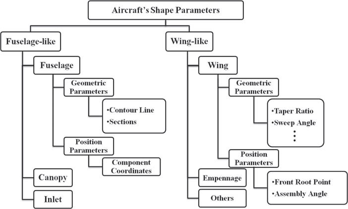
The design features of the aircraft’s whole shape include the shape features of the various components, and the assembly relationships among them. To describe the aircraft shape parameters based on the design features, the geometric and position parameters of the various components should be defined (Fig. 1). The geometric parameters are used to determine the shape of a single component. Moreover, the position parameters are used to determine the component’s assembly relationship with others. In addition, the components of an aircraft can be divided into fuselagelike and wing-like components. Fuselage-like components include the traditional fuselage, canopy and inlet; winglike components include the wing, empennage and others. Compared to the components’ geometry features summary method [11], design feature-based modeling can better describe the basic shape of the entire aircraft completely, and contribute to a faster forming of the aircraft shape scheme. However, different types of aircraft may have greatly different shapes, so that the method proposed in this paper applies only to jetfighters.
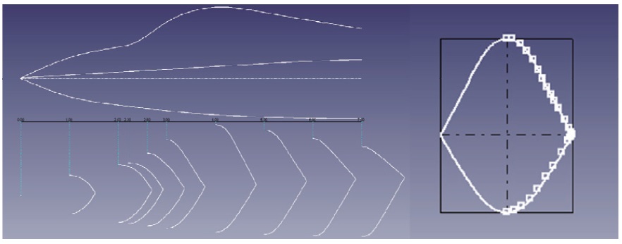
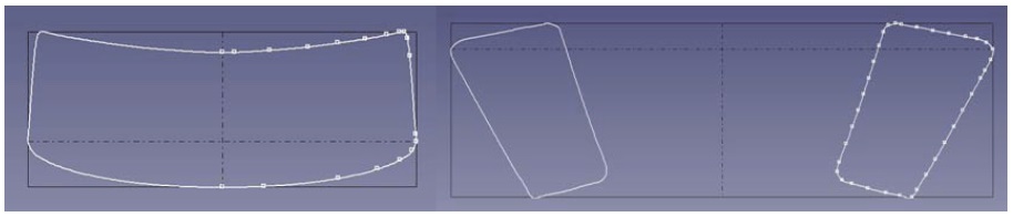
As shown from Fig. 1, the shape of the fuselage-like component is built with setting its contour line and sections (Fig. 2), and the shape of the wing-like component is built with setting its geometric parameters, such as taper ratio
and sweep angle. Its important to note that only the right side model is built based on the settings, and the use of the left side is generated by the mirror mode. To preserve continuity at the symmetry plane, the user is allowed to set the tangential vector in the section. Moreover, the positioning of the fuselagelike component is completed by setting the coordinates of the component’s origin, and the positioning of wing-like components is completed by setting the position coordinates, including the front root point and assembly angle.
The type of curves used in OpenCADS is the B-Spline curve. The B-Spline is defined as:
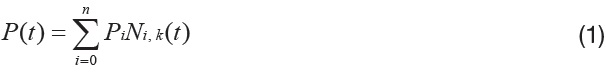
In the equation,
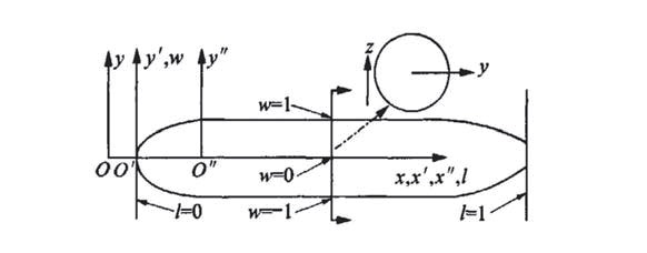
Firstly, inherited from OpenCADS, the coordinate system should be defined (Fig. 3). There are three sub-coordinate systems in this coordinate system, with different usage. The coordinate system Oxyz is regarded as the coordinate system of modeling, and the management reference point of the model’s actual geometry information. O'x'y'z' is the absolute coordinate system of the fuselage, and the head point of the fuselage is usually set as the origin of the coordinate system. O''x''y''z'' is the coordinate system of fuselage components
used for the modeling of components. The various fuselage components are completely assembled through the coordinate origin’s position of the absolute coordinate system of the fuselage [12]. In this paper, the origin of the fuselage component’s coordinate system is defined on the front surface of the fuselage component, and the origin of the wing component’s coordinate system is defined on the leading edge root point.
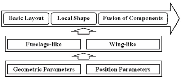
The process of design feature-based jetfighter shape modeling can be summed up in three stages, including basic layout modeling, local shape modeling, and fusion of components (Fig. 4). The accomplishing means is to respectively set the geometry and position parameters of the fuselage-like components and wing-like components.
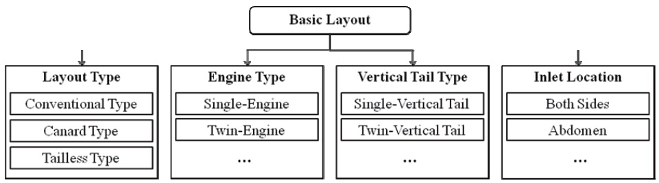
In this paper, the basic layout is defined as the four main elements, including layout type, engine type, vertical tail type, and inlet location (Fig. 5).
The layout type actually represents the relative relationship between the main wing and horizontal tail. Typical advanced jetfighters take the conventional type and canard type, and rarely take the tailless type.
Modern jetfighters are equipped with single or dual engines. The twin-engine jetfighter needs more fuselage space, so that larger sections should be set in fuselage modeling. Moreover, more space should be left for inlets.
Advanced fighters usually have single or dual vertical tails. The rough shape and location of vertical tails need be determined first in the stage of basic layout modeling, and can be adjusted in the stage of components fusion.
Inlet types of different jetfighters have many differences. Both sides and abdomen types of air intakes, or the modifications of these two forms, are common.
Jetfighter shapes are classified through the above four elements. Jetfighters with the identical four elements can be regarded as having the same basic layout.
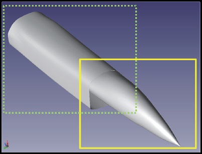
To completely achieve the basic layout, the rough shapes of five major components, including the forward fuselage, rear fuselage, main wing, vertical tail, and horizontal tail (canard), should be modeled and positioned. The fuselage is divided into two parts at the position near the inlet’s intake, for inlet modeling in the stage of local shape modeling (Fig. 6). The rectangle with solid line depicts the forward fuselage,
and the rectangle with dotted line depicts the rear fuselage.
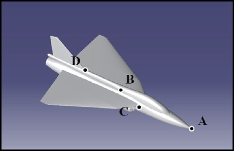
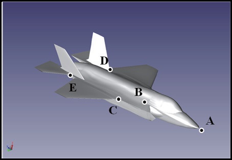
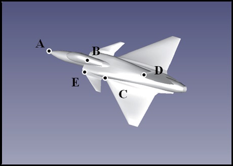
The achievement of the basic layouts are illustrated by the examples of F-35, JAS-39, and LCA, respectively, corresponding to the conventional type, canard type and tailless type (Figs. 7-9). Points A, B, C, D, and E in the figures represent coordinate system origins of the forward fuselage, rear fuselage, main wing, vertical tail, and horizontal tail (canard). After the shapes modeling, the basic layout of the jetfighter can be sketched, by setting the position parameters of these major components (Table 1).
The basic layout determines the basic shape of the aircraft (Fig. 10). The local shape modeling and fusion of components should be finished based on the basic layout, too. Moreover, the completed basic layout can be saved as a project, for shape modeling of the same or a similar aircraft design. Therefore, the stage of basic layout modeling is the core of the design feature-based jetfighter shape modeling method.
[Table 1.] The position of major components
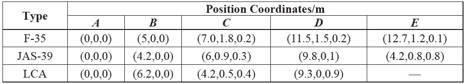
The position of major components
The stage of local shape modeling is to model the details of the jetfighter, usually including canopy, inlet and nozzle. Although not significant as the basic layout, local details are also important manifestations of the design features.
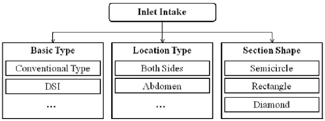
The following is an example of inlet intake, to illustrate the local shape modeling. In order to sort out the design features of the inlet intake, the elements, including basic type, location type and section shape, are defined (Fig. 11).
In this paper, the basic type refers to the conventional type and DSI (Diverterless Supersonic Inlet), which has become quite popular in recent years.
As previously described, the location type includes the
both sides type and abdomen type. The space where the inlet intake is located should be left to the stage of basic layout modeling.
The common section types of inlet intake can be divided into semicircular, rectangular, and diamond.
Summarizing the design features, the complex inlet intake is decomposed into simple geometric shapes that will be respectively modeled, by setting the contour lines and sections. It is worth noting that in the inlet intake modeling, the section shape embodies more design features (Fig. 12).
Through the first two stages, the basic shape of the entire jetfighter has been formed. Contemporary jetfighters often have a wing-fuselage fusion design with a smooth transition between the components, so a step is needed to modify the details of the junctions. The means of realization is regulating the details of the sections of the fuselage, to accommodate the other components. It is worth noting that the basic layouts of some jetfighters may be similar, but there are great differences between their fuselages and other components. Therefore, the sections of fuselage need a great adjustment, when the shape modeling is based on the existing projects of basic layouts.
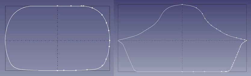
Figure 13 shows the sections of two mid-fuselages. The left one is traditional, and nearly circular. The right one embodies a stealth design with wing-fuselage fusion, and has a wide bottom, because of the equipped buried bomb
bay. Moreover, the figure obviously shows the deformation on both sides of the section, in order to better join the wing.
The fusion of components may not be decisive to the shape of the aircraft, but it is significant in improving the result of the modeling. In addition, a semi-automatic function is provided, to help the user to adjust the model. At this research stage, the semi-automatic function is achieved by fixing the contact section of the two connected fuselagelike components, and the contact airfoil profile of the two wing-like components.
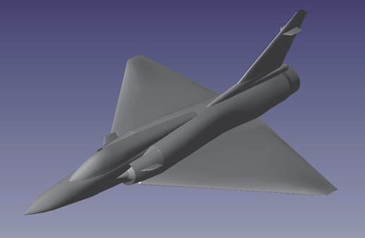
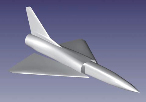
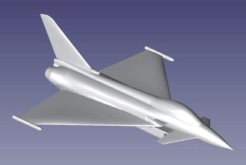
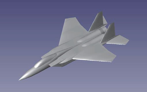
Figures 14-16 show more advanced finished jetfighter models that are completed by the design feature-based jetfighter shape modeling method. To cover the basic layouts of the form of the state-of-the-art fighter, the normal layout, no tail and canard layout, with distinct layout features of the wing-like components and inlets, are included [21,22]. From these sample cases, this method’s capability of jetfighter shape modeling can be verified.
The shape model of an aircraft is significant in the stage of conceptual design. Through improving OpenCADS, a method of design feature-based jetfighter shape modeling is researched. The general design features of a jetfighter are described. Through three stages, which are basic layout modeling, local shape modeling and fusion of components, the shape of a jetfighter can be achieved. Three sample cases of advanced jetfighters are listed, to verify the capability of the shape modeling method. The jetfighter shape modeling method based on design features can achieve a new design more quickly than the traditional parametric modeling, resulting in speeding the next process of analysis and optimization, to boost the general concept design.