Its aerospace system is the main indicator of the international power of any country concerned with guaranteeing security, the standard of scientific research and technical development. When designing the launch system of cargo and people into orbit, we used high-altitude aviation and rocket technology. In the future, almost all the projects are to design new space systems for multiple use - to launch loads into orbit and return from it. First, this is related to the use of winged spacecraft for descent and landing on usual aerodromes. To estimate the aerodynamic loads and to predict the landing area, one should know at the stage of initial design, the coefficients of aerodynamic forces and moments of spacecraft for varying temperatures, densities and flight velocities for numerous possible descent trajectories.
The development of spacecraft and rocket technologies requires reliable data on the aerodynamic and aerothermodynamic characteristics for hypersonic speed in an entire range of flow regimes, i.e., from the continuum flow regime to the free-molecular regime. During de-orbiting, the spacecraft passes through the free molecular, then through the transitional regime and the final flight is in the continuum flow.
It is well known that for flight in the upper atmosphere, where it is necessary to take into account the molecular structure of a gas, kinematics models are applied, in particular, the Boltzmann equation and corresponding numerical methods of simulation. In the extreme case of free-molecular flow, the integral of collisions in the Boltzmann equation becomes zero, and its general solution is a boundary function of distribution, which remains constant along the paths of particles [1]. While aircraft are moving in a low atmosphere, the problems are reduced to the problems that can be solved in the frame of continuum theory or, to be more precise, by application of the Navier-Stokes equations and Euler equations. It is natural to create engineering methods, justified by cumulative data of experimental, theoretical and numerical results, enabling the prediction of aerodynamics characteristics of complex bodies in the transitional regime [2].
The difficulty in the development of a hypersonic vehicle is caused by quite a number of problems of modeling fullscale flight conditions in wind tunnels. The analysis of the aerodynamics and aerothermodynamic characteristics of a hypersonic vehicle at high-altitude requires numerous numerical calculations [3-5].
To correctly simulate hypersonic flows, the flows must be understood and modeled correctly and this truer than in the numerical simulation of hypersonic flows. Hypersonics must be dominated by an increased understanding of fluid mechanics reality and an appreciation between reality and the modeling of that reality [6]. The benefits of numerical simulation for flight vehicle design are enormous: much improved aerodynamic shape definition and optimization, provision of accurate and reliable aerodynamic data and highly accurate determination of thermal and mechanical load [7]. Multi-parametric calculations can be performed only by using an approximation engineering approach. Computer modeling allows rapid analysis of the aerodynamic characteristics of hypersonic vehicles using theoretical and experimental research in aerodynamics of hypersonic flows.
The basic quantitative tool for the study of hypersonic rarefied flows is the direct simulation Monte Carlo method (DSMC) [8,2]. The DSMC method requires a large amount of computer memory and performance and is unreasonably expensive at the initial stage of spacecraft design and trajectory analysis. Approximate engineering methods pose a possible solution to this problem. These methods allow us to calculate aerodynamic characteristics of vehicles for multiple variants of free-stream parameters within a reasonable time and to refine the results at the most important segments of the flight trajectory by the DSMC method. The early work of [2] indicated that the local engineering method could have a significant effect on aerodynamic characteristics of various hypersonic vehicles.
The purpose of this work is to create an engineering program for aerodynamic characteristics calculation of the perspective hypersonic vehicles. This method is suited to calculate for hypersonic vehicles, taking into account the influence of Reynolds number, and provide good results for various vehicle shapes.
2. Calculation Methods for Hypersonic Aerodynamics
Difficulties of solving aerodynamic problems of overflow on bodies of rarefied gas stimulated the development of engineering semi-empirical methods based on the accumulated experimental data. The most suitable method to compute aerodynamic forces of a spacecraft relies on bridging formulae. When modeling the natural conditions, it is necessary to consider the basic similarity criteria. The hypersonic aerodynamic coefficients most commonly used parameters are:
Mach number M
Knudsen number Kn
Reynolds number Re
where, λ∞ - the mean free path,
The famous Newtonian sine squared law indicated that the force varies as the square of the sine of the deflection angle. More than half century later it was indicated that Newton’s sine-squared law was not very accurate and, indeed, the preponderance of fluid dynamic experience up to the present day confirms this finding, the exception to this is the modern world of hypersonic aerodynamics [9]. The pressure coefficient at all forward facing points of the body is
Cp = 2sin2 θ
where, θ is the local inclination of the surface to the free stream.
An alternative representation of the pressure coefficient for hypersonic flow, replacing the factor 2 by the appropriate value of the stagnation-point pressure coefficient at the flow condition of interest, which is known as modified Newtonian flow theory [10]
Cp = Cp,mod 2sin2 θ
where
Where,
For the last 50 years, the introduction of modified
Newtonian theory continues to be used often to generate approximation for the pressure acting on configurations in hypersonic flows [13-15].
In this work, the expressions for the elementary pressure forces and friction forces are applied in the form described in [2,16,17]. The local formulae take directly into account the geometry of the vehicle and calculate pressure and skin friction distribution on the body surface.
p = p0 sin2θ+ p1 sinθ
τ = τ0 sinθ cosθ
here,
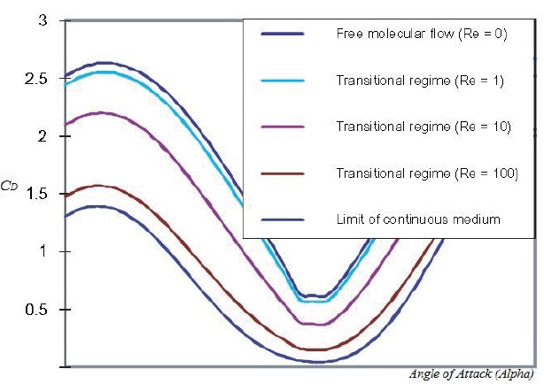
The dependency of the coefficients of the regime in the hypersonic case must ensure the transition to the freemolecular values at Re0→0, and the values corresponding to the Newton theory, methods of thin tangent wedges and cones at Re0→∞. By the analysis of computational and experimental data, the empirical formulas are proposed, as follow
p0 = p∞ + [p∞(2-αn)-p∞]p1/z,
p1 = z exp[-(0.125+0.078tw)Re0?фф],
Here,
Re0?фф = 10-m Re0, m = 1.8(1-h)3
Where,
The technique was proved to be good for the calculation of hypersonic flow for convex and not very thin bodies.
The calculation fully reflects a qualitative behavior of drag force coefficient
Thus, the locality method in the calculation of aerodynamic characteristics of the bodies in the hypersonic flow of rarefied gas in the transitional regime gives a good result for
3. Computational Results and Discussion
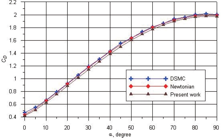
The coefficients of drag force
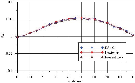
force acting on the vehicle and moment, respectively.
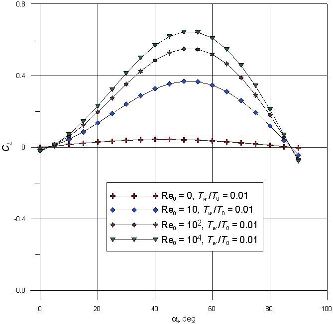
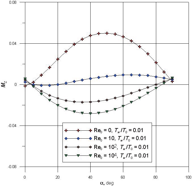
The calculation has been performed through the method described in the previous section within the range of angles of attack
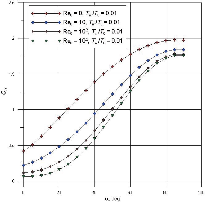
The dependencies of the drag force coefficient
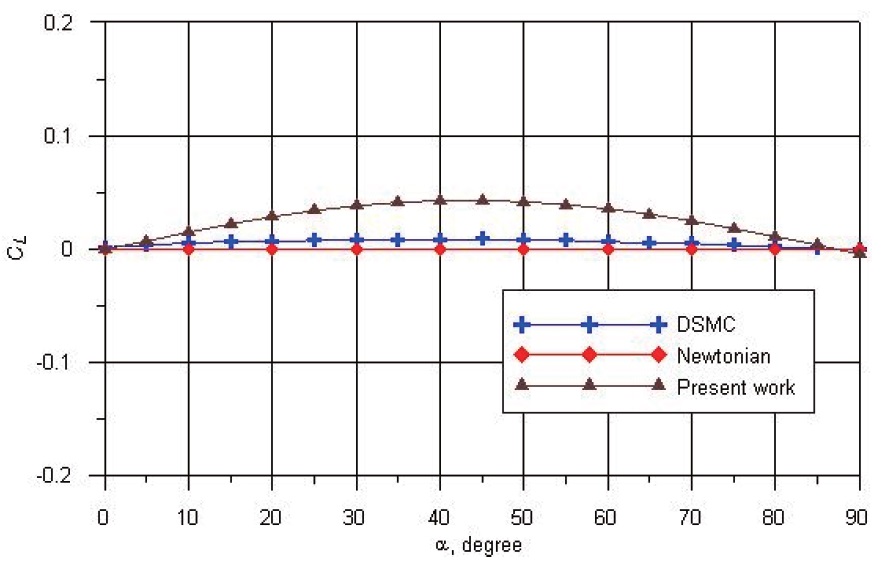
From these results, it can be seen that the influence of results by DSMC, Newton’s method and local engineering method at Re0→0 (in the free molecular regime) is not significant. The growth of a temperature ratio for the free molecular regime, leads to a considerable growth of the absolute value of
in respect to the coordinate origin, and these tendencies were noted to by analysis of the results obtained by the Monte Carlo method. Thus, it can see that the local engineering method gives good results in the calculation of aerodynamic characteristics of hypersonic vehicles in rarefied gas flow. The methods considered do not take into account the influence of the interaction of a boundary layer with the inviscid hypersonic flow at the large numbers of Re0.
It has to be pointed out that when the Reynolds number increased, the drag coefficients
Re0 ~ 102. At Re0 ~ 104, the value of
The analysis of different approaches to calculate aerodynamic characteristics of perspective spacecraft vehicles in rarefied gas flow were performed. The engineering method to calculate hypersonic aerodynamics in the transitional regime is described. The calculation results of aerodynamic characteristics for a spacecraft vehicle by the engineering method in transitional regime with various Reynolds numbers are presented. Comparison to Newton’s method and the DSMC method are described. We can reduce calculation errors in vehicle design projects by multiple calculations using this method. The above engineering method in transitional regimes gives a good result for a wide range of bodies. The obtained data can be applied in the future for hypersonic vehicle design.


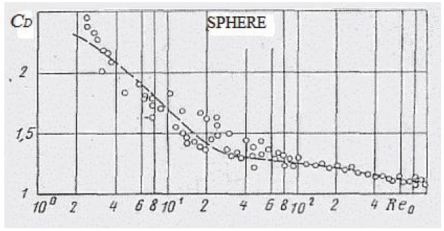
![Drag coefficient CD for a sphere at various Reynolds number [16]](http://oak.go.kr/repository/journal/12546/HGJHC0_2013_v14n3_215_f002.jpg)
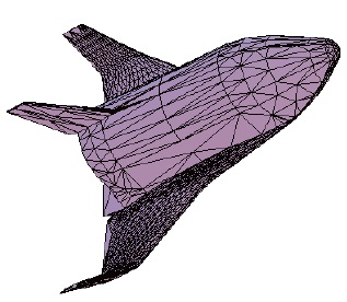
![Drag coefficient of Space Shuttle at the various stages of flight trajectories [2]](http://oak.go.kr/repository/journal/12546/HGJHC0_2013_v14n3_215_f003.jpg)