Recently, imaging system in automobiles can provide the assistance for parking as well as safety for the driver. Also to keep safety for drivers, many nation’s congresses are discussing laws including a requirement to mount a rear view camera on cars.
The camera for the automotive industry is divided into a sensing camera and a viewing camera according to the objective for use. The sensing camera is applied to detect an object behind a car in blind spot detection systems or night vision systems or lane departure warning systems and so on.
The object of the viewing camera is to see objects behind a car and in front of car. In this paper, a rear viewing camera is mainly discussed.
Normally the field of view of a rear viewing camera must be over 140 degrees at the horizontal field of view in order to see around a parking lot. The wider the field of view, the more elements are needed to correct field aberrations such as a lateral color, coma and astigmatism. In order to reduce the lens elements, plastic lens having an aspherical surface is frequently used for a wide angle lens.
Nowadays lens makers are developing a hybrid type which composites the plastic lens and glass lens together because the cost of a plastic lens is cheaper than a glass lens. In case of a fish eye lens, the fish eye definitely has a 180 degrees field of view at horizontal and consists of 6 elements or 8 elements. They produce a hemisphere image because of strong barrel distortion. Normally a distortion of fish eye lens might be over 150%. Therefore we must use an algorithm to correct a distortion.
In the other papers, they used an anamorphic surface to control the magnification with the field angle. They reported that an anamorphic lens can increase the resolution in the field of view of interest to meet the needs of specific applications. They defined the resolution as the angle coverage with each pixel. When comparing the anamorphic lens with a conventional fish eye lens, they found that an improvement factor up to 3.5 in resolution can be achieved according to an application. In case of indoor video surveillance, where the camera is always mounted on the ceiling, by controlling the slope of the distortion profile, they can get the periphery with high resolution. Where, high resolution by slope of distortion profile means unit pixel covers wider angle with respect to a resolution. Controlling a distortion is useful to design a wide angle lens. But an optical distortion is not improved but a distortion profile or image shape is changed. It is impossible to reduce an optical distortion by controlling the magnification.
Therefore, though an anamorphic surface is applied, image processing for the camera must be applied for reducing a distortion.1) Also, a cropping function in image signal processing might be needed to remove the unnecessary part of the overall image. Hence the cost of an image sensor is increased by additional functions.
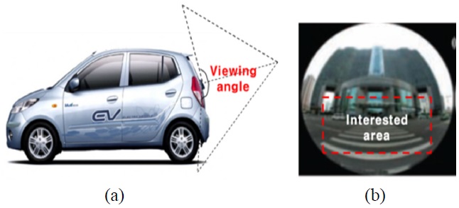
In this paper, to find a solution to reduce a barrel distortion, we invent a new design to image an area of interest. We show that the new off-axis optical system has a reflective surface and a refractive surface together. The left picture in Fig. 1 shows the position of the camera in the car and the camera’s view. And the right picture in Fig. 1 shows that the shape of the overall image from a wide angle lens is typically circular and an area of interest for drivers became a certain part of overall image. Our idea in the paper is to make a new optical system only imaging the area of interest on the sensor. That can be accomplished by introducing an off-axis optical system and free form surface. The mechanical shape of the new off-axis optical system can be optimized to match the camera mount on the car. As a result, eliminating an outer apparatus or bracket can reduce a total cost and strong barrel distortion is reduced by the free form surface.
In session 1 and 2, we introduce the design approach of an off-axis optical system for an automotive camera. Then we analyze the performance in comparison with a conventional lens in session 4. The tolerance and sensitivity for fabrication is represented in session 5. At last, the results of optical design are given and the conclusion is presented.
In order to select an view of interest from the overall view area, we introduce an off-axis optical system In contrast to conventional optical system which have a co-axis between lens and sensor. The new optical system consists of one glass lens and two prisms. The glass lens should be used for correction of spherical aberration and for reducing the aperture size of the other lenses. The prism has a combination of a reflecting surface and refracting surface. The reflective surface is the free form type, which can make the optics smaller, thinner and lighter compared with a conventional coaxial imaging system.
There are reasons why the reflective surface is used for a wide angle camera. It is effective to reduce the color aberration for a wide angle lens. Also a folded or de-centered optical system can be made thinner, but off-axis aberrations should be introduced at the reflective surfaces2). The following aberrations are introduced by the off- axis errors.
1) off-axis astigmatism
2) off-axis coma
3) off-axis distortions
4) off-axis tilting of the image plane.
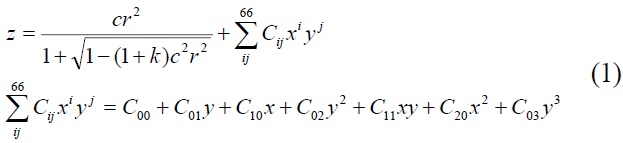
These aberrations, which do not occur in a coaxial optical system, also might be created at the center of the image plane. To reduce these off axis aberrations, it is effective to use a rotationally asymmetric curved surface (free form surface), represented by equation (1)
Z indicates the surface depth, Cij is the coefficient of the aspheric surface, K is the conic constant, C is the radius of curvature, r(x,y) is the distance from the optical center.3)
[TABLE 1.] The target specification
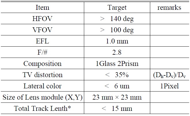
The target specification
Table 1 is the target specifications of an off-axis optical system. The total resolution of image sensor is 300 K (640 × 480), 1 pixel pitch is 6um. Total track length* means the total distance from the top of the lens module to the sensor. Where, Dh represents the distortion corresponding to horizontal angle, Dv represents the distortion corresponding to vertical angle.
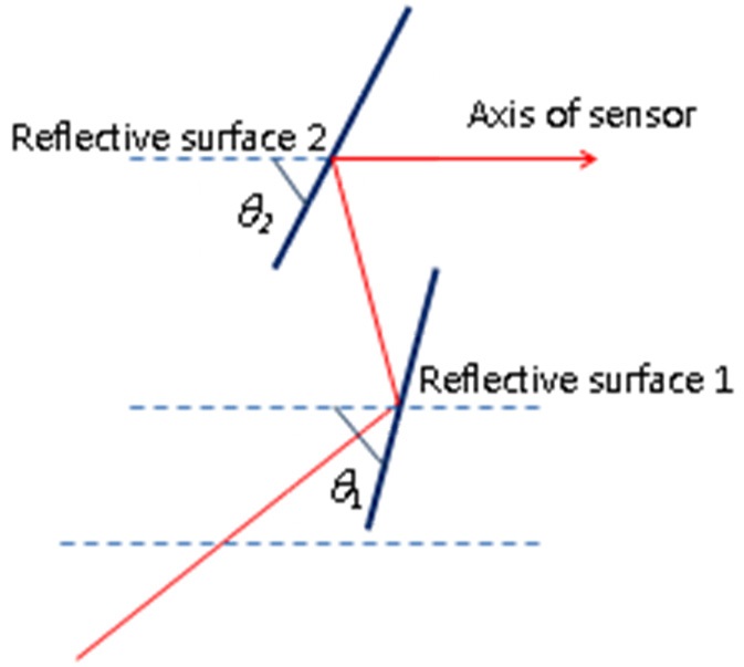
In this design, tilt angle for each component has a relation as a equation (2) below. All tilt angles are counterclockwise and the datum line for each angle is parallel to the axis of the sensor in Fig. 2, where, the dashed lines represent the datum line.
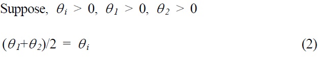
The mount angle on the car is the same as the tilt angle of the outer cover glass. A tilting angle of the cover glass has to be decided to see the bumper. If a target of vertical angle is over 100degree,
However, TIR only occur at reflection surface 1, because the full angle of reflection on reflective surface 2 is less than the critical angle. Therefore the reflective surface 2 should be coated with metal.
To design an optical system, we use a code-v® and Catia® which is famous for optical and mechanical design.
We’ll introduce the new optical system from the conventional wide angle lens through the following process. In
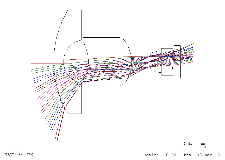
this paper, firstly, we analyzed the conventional optical system, and we set up a starting point which consists of three groups after allocating optical power for each element. The performance of the starting point should be suitable for VGA, Horizontal FOV is 135 degrees, the optical distortion is -67.68%. After finishing the optimization of initial design, we’ll compare the final design with on-axis wide angle.
Figure 3 shows the layout of the starting design consisting of three groups. Both sides of the 1st element have spherical surfaces. Both sides of the 2nd and 3rd elements in starting design have aspheric surfaces. And both elements are divided to two areas by a dummy surface. When we design the starting design, to find the optimum point quickly, the starting design is assumed to be an on-axis system or co-axial system. The dummy surfaces will be changed to reflective surfaces at the next step.
In the next step, the optical axis of the optical system is tilted with a specific angle. As we described in the previous section, each tilt angle is decided by equation (2).
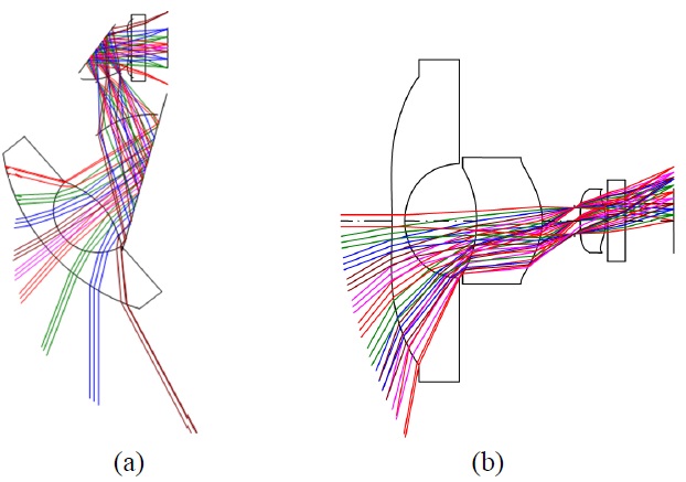
We compared on-axis wide angle lens with a group of three lenses and a new design. Fig. 4 shows the final design having the two reflective surfaces and the conventional lens for comparison of performance
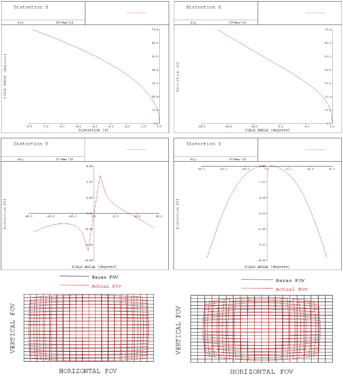
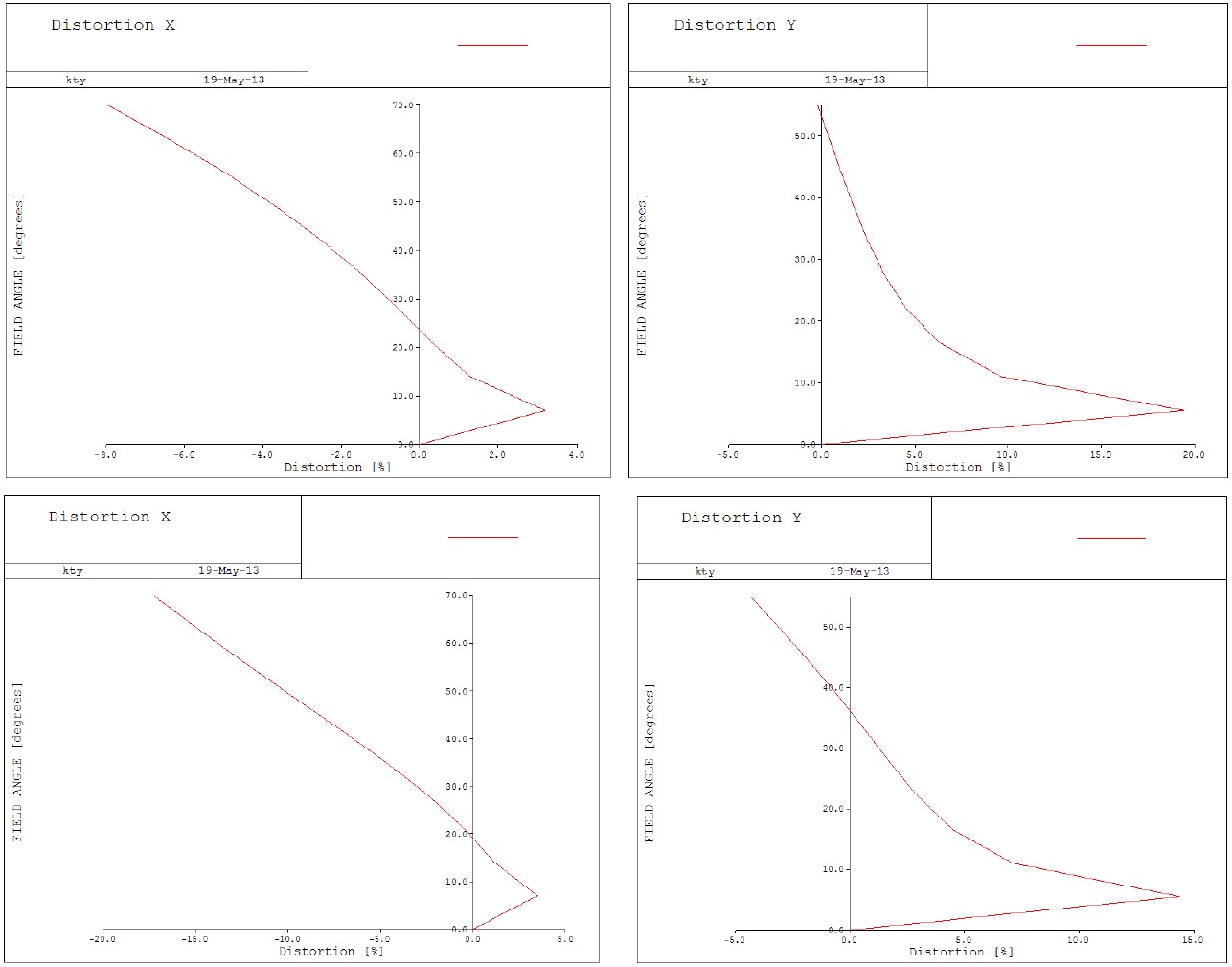
The types of surfaces of the conventional lenses are all aspheric. Field of view is the same as the off-axis lens. Fig. 5 shows the distortion at each direction and the grid distortion for comparison between the off-axis lens and the conventional lens. In order to analyze the distortion for the off-axis lens, we need to calculate distortion for each direction and we need a new approach to increase the accuracy for calculating a distortion. Classically, the distortion is measured as the difference between the paraxial chief ray height and the real chief ray height over the field. This method is appropriate for rotationally symmetric systems, but can be
an inaccurate method of measuring distortion for off-axis systems or systems with lenses with a high level of anamorphism. Therefore, in this paper, we introduce the modification for calculating the distortion which helps measure the distortion in systems that are off-axis and the paraxial chief rays might not be appropriate. The alteration involves setting up the “paraxial” distortion grid using a real ray traced at 5% of the maximum field. The “paraxial” distortion grid is then set as a grid with equal spacing between each point, based on the spacing between the chief ray at 0 field and the chief ray at the 5% field.
In this paper, the distortion is then measured as the difference between this “paraxial” grid, and the real chief ray height at various field intervals. In other words, we
[TABLE 2.] Real ray position at image plan in off-axis lens
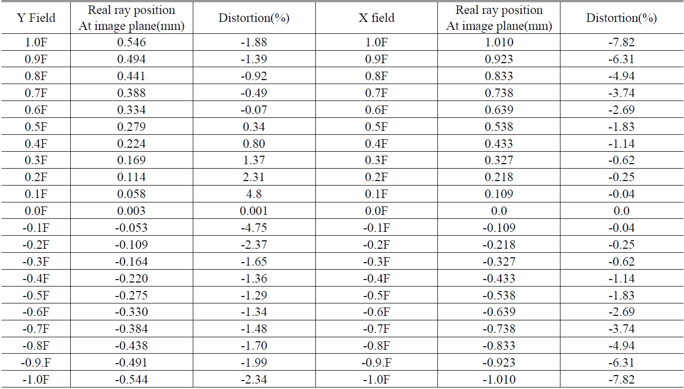
Real ray position at image plan in off-axis lens
determined the scaling factor by sampling the central 5% of the full field for each direction.
Distortion X and distortion Y in Fig. 5 mean the distortion for each direction calculated with scale factor. The x, y direction’s scale size in this grid distortion plot is 0.109 mm, 0.056 mm respectively.
The maximum distortion of conventional lens has the -17.5% at x-axis, -6% at y-axis. But the maximum distortion of the off-axis lens has the -7.82% at x-axis, 4.8% at y-axis. For the case of the off-axis lens, the distortion for the x-axis is symmetric but the distortion for the y-axis is asymmetric. The reason why the distortion is asymmetric is that real ray position at positive field angle does not coincide with the opposite side. Sampling scale in the grid distortion plot is 0.056 mm and real ray position at the image plane is 0.058 mm corresponding to 0.1 field, real ray position at the opposite side is -0.053 mm following Table 2. The alteration of distortion sign comes from the difference of real ray positions at the image plane. However, we can’t perceive the sign change over the central part of the y-direction because this difference is too small compared this sampling scale.
As a result, the off-axis lenses have the lower distortion than conventional lenses. Anamorphic ratio of the off-axis lens is about 0.97.
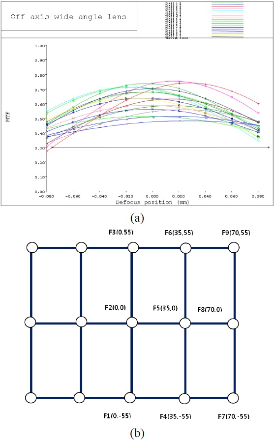
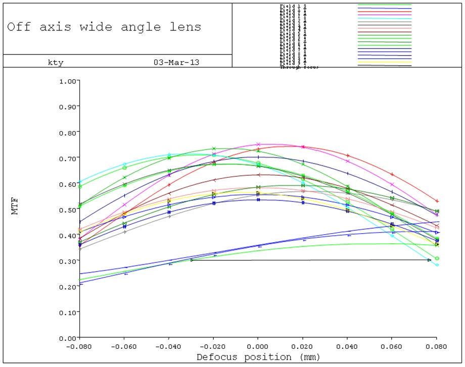
Left plot in Fig. 6 shows the through focus MTF of off-axis lens at 40l p/mm(Sensor nyquist frequency*0.5). Lens performance can be suitable for VGA.
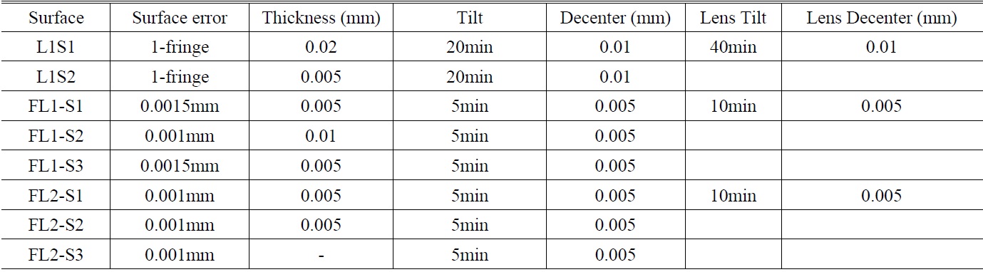
Tolerance table
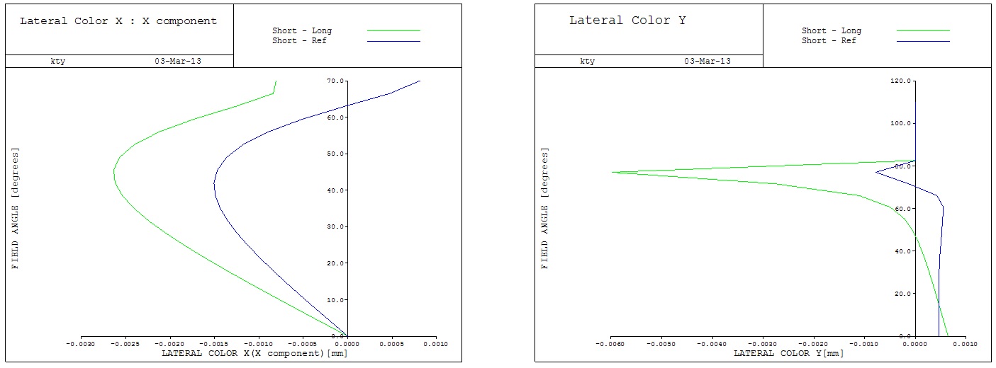
Figure 7 shows that the lateral color for each direction is less than 6 um.
To compensate a tilting error and alignment between the prisms and cover glass, self- alignment is applied between the cover glass and the first prism. And the alignment error between first prism and second prism is reduced by guide boss. To reduce an aperture size, aperture shape for cover glass and prism is made to a rectangular shape.
A tilt error of the each refractive surface at prism lens (FL1, FL2) is limited within 5min. The thickness and sag error of prism lens are permitted to 0.005 mm and 0.001 mm respectively. Other tolerances are listed in Table 3. Then, to find a best position, an axis aligner is adopted for the assembly process. Using the equipment, it is possible to measure the MTF relative to each direction. Finding the best position depends on MTF data. Hence, the compensator is set to distance from the image plane.
After considering the tolerance, MTF is decreasing in some degree but the overall performance is good for
criterion of VGA. Fig. 8 shows the through focus MTF result at 40l p/mm
Surface errors of the reflective surface affect image quality. In particular, the symmetry of image becomes to be deteriorated. In order words, the focus difference between
upper field and lower field is larger as compared Fig. 6 with Fig. 8. Additionally these errors influence the off-axis aberration. We investigated how the distortion is changed by tolerances listed in Table 2. Fig. 9 represents the distortion in the off-axis system and the distortion in the conventional optical system after considering tolerances. The off-axis distortion occurs in both systems. In order to compare, all allocated tolerances are similar for both systems.
The reason why the distortion at the center area gets worse is that the reference points do not match to the image center after tolerances are allocated in the optical system. That is the position of reference ray at center field is dramatically changed in both systems. After all, when we consider all tolerances listed in Table 2, the delta distortion of off-axis lens for each direction is 11.18% at x-direction, 19.63% at y-direction. Where, distortion is defined as Dmax-Dmin.(Dmax corresponds to the maximum value of distortion at overall field, Dmin corresponds to minimum value at overall field)
The delta distortion of the conventional lens for each direction is also 20.7% for the x-direction, 18.7% for the y-direction. Here, we can know the sensitivity of y-distortion in both lenses is bigger than for the x-direction. Also contrary to our expectation, the distortion of the off-axis lenses is not bigger than the distortion of the conventional lens. However we have to find a way to compensate the sensitivity of the y-direction in the future.
In this paper, we studied the new concept design for a wide angle camera. Since the area of interest is only imaged on sensor or image plane, we accomplish the lower distortion using the optical method. Off axis wide angle lens has not only the lower distortion but the image quality is not bad compared to the conventional lens. The asymmetric field results in smaller field; therefore the aberration at the corner field is less than an aberration of the symmetric optical system.
Also, there is no mechanical apparatus needed to mount the camera. The tilt angle of the camera is decided by the
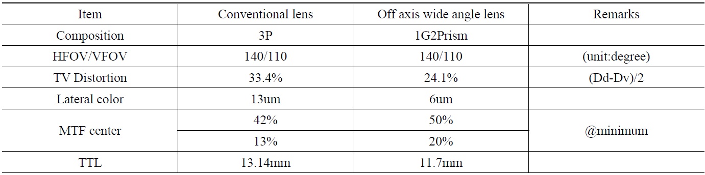
Design result
tilting angle of the first lens. Therefore we can reduce the cost.
But in previous section, we considered the tolerance, and analyzed the performance. As the result, tilt error between the first lens and second lens has most sensitivity. Errors of the reflective surfaces affect the focus difference. Therefore we need alternatives to prevent the shrinkage in the injection process.
Finally, the results of design almost meet requirement. In comparison with the conventional camera, off -axis optical systems have better performance and lower height than coaxial imaging systems as listed in Table 4.
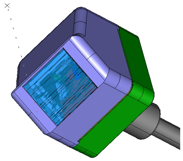
In the future, we will have a plan to make a prototype camera module. Fig. 10 represents the expected mechanical shape of the camera module.