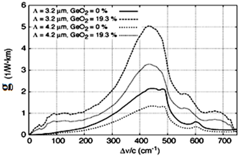
Nowadays a Raman amplifier is considered as a key component in realizing the wide-band amplification due to the low-noise operation and optical amplification in any wavelengths [1]. Over the past few years, photonic crystal waveguides have been widely studied, modeled and fabricated due to their peculiar properties such as endlessly single-moded [2], high-nonlinearity [3,4], overall controllable dispersion properties [5,6], bandwidth improvement [7,8] and enhanced coupling properties [9]. A new fiber called the holey fiber is a category of photonic crystal fibers (PCFs) and has been used in Raman amplifiers as the gain medium [10,11]. Such fibers consist of a pure silica core surrounded by a regular array of longitudinal air holes and can offer tight modal confinement. Thus they can provide an effective nonlinearity per unit length and can have the same order or higher than a conventional fiber. Their Raman efficiency defined as the Raman gain coefficient can be divided by the pump effective area and is expected to be much higher than that of a standard single-mode fiber (SMF). In [12], authors report the experimental study of the effect of a nonlinear PCF on the noise characteristics of a distributed Raman amplifier. There are two types of reported optimization work about the PCF RAs. In the first type, Raman gain is inherently flat or may possibly have optical amplification just by using one laser pump [13]; whereas in the second type, because of the gain non-uniformity, gain flatness can achieve by application of many pumps [14]. In triangular PCFs, gain can be increased by varying the geometrical parameters in the fiber cross section such as hole distances, pitch wavelength and their ratio and higher GeO2 percentages [15]. The present study aimed to propose a more powerful algorithm called fuzzy adaptive modified particle swarm optimization (FAMPSO) to choose pump power and pump wavelength for a
Taking into account the loss, noise and Raman interaction, the optical power evaluation along the waveguide (z-direction) is determined by [15]:
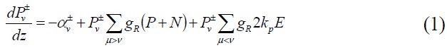
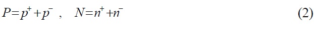
Where
PSO is an optimization algorithm inspired by a habitation such as birds. This method is based on two points: artificial live and evolution. In the extension of PSO algorithm, the possible solutions of the desired optimization problem are regarded as non-bulky birds and any element of this colony called a particle. They can fly in an n-dimensional space and correct their trajectory based on the previous experiments as well as the neighboring particles. For particle number i, the displacement vector Xi is defined as:

Where

The best former position Pi in the search space of

Using these definitions, we can find the new positions by the aid of some weighting and learning factors which affect the algorithm searching procedure severely [16].


Where
One of the disadvantages of the original PSO is falling in a local optimum point, so in order to improve the convergence property and accuracy of the PSO algorithm, this paper presented a modified particle swarm optimization method. Premature convergence can take place under different situations such as the population has converged to local optima, the population has lost its diversity, and the search algorithm has proceeded slowly or hasn’t proceeded at all. Mutation is a powerful strategy to increase the population diversity and improve the PSOs performance [18]. This paper employed a new mutation operator described as follows: In each iteration, three vectors are selected randomly (

Where
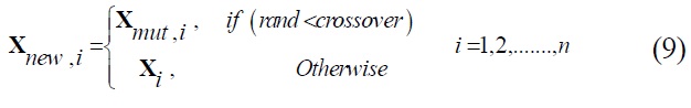
Usual crossover is selected in the range of: 0.1 < crossover < 0.9. In this paper
2.3. Adjusting the Learning Coefficients
Learning coefficients,
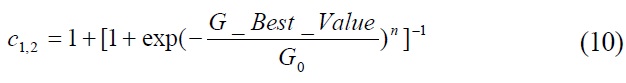
We chose n = 2 and
2.4. Fuzzy Formulation for Tuning of w
Weight coefficient determines the effect of the past velocity experience on the present one. The right choice of this parameter results in the balance between global and local search of PSO algorithm. Great weight coefficient enhances the global search performance and small weight coefficient improves the local search. The parameter
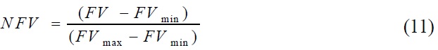
In Eq. (11) FV is a current best performance evaluation and the calculated value of FV from Eq. 11 at the first iteration may be used as

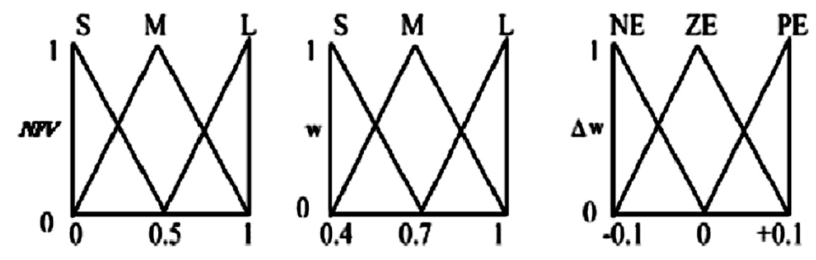
For achieving the optimal point, objective functions should be described by membership functions. In this paper, for simplicity, all the membership functions are modeled with triangular shape and also they can take one of the three following status: Small (S), Medium (M) and Large (L). In Table 1, output variables of fuzzy sets are presented in three forms of linguistic values; NE (Negative), ZE (Zero), and PE (Positive) with related membership functions, as shown in Fig. 2. Rules of fuzzy sets are shown in Table 1. There are nine possible rules for two input variables and three linguistic values for all input variables. Each fuzzy rule as from an “IF-THEN” statement like the following rule, for example: If
Based on the above theoretical description, we simulated our optimization method by using FAMPSO as shown in the flowchart of Fig. 3.
[TABLE 1.] Fuzzy rules of the input and output variables
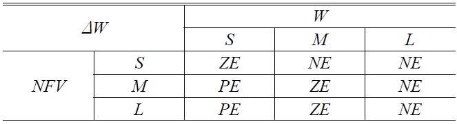
Fuzzy rules of the input and output variables
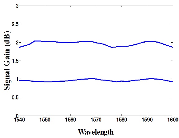
Consider a WDM system with 16 -channels. There is a grid of 3.75 nm with signal powers of about 20 mW. In this simulation we assumed that the lossy fiber has a length of about 10 Km. Runge-Kutta and a shooting method is used to solve the pump and signal interaction equations [21]. Our goal is to minimize the gain ripple in the C-L band by utilizing of the FAMPSO method to introduce optimizing sixteen parameters; the wavelengths and power levels for the 8 pumps range are from 1420 nm - 1520 nm and 0 mW - 120 mW respectively. For Optimizing gain ripple, the FAMPSO method should be minimizing the following function:
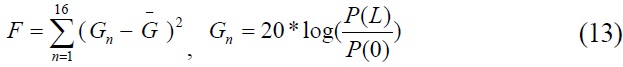
In this equation
[TABLE 2.] Optimization results for eight-pumps of PCFRA
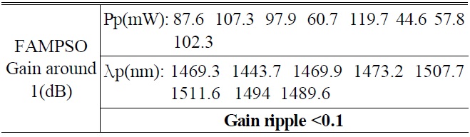
Optimization results for eight-pumps of PCFRA
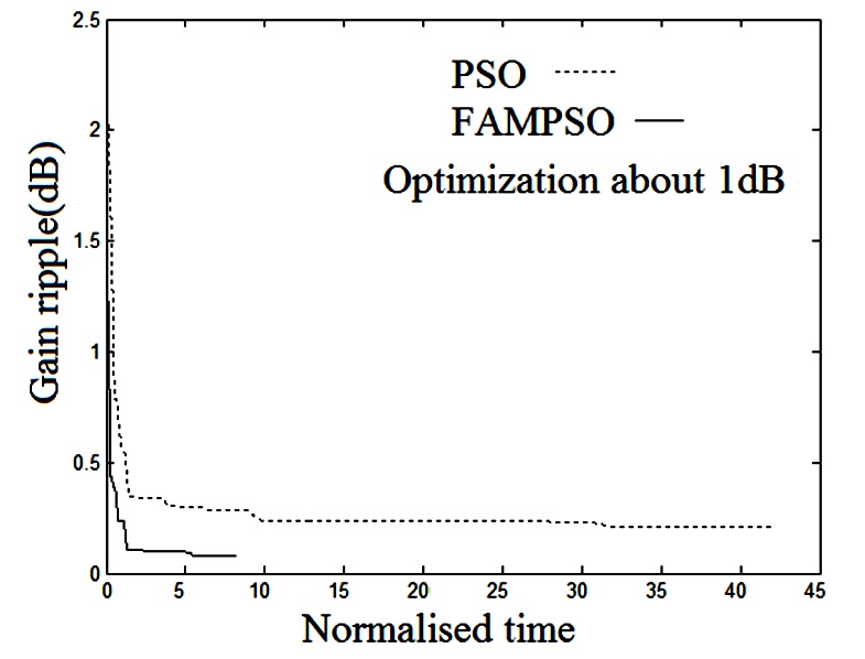
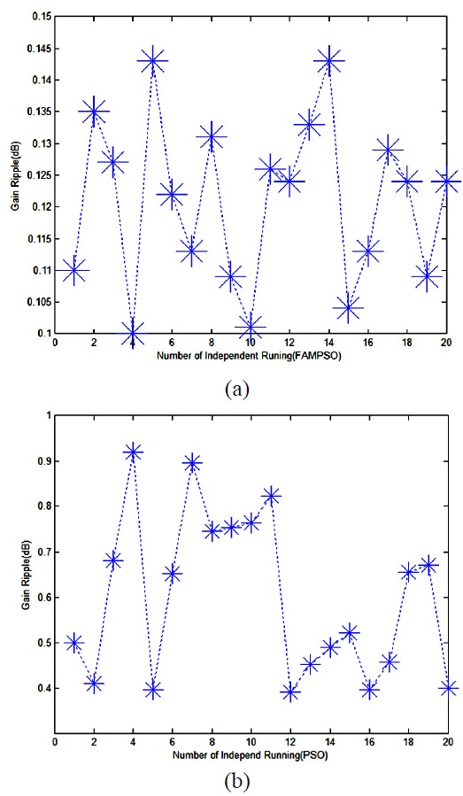
uniform On-Off Raman gain with eight pumps for which the maximum powers is less than 120 mW. Fig. 5 shows the gain ripples versus the number of iterations for the standard PSO and the proposed FAMPSO method. Indeed, the time consumption of the proposed method comparing with the classical PSO is shown in this figure. As shown in this figure, FAMPSO algorithm is performing better than PSO in terms of convergence speed and accuracy. Finally, Fig. 6
shows the development of the minimum gain ripples for 20 independent algorithms running which are obtained by PSO and FAMPSO algorithms. As it is seen, the FAMPSO method is more reliable than the classical PSO.
We simulated the optimum solution for a system of RA with eight backward pumps, for photonic crystal fiber we used a new optimization algorithm named FAMPSO. Designing a PCF-RA with a flattened gain done in the C and L band and the pump powers and the pump wavelengths were calculated so that a gain ripple of about 0.1dB reached. This method not only enhances the accuracy of design Raman amplifier parameters but also increases the reliability and speed of design parameters.