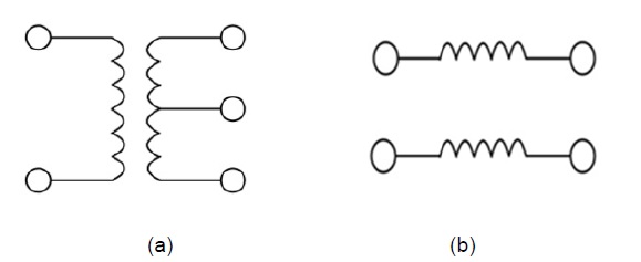
Baluns composed of one unbalanced port and two balanced ports have been used in numerous circuits, including pushpull amplifiers, balanced mixers, and balanced antennas [1-4]. The purpose of a balun is to form a transition from an unbalanced port to two balanced ports or from two balanced ports to one unbalanced port, and they can be used as impedance transformers with an arbitrary transfer ratio. Baluns are classified in various ways depending on the operating frequency range, the operating power, the frequency bandwidth, and the principle of operation of the component [5,6]. Radio frequency (RF) baluns for frequencies above the ultra-high frequency band can be divided into flux-coupled balun transformers and transmission-line balun trans-formers. The flux-coupled balun transformer must have direct current (DC) isolation from the primary to secondary coils, as shown in Fig. 1(a). The flux-coupled balun transformer can provide a wide range of impedance ratios. But, the transmission line balun transformer is impossible to achieve DC isolation between the primary and secondary coils, as shown in Fig. 1(b). The trans-mission line balun transformer can operate at higher frequencies and over a greater bandwidth than the fluxcoupled balun transformer.
A balun with a Wilkinson power-divider is a type of transmission-line balun transformer. In particular, a balun having the structure of a Wilkinson power-divider is a widely used high frequency component because the input and output impedances are 50 Ω. Wilkinson-type baluns generally consist of a Wilkinson power-divider and additional circuits to create a phase difference of 180° between the two balanced ports [7-10].
This paper proposes a novel Wilkinson-type balun without any additional circuits for the phase difference of 180°. The suggested balun has good balance cha-racteristics, including the reflection value at the two balanced ports and the isolation value between them. Assessment of the operational characteristics of the fabricated balun shows values similar to simulated values using the advanced design system (ADS) simulation pro-gram. The operating principles and characteristics of the suggested balun are described below.
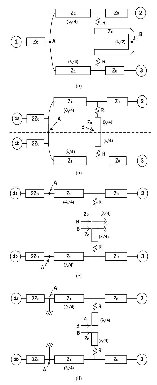
The block diagram of the suggested balun is shown in Fig. 2(a). This Wilkinson-type balun has a similar structure to that of a Wilkinson divider, except for two differences. First, one of the two power dividing lines is a -λ/4 transmission line. Second, it inserts a λ/2 transmission line between the two output ports. Even/odd mode analysis was used to calculate the circuit impedance of the su-ggested balun and to explain its operating principle. The block diagram of the suggested balun can be modified to give the equivalent circuit, as shown in Fig. 2(b). Using Fig. 2(b), we can treat the two (even and odd) modes separately. Fig. 2(c) is the equivalent circuit for the even-mode analysis, and Fig. 2(d) is the equivalent circuit for the odd-mode analysis. In the first case, point “A” is short and point “B” is open, as one signal path of the two balanced ports occurs with a phase shift of +90° and the other signal path occurs with a phase shift of -90° in the odd-mode analysis. We know that the short point changes to open (or

that of Zo, and the length should be such that it gives a λ/4 or -λ/4 line in order to achieve a low reflection value. If Zo is 50 Ω, R and Z1 must be 50 Ω and 70.7 Ω, respectively.
III. FABRICATION AND MEASUREMENT
The λ/4 transmission line of the suggested balun can be made easily using a microstrip line. However, making the -λ/4 transmission line is not easy. Replacing the -λ/4 transmission line with a 3λ/4 transmission line is not a viable option, as a 3λ/4 transmission line would result in an unacceptable delay time between the two balanced ports in the balun. Our solution is to make the -λ/4 transmission line using a composite right/left-handed (CRLH) transmission line [11-15]. Microstrip, strip-line and coplanar waveguide lines are homogenous trans-mission media. These transmission lines can be modeled with equivalent circuits consisting of distributed capa-citance and inductance elements. A cell consisting of a series inductance and a parallel capacitance is generally referred to as a right-handed transmission line (RH-TL); the phase velocity and the group velocity in RH-TL cells are positive. A cell consisting of a series capacitance and a parallel inductance is called a lefthanded transmission line (LH-TL); the LH-TL has a negative phase velocity and a positive group velocity. This LH-TL does not exist in practice; however, a virtual transmission line consisting of lumped elements can model the LH-TL behavior. In the suggested balun, it fabricated a virtual LH-TL using capacitors and inductors. The structure has an equivalent circuit containing both the RH-TL equivalent circuit and the LH-TL equivalent circuit, and is known as a CRLH-TL. In a CRLH-TL, the transmission line may have RH-TL or LH-TL behavior depending on the operating frequency.
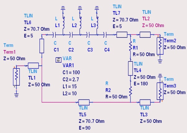
Fig. 3 shows a CAD schematic of the suggested balun. The lower of the two lines for power distribution is the λ/4 transmission line with the a line width equivalent to a characteristic impedance of 70.7 Ω. However, the upper line is a LH-TL consisting of series capacitance and parallel inductance that acts as the -λ/4 transmission line (equivalent to -90° phase change). As a result, the input signals of the balun separate two balanced signals of the same magnitude, and the 180° phase change occurs via the two 70.7-Ω dividing lines. Two 50-Ω resistors and a λ/2 transmission line are inserted between the two balanced ports to match to the balanced port and preserve isolation between the two balanced ports, as shown in Fig. 3.
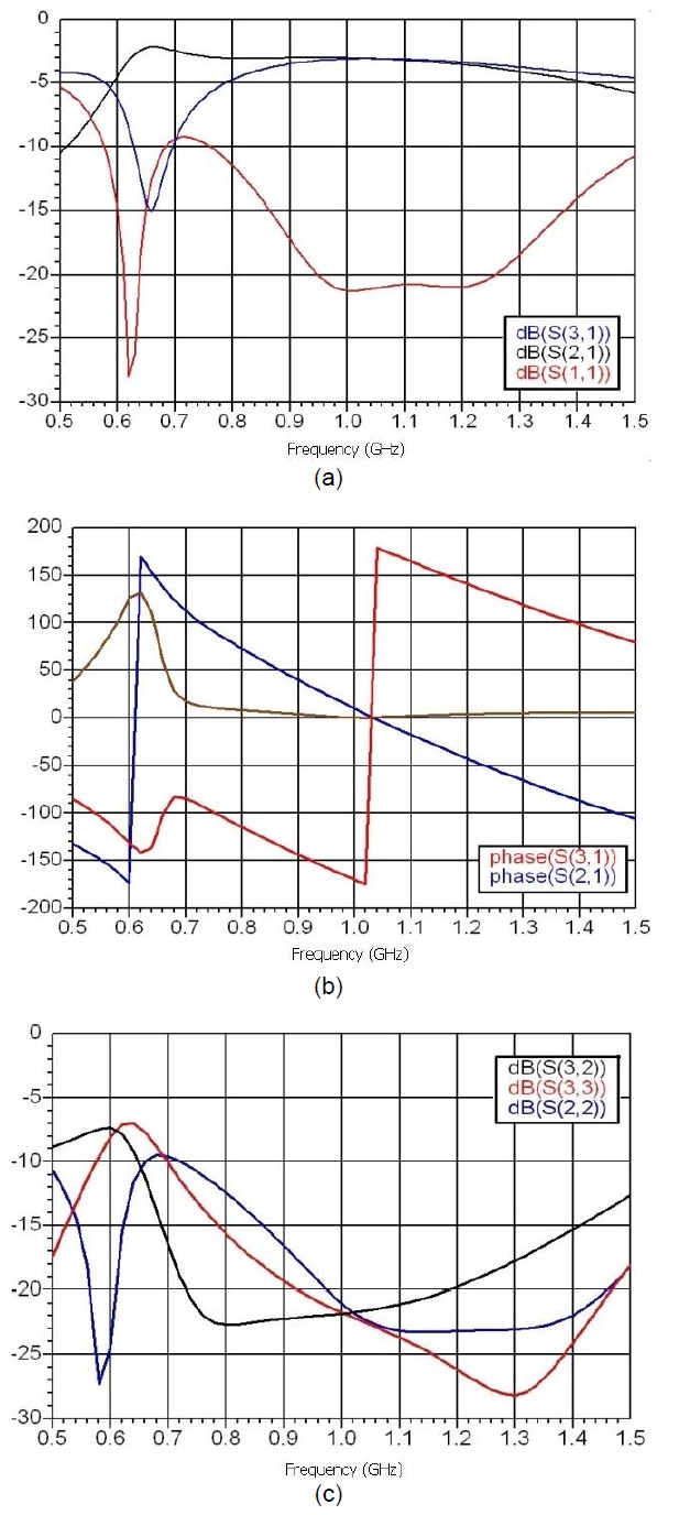
Fig. 4 shows the lumped element model of the balun and Fig. 5 shows simulated results using the ADS simulation program. Port 1 is the unbalanced port; port 2 is one of a pair of balanced output ports and is the CRLH transmission line; port 3 is the other balanced output port and is the λ/4 transmission line. It used ideal two-terminal transmission lines, and the values of the lumped element components for the CRLH transmission line were C1 = C4 = 100 pF, C2 = C3 = 2.7 pF, L1 = L3 = 15 nH and L2 = 10 nH. The simulation results are as follows. The reflection coefficient (S11) of the input port was less than -20 dB in the range 0.96?1.26 GHz, and the trans-mission coefficients (S21 and S31) were within ± 0.1 dB of the magnitude of the difference between the two inputs and 180° ± 5° of the phase difference in the range 0.93?1.13 GHz. The reflection characteristics (S22) of port 2 were less than -20 dB in the range 0.97?1.46 GHz and the reflection characteristics (S33) of port 3 were less than -20 dB in the range 0.92?1.47 GHz. The output isolation characteristics (S32 and S23) between ports 2 and 3 were less than -20 dB in the range 0.74?1.22 GHz. The design center frequency of the balun was 1 GHz, and the simulated results show it operating at a center frequency of 1.04 GHz, since the capacitance and the inductance used were values of commonly existing lumped elements. At the operating frequency of 1.00 GHz, the simulated operating characteristics were as follows: S11 = -21.3 dB, S21 = -3.10 dB, and S31 = -3.06 dB, S22 = -21.2 dB, S33 = -21.9 dB, and S32 = -21.9 dB, with a phase difference of 179.8° between the two balanced ports.
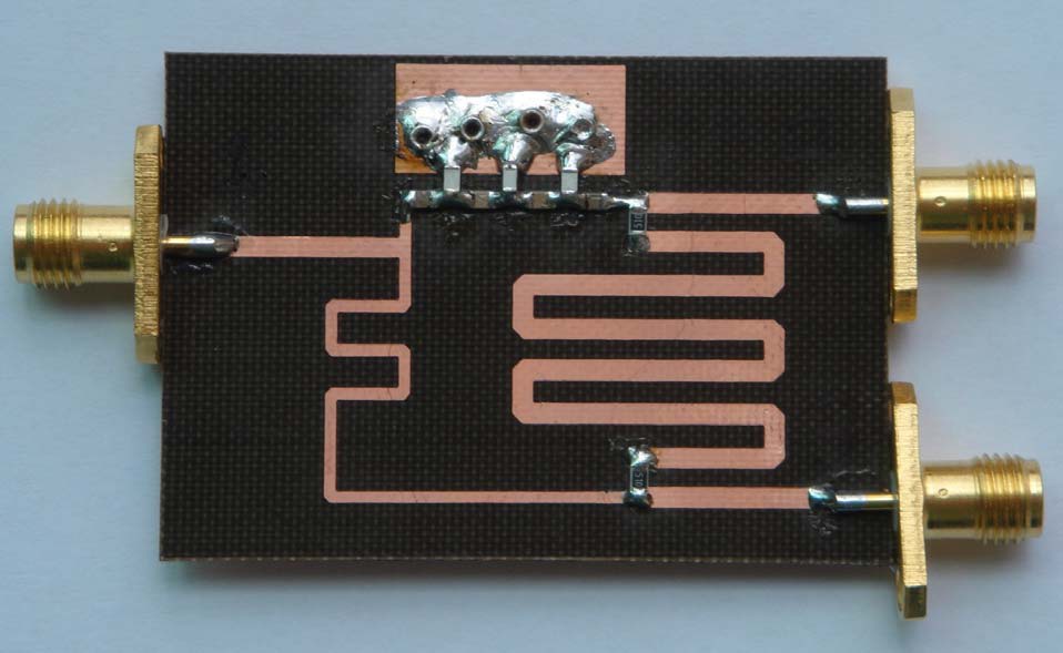
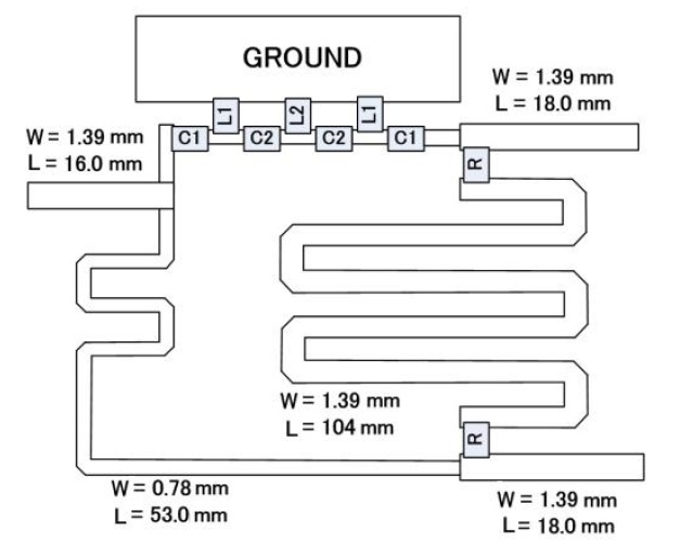
Fig. 6 shows a photograph of the fabricated balun on TLX-9 (εr = 2.5) 20-mil substrate at 1 GHz. Z1 and R have values of 70.7 Ω and 50 Ω, respectively, giving an input and output impedance of 50 Ω. The microstrip line width is 1.39 mm, and the 50 Ω λ/2 line length is 104 mm as CAD schematic. The 70.7 Ω λ/4 line length is 53 mm, and the width is 0.78 mm.
The capacitors and inductors composing the CRLH transmission line for the -λ/4 electrical line length were as follows, C1 = 100 pF, C2 = 2.7 pF, L1 = 15 nH, and L2 = 10 nH, as ADS simulation values.
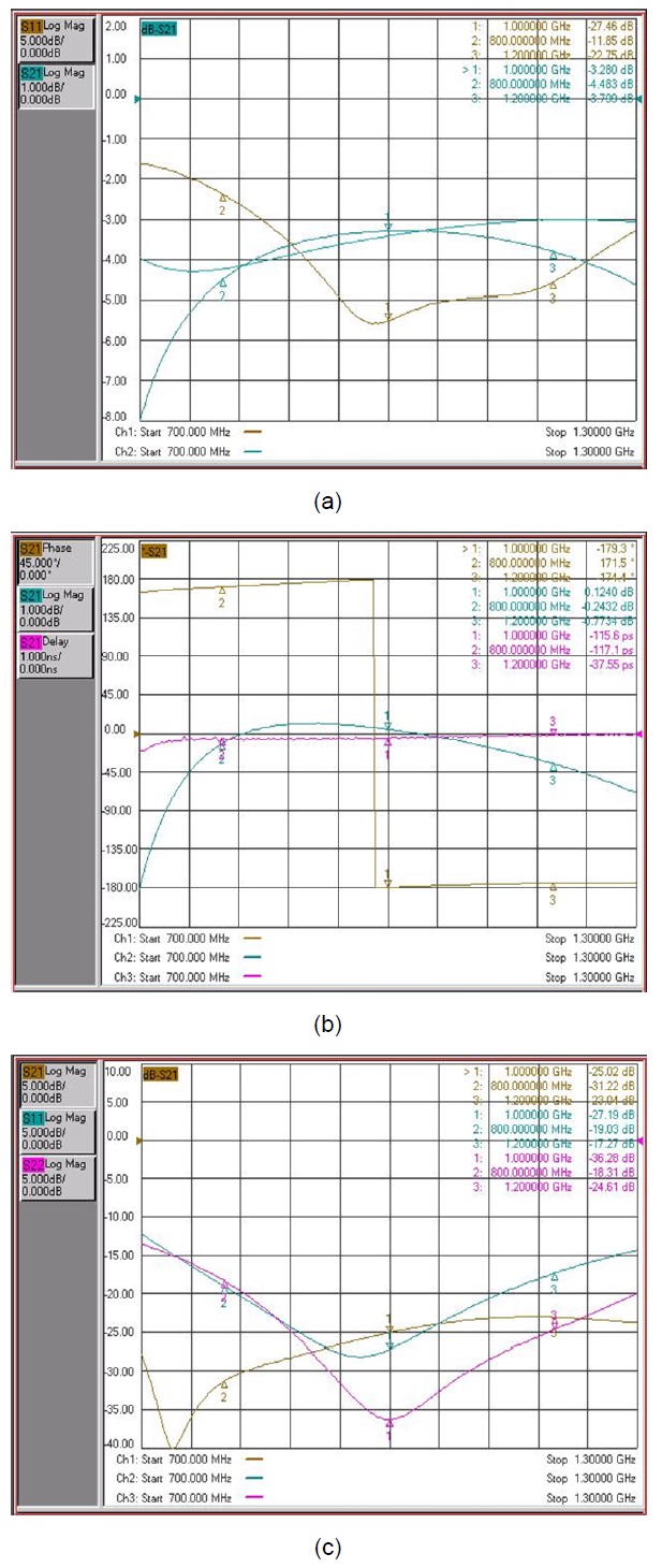
The operating characteristics of the fabricated balun are shown in Fig. 7, (line no. 1, unbalanced port; 2, CRLH transmission line port; 3, general microstrip line port). Measurements on the fabricated balun were performed using a N5230A network analyzer (Agilent Technology, Santa Clara, CA, USA). The fabricated balun has values of, S11 = - 27.46 dB, S21 = -3.40 dB, and S31 = -3.28 dB, a phase difference of -179.5°, a magnitude difference of 0.12 dB, and a delay difference of 0.1 ns, with S22 = -36.28 dB, S33 = - 27.19 dB, and S32 = -25.2 dB at 1 GHz. The delay difference of 0.1 ns gives rise to a time difference within one cycle (as one cycle at 1 GHz takes 1 ns). The characteristics of the fabricated balun exhibited very good agreement compared with the simulated data for the port matching characteristics (S11, S22 and S33) and the isolation characteristics between the two balanced ports (S23 and S32). However, the power transmission characteristics (S21 and S31) of the fabricated balun were worse than those of the simulated structure. Nevertheless, the differences between the simulated and measured operating characteristics were not significant. The si-mulated results using ADS were very similar to the measured data, and this shows that the Wilkinson type balun can be modeled effectively using the ADS simulation program. From the measured results, the novel balun is confirmed to have good operating characteristics, including the reflection value at each port and the isolation value between the two balanced ports.
A Wilkinson-type balun having a good reflection value and a good isolation value was suggested and fabricated. The λ/4 transmission line of the suggested balun was
realized using a microstrip line, and the -λ/4 transmission line was realized by a combination of series capacitors and parallel inductors creating the CRLH trans-mission line. The balun had a 50 Ω λ/2 transmission line between the two balanced ports, giving good reflection and isolation values. Fabricated at 1 GHz, the balun gave the same delay time from the unbalanced port as from the two balanced ports. The device showed an insertion loss of 0.4 dB, a magnitude difference of 0.12 dB, and a phase difference of -179.5°, with good reflection and isolation values. And, the suggested balun was si-mulated by using a ADS simulation program. The simulated results using ADS were very similar to the measured data, and this shows that the Wilkinson-type balun can be modeled effectively using the ADS simulation program.
The balun consisting of a microstrip line and the lumped elements has numerous advantages, including small size, stable operating characteristics, ease of manu-facturing, and high reproducibility. We believe that the Wilkinson-type balun using a CRLH transmission line will be very useful in practical microwave circuits.