검색 전체 메뉴
PDF
맨 위로
OA 학술지
Application of Transformation Electromagnetics to Cloak Design and Reduction of Radar Cross Section
  • 비영리 CC BY-NC
  • 비영리 CC BY-NC
ABSTRACT
Application of Transformation Electromagnetics to Cloak Design and Reduction of Radar Cross Section
KEYWORD
Cloaking , EMI , Microwave Absorber , RCS Reduction , RFI , Transformation Optics
  • Ⅰ. Introduction

    The objective of this paper is twofold. The first of these is to review the basic principles of the transformation optics (TO) approach, also known as transformation electromagnetics algorithm, which has recently surfaced as one of the most innovative techniques for designing a wide variety of electromagnetic devices. Our second goal is to present an alternative approach for designing absorbing blankets for scattering reduction, which differs from that used to design TO-based cloaks, and avoids the problems of narrow bandwidth and sensitivity to polarization and incident angle associated with the TO-based cloaks.

    The list of TO-based devices is very expansive indeed. The list covers a wide range of devices, including cloaks, flat lenses, black holes, to name just a few. What separates the TO from other algorithms is that it provides a systematic approach to designing these devices, which is very innovative, as well as elegant, and is markedly different from the techniques that have been employed heretofore prior to the advent of the TO, to design radar cross section (RCS)-reducing absorber and flat lenses, for example.

    Furthermore, the TO is rigorous and is based on the simple concept that Maxwell’s equations are invariant under co-ordinate transformation.

    Ⅱ. Basic Principle

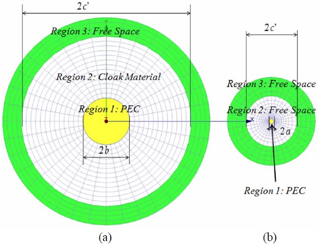
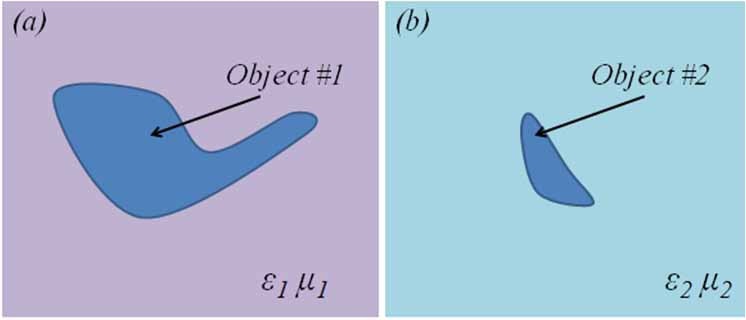
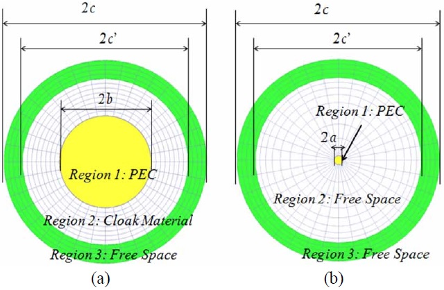
    To elaborate on the concept a little more, let us consider two objects belonging to physical and virtual domains, and shown in Fig. 1(a) and (b), respectively. The medium parameters surrounding these objects, namely (
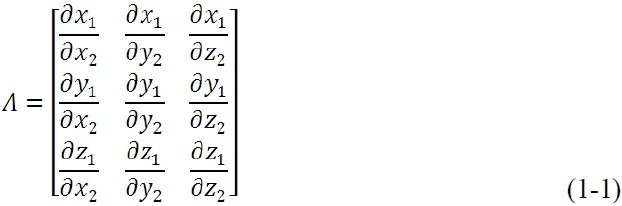
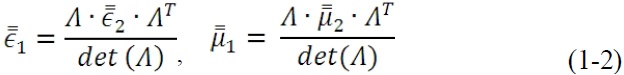
ε1, μ1) and (ε2, μ2), are also shown in Fig. 1. Now we pose the question: How can we relate the medium parameters in the two domains (physical and virtual) when we transform the geometry of object #1 in the physical domain into that of object #2 in the virtual domain via coordinate transformation. The answer to this question is surprisingly simple; in fact, the principle upon which the answer to it is based has been enunciated in a number of papers, dating back to almost fifty years ago, that have examined the behavior of Maxwell’s equations in a generalized curvilinear coordinate system. More recently, a number of authors, prominent among them Pendry et al. [1], Leonhart [2], Yang et al. [3], and Kwon and Werner [4], as well as several others [5-14], have presented the relationship between the material parameter (ε2, μ2) and (ε1, μ1), under the physical constraint that the electric and magnetic fields in the two domains remain “invariant” to the transformation between the two systems. The relationship can be explicitly stated as:

    image
    image

    where Λ represents the Jacobian matrix relating the two domains (x, y, and z can be arbitrary and curvilinear coordinates in general), ε and μ represent the permittivity and the permeability of the corresponding mediums, respectively. Eq. (1) enables us to navigate between the two systems and relate their material parameters in a unique, systematic and rigorous way.

    Pendry et al. [1], Schurig et al. [15], and a number of other workers [2-14,16-18] have leveraged the fact that the medium parameters can be related via (1), in order to lay the foundations of designing cloaks, which render a target invisible when covered by using materials whose parameters are dictated by the TO. We will now explain the basic principles of TO-based cloaking, which, in principle, can render an object totally invisible. Towards this end, we return to Fig. 1 and define the following task for ourselves: design the cloak (i.e., a cover or a blanket) for the perfect electric conductor (PEC) object in Fig. 1(a) such that it is invisible to an arbitrary incident field that impinges upon it. Note that no restriction is being placed on the frequency, polarization or the angle of incidence of the illuminating field in connection with this task.

    To solve the problem, posed above, we begin with a co-ordinate transformation, which morphs the object #1, which is located in the physical domain, and for which we are trying to design the cloak, into the object #2 residing in the virtual domain. Although this transformation is not obvious when the geometries of both the objects are totally arbitrary, it is nonetheless doable, at least theoretically. The caveat, though, is that the procedure provides us no guarantees that the materials parameters dictated by the transformation are physically realizable, and/or that they can be fabricated in practice to achieve cloak designs which satisfy the desired specifications, such as small thickness, wide bandwidth, polarization insensitivity, etc.

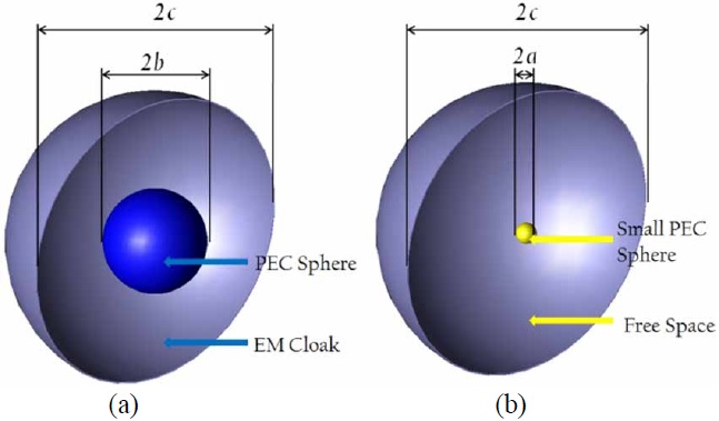
    The realizability issue, alluded to above, becomes even more critical when we attempt to design an “invisible” cloak, the so-called ‘holy grail’ of cloak designers. We will now explain why this is the case with a simple example shown in Fig. 2.

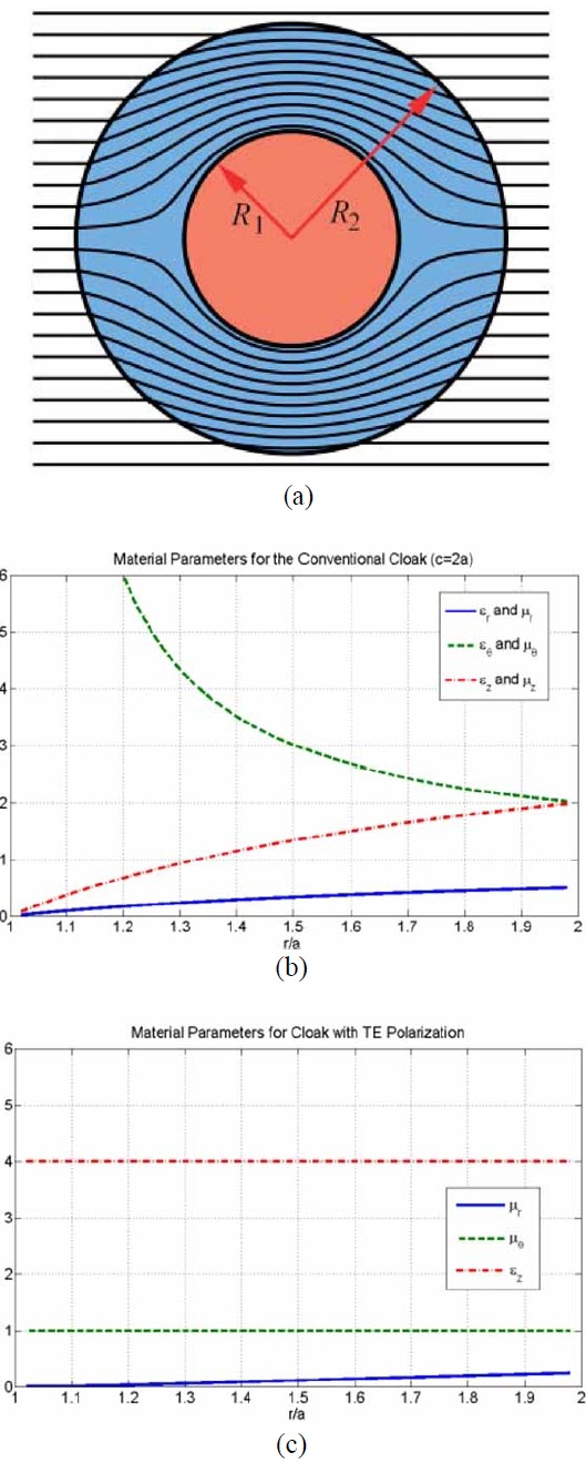
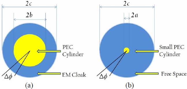
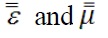
    Let us assume, for the sake of convenience, that the target we wish to cloak is a sphere and that we are going to follow the TO paradigm for this task. This problem has been extensively studied by a number of authors [1-22] and they have derived the material parameters for the cloak by invoking the TO, and using the Jacobian of the transformation (Eq. (1)), which makes the cloaked object totally disappear (become invisible). In Fig. 3 we plot the material parameters, presented in [18], which makes the cylinder (Fig. 3) invisible, at least in principle. We discuss this cylinder problem first, because the observations we make about the inherent difficulties encountered in the process of realizing a TO-based cloak for this two-dimensional (2D) geometry are also applicable, by and large, for the sphere problem, with only slight modifications.

    We observe several things from Fig. 3. First, we see that the material parameters are anisotropic, and this in of itself can be problematic when we attempt to realize them in practice, because there is no systematic method available for synthesizing them. The second thing we observe about the μ and ε values is that they vary over a wide range, tending to 0 in some regions and ∞ in others. Once again, this type of inhomogeneous behavior and a wide swing in the required material parameters as functions of the radial distance make it very difficult to realize them. In fact, we must resort to using metamaterials (aka artificially-engineered materials) that are notoriously narrowband, dispersive and lossy-undesirable attributes that degrade the performance of the cloak and render it unsuitable for most applications. What exacerbates the problem even more is the fact that the thickness of the cloak is comparable to the wavelength, rather than being a small fraction of the same. As we well know, a thin wrapper is desired in most applications, e.g., when designing stealth targets for the radar world.

    At this point we return to the TO paradigm for cloak designs and scrutinize it carefully to see if we can thresh out the root causes of the difficulties that we have just identified with the TO-based design, namely anisotropy, high degree of inhomogeneity, dispersive nature, and large thickness. Although we have not mentioned this before, it is worthwhile to add dependence on the polarization and sensitivity to the incident-angle to the list above, which further aggravate the situation.

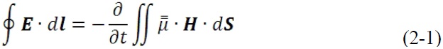
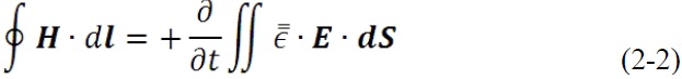
    Towards our quest to identify the problem areas with the TO-based cloak designs, we turn to an alternate derivation of the material parameters in the context of transformation electromagnetics. Rather than relying directly on the Jacobian of the transformation, which relates the Physical domain to the corresponding virtual domain, we turn to the integral forms of Maxwell’s equations appearing below:

    image
    image

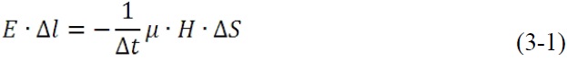
    Initially, we consider the relatively simple case where the two domains are simply related by scaling, say by a factor ‘γ’, as has been done in the previous TO-based cloak designs [18]. The method we propose to relate the material parameters in the two domains is very general and is applicable to the case where the two geometries have arbitrary shapes, and are not simply related to each other by a scale factor, as we will discuss later in Section III.

    To derive the material properties of the physical domain, from the assumed parameters in the virtual domain (ε0, μ0 for free-space in this example), we turn to Fig. 4 and Eq. (2). The next step, which is key to the TO-based algorithm, is to impose the condition that the fields (E1, H1) in the physical domain be “identical” to those in the virtual domain, i.e., (E2, H2). To facilitate the imposition of this condition, we now discretize the two domains, as shown in Fig. 5, by setting up a mesh to discretize the regions 2 and 3 in both domains. We take advantage of the circular symmetry of the geometries in the two domains, and of the fact that the geometry of the PEC cylinder, located in region-2 in the virtual domain is simply a scaled-down version of the one in the physical domain (region-1), and note that this transformation preserves the azimuthal symmetries of the two domains. In view of this, we use the same angular increments of Δ? in both domains, although we follow a different strategy in the radial direction, along which we impose the following three conditions:

    (i) The number of radial cells be identical in region-2 of the domains, which spans the radial distance b

    (ii) The cell size in the outermost boundaries of region- 2 is to be identical in the two-domains;

    (iii) The cell sizes in region-3 in both domains be identically equal in the radial direction, not only between c’

    There are logical reasons for imposing the above constraints, as we will now explain, before we proceed to derive the relationships between the material parameter distributions in the two domains. First, the TO must be applied to entire regions external to the PEC target-cylinder in this case-when relating the material parameters in the two domains, viz., b<r<∞ in the physical domain and a<r<∞ in the virtual model. Specifically, we cannot truncate the regions as we transform from one domain to another, without introducing discontinuities in the fields, and thus violating the premise of TO under which we are operating. If we use condition (iii), in Eq. (2), we immediately see that if the two fields as well as the mesh sizes would be identical in the two domains. It follows then, that the material parameters must be exactly the same in region-3 in the two domains. Since we have chosen the material parameters in the virtual domain in region-3 to be free-space, i.e., these parameters are ε0 and μ0, then region-3 in the physical domain must correspond to free-space as well, as would the parameters of the external region c’<r<∞. This is a crucial point, and it implies that the cloak in the physical domain has but a finite thickness, spanning the region b<r<c’. This is obviously necessary in order for the cloak design to be practical, since we cannot accept a cloak design whose thickness is infinite, as it would be if we did not impose the equal-mesh-size condition in the two domains in region-3 and beyond, i.e., for r>c’.

    image
    image

    where we are considering only the Ez and H components for this 2D geometry, namely a cylinder, for which z is along the axis of the cylinder, and ε and μ in Eq. (3) are the appropriate elements of the

    image

    tensors.

    Let us now turn to the regions-2 in the two domains, i.e., physical and virtual. Recall that we have imposed the condition that the cell size at the outermost boundary of this region be identical in the two domains, which guarantees that the transition of the material parameters would be smooth as we transition from region- 2 to region-3 (recall region-3 and beyond is freespace in both domains). So, all that remains to do now is to determine the material parameters of the cloak region in the physical domain, which spans from b<r<c’, by invoking the condition that the fields (E1, H1) of the physical domain be identical to the fields (E2, H2) in the virtual domain (which we have chosen to be free space), as well as condition (i) on the number of cells in the two domains associated with region-2, namely that this number be identical in the two domains. At this point, we impose an additional condition, without loss of generality, that the cell sizes in region-2 in the physical domain be identical in the radial direction, as we go from r=b to r=c’. Also, for the sake of discretization we choose the cell size in the radial direction to be λ /20, though there is no hard and fast rule that says that we must adhere to this last condition, which is dictated more by the numerical discretization of the integral forms of Maxwell’s Eq. (3), than by anything else. At this point, we note that since the dimensions of region-2 in the physical and virtual domains are different, we typically choose the radius a such that a<<b, in order to ensure that the scattering from the small cylinder in the virtual domain would be small-in fact vanishingly small in the ideal case-in order to render it invisible as a→0 in the limit. Note that we must choose a non-uniform mesh in the virtual domain, so that we can simultaneously satisfy condition (iii), as well as the constraint on the number of cells in the radial direction in the two domains, namely that they be equal. Though we have some flexibility in terms of the variation of the cell size in the radial direction in the virtual domain, we choose this variation in Δr to be smooth, and monotonically increasing in terms of the cell size as we go from r=a to r=c’, so that the summation of all the Δr’s equal (c’a). An example of such a mesh is shown in Fig. 6.

    Having defined the meshes in the two domains, we finally turn to the task of determining the material parameters of the cloak in the physical domain. Since we wish to impose the criterion that the two sets of fields, namely (E1, H1) and (E2, H2) in the two domains, respectively, be identical. Eq. (2) tells us that the (ε1, μ1) values in the physical domain, must be ε0/γn and μ0/γn where γn is the ratio of the areas of the nth cell in the physical and virtual domains, respectively. It is evident that, under these conditions, the ε1 and μ1 must start out at ε0/γ1 and μ0/γ1, where γ1 the ratio of the dimensions of the first cell (at r=b) in the physical domain to that of the dimension of its counterpart (at r=a) in the virtual domain. Also, we recall from our previous discussion, that ε and μ values are identical in both domains when we reach r=c’, and that they are both just (ε0, μ0).

    We now make two important observations. First, the cloak we have designed by following the procedure just described, which is based on the TO algorithm-though implemented differently than via the use of the Jacobian- has an inhomogeneous characteristic in the radial direction, albeit smooth. Second, the ε and μ values in the physical domain are larger, by a factor of 1/γ1, than their free-space counterparts. This factor is the bane of the TO-designed cloaks, since it calls for metamaterials to fulfill the requirements on the material parameters if we insist that the cloak must render the target totally “invisible”, since we can fulfill that condition if and only if a→0, in the strictest sense, and this implies that γ1 must also follow suit and tend to zero.

    We should mention that although we chose the simple geometry of the cylinder to identify the fundamental difficulties with the implementation of the TO paradigm, the problem with the realization of material parameters persists regardless of the geometry of the target, as long as we insist that it becomes invisible, which in turn requires that the scale factor (equivalent to γ) tends to 0.

    Before we discuss our strategy for overcoming this fundamental roadblock, we examine another fundamental limitation posed by the TO paradigm when we attempt to reduce the thickness of the cloak t (=c’b), to realistic values, e.g., a small fraction of the wavelength. We note that the material values (ε0, μ0) near the outer boundary of the cloak, located at r=c’, do not change, regardless of whether r is large or small, and, for that matter neither do the behaviors of (ε, μ) of the cloak in the neighborhood of r=b, where the above parameters →∞. While we can attempt to partially mitigate this problem by imposing a cap on the values of these parameters, we cannot change the fact that the relative εn and μn must reduce from very large values at the surface of the cylinder to unity within a relatively short distance; and this, in turn, again poses realizability problems in practice. For this reason, practical realizability of thin invisibility cloaks have not met with too much success in the past, and is unlikely that the thickness issue will be resolved anytime soon if we continue to impose the above invisibility criterion on the TO-based cloak designs. Fig. 7 shows the deterioration of the performance of the cloak (Fig. 7(c) when we design a thin three-layer cloak by using discretized values of the cloak parameters, which vary continuously from r=b to r=c’). It is evident that the wavefront of the field becomes considerably distorted when we compare the performance of the thin cloak with the ideal one the results for which are included in Fig. 7(b) for comparison.

    We now proceed to outline a strategy for designing coatings for radar targets which circumvent the various problems identified above, when attempting to realize realistic cloak designs.

    Ⅲ. RCS Reduction for Practical Targets by Using the Concepts of TO

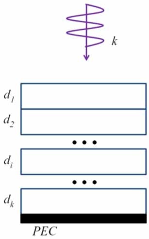
    Our strategy is to follow a three-step process, which we will now outline below. Our first step is to design wideband layered absorbers for infinite, planar, conducting ground planes. We note that this is also the basic approach to designing coating for radar targets to render them stealthy, regardless of their shapes and that it is relatively easy to carrying out this design by using optimization algorithms to determine the material properties and the layer thicknesses to reduce the reflection from the coated PEC plane, say, below ―10 dB level, and over a wide frequency band, say covering the radar frequencies from 2 to 18 GHz, as typical examples (note that this is in contrast to 2%-3% bandwidth of cloaks designed by using the legacy TO algorithm).

    A typical cost function to be minimized, which is suitable for optimizing the layer thicknesses and material parameters can be defined as follows:
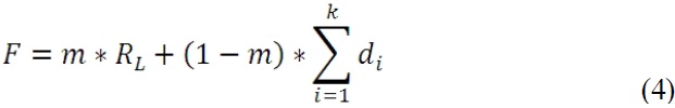
    image

    where di represents the thickness for each layer of the absorber; RL stands for the reflection level at the air-absorber interface and is a function of the material parameters and thicknesses di of the absorbing layers (Fig. 8); and m is the weight of the reflection level in the optimization, signifying the importance of the reflection level over the collective thickness of the layered absorber, m=1 corresponds to the case where the total thickness is predetermined, and only the reflection coefficient is minimized. Note that the material parameters are dispersive, and hence the optimization to determine the thicknesses should be carried out over the entire desired frequency band.

    Besides the wide bandwidth, there are two other important attributes which distinguish this type of blanket design from the traditional TO cloaks. The first of these is that the proposed blankets are relatively insensitive to polarization as well as the incident angle of the impinging radar signal interrogating the target. This is in contrast to the TO-designed cloaks [18], which become rapidly ineffective if either the polarization or the incident angle deviates from that of the combination of the two parameters for which the TO-cloak was designed.

    The second attribute of the present design is perhaps even more crucial than the first one we mentioned above, and this concerns the availability of the materials needed to design the blanket, which, as we might recall, posed serious realizability problems, owing to the unrealistically large (or small) parameter values (Fig. 3) demanded by the TO algorithm.

    As is well known, the radar absorbing materials (RAMs) have been around for a very long time, some for many decades, dating back to when stealth aircrafts came into vogue in the sixties, and perhaps even before. Although information on these RAM materials is not available openly because of their “classified” or “secret” nature, understandably so because they are used in military applications to design stealth aircrafts and missiles, a plethora of information about similar absorbing materials is nonetheless available in the open literature, including the details of their fabrication, which have been described in [23,24], for instance.

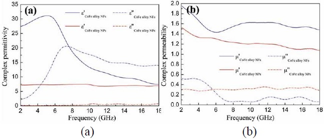
    Here we will use two different types of materials namely CoFe nano-flakes (NF) and CoF enano-particles (NP), whose frequency variations are shown in Fig. 9. We point out that these materials can be realized with relative ease, as is evident from [27,28], where the details of their fabrication can be found.

    We note that the ε and μ values of these materials are both complex and that they do vary with frequency; hence they are dispersive. We hasten to point out, however, that unlike the metamaterials, which typically have variations with frequency because of resonant inclusions they use to achieve effective ε and μ values that are very high, very low, or even negative, the material parameters of the NP and NF materials vary relatively smoothly with frequency, and this is crucial for realizing wideband performance, as we will soon see.

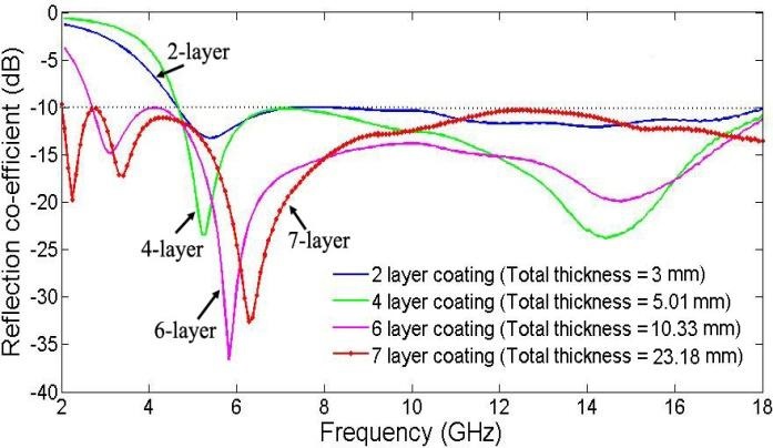
    To illustrate the fact that we can indeed achieve wideband performance in terms of reflection reduction over a wide frequency band with relative small thicknesses of 2, 4, 6 and 7 layer absorbers we refer to Fig. 10. Although not shown here, the results for the reflection coefficient reduction are also satisfactory when either the polarization, or the incident angle is varied and this is also true when both are changed simultaneously.

    The performance characteristics of several multilayered absorbers, designed by using the above materials, are presented in Fig. 10 for a 10 dB (or better) reduction in the reflection coefficient over the frequency range of 2-18 GHz.

    We now move to the second step in our design procedure, which is to adapt the blanket designed for the infinite PEC plane to an arbitrarily shaped object. Initially we consider an object with a smooth surface whose radius of curvature is moderate-to-large everywhere. We will generalize the procedure in the third step, using the principles of the TO when the above assumption regarding the smoothness of the object is not valid, as for instance when the object has sharp edges or bumps, as a general target would in practice.

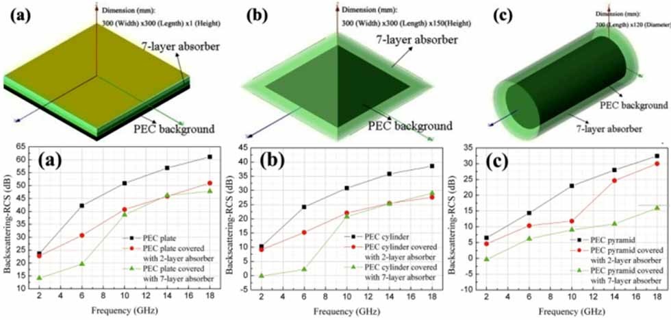
    When the object has a relatively smooth geometry, we initially wrap the multilayer absorbing blanket, which we have designed earlier for the planar surface around the PEC target whose scattering cross-section we are attempting to reduce, and test the effectiveness of the blanket for the new object. For a wide variety of targets we have examined, a number of which are shown in Fig. 11, we have found that the blanket does reduce the monostatic as well as the bistatic RCS in the “reflection” region near the surface of the object for different angles of incidence and polarizations of the incoming wave. The results for a two-layer absorber are shown in Figs. 12 and 13 for a rectangular cylinder of finite length, which we have studied as a test case.

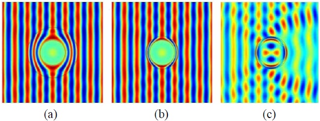
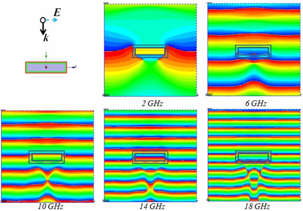
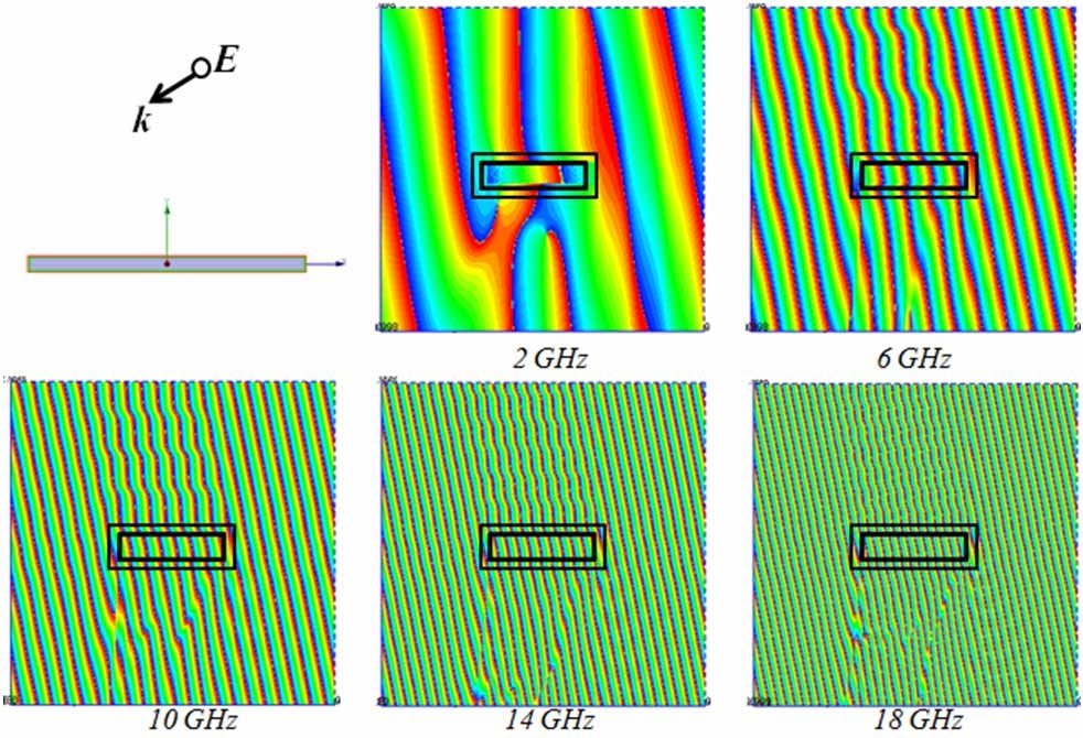
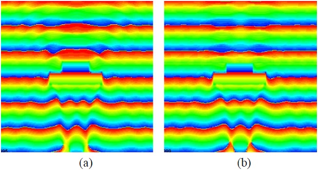
    A simple test, which is typically applied to cloak designs, is to examine the wavefront of the total (incident+ scattered) field, and see how the level of distortion of the wavefront decreases when the scatterer is covered by the layered absorbing blanket. We present the plots of these wavefronts of the total fields for normal and oblique incidence cases in Figs. 12 and 13, respectively.

    We observe that the object, which is a finite cylinder of height 18 cm, generates distorted wavefronts owing to the contribution of the scattered field from the object, even when covered by a two-layer blanket, designed for the infinite planar PEC object, for the nominal frequency range of 4.6-18 GHz, with a nominal reflection coefficient of ―10 dB or less. However, we also note from Fig. 12 that the distortion in the phase front is relatively small once we got above the low-end of the design frequency range, viz., 4.6 GHz for the planar geometry, confirmingplanar design performs reasonably well even though we are dealing with a rectangular cylinder now. We hasten to point out that the results presented in Fig. 12 are not for a blanket which has been optimized for the object at hand, and we expect some compromise in the performance of the cloak. However, we can improve this performance by optimizing the parameters of the two-layer design, specifically the relative thicknesses of the two-layer, even as we maintain the total thickness intact. We expect the changes to be relatively minor, however, except for the corner regions and, hence, the optimization process should be realistic as well as numerically feasible. The above remarks are also applicable to the oblique incidence case, for which some sample results are presented in Fig. 13.

    It is important to point out that the strategy for designing the absorbing blanket, presented herein, is very different from that employed for ideal traditional TO cloak, since the latter is designed to render the (object+cloak) composite to have a zero scattering cross-section in all directions, whereas the blanket design introduced here seeks to reduce both backscattering and bistatic scattering scenarios but only in the reflection region, and not in the forward-scattering direction. We hasten to point out, however, that this type of performance is perfectly well suited for modern radar systems, symbolically depicted in Fig. 14 above, where only the scattering in the reflection region is of concern.

    For the final step, we consider the problem of absorber design when a shape perturbation is introduced in an object. Let us say that our modified target is the same rectangular cylinder we just considered above, except for a bump on the top surface. The extra corners introduced by the perturbation, be they smooth or sharp, would obviously introduce distortions in the planar phase front, and potentially increase the scattering level. Our objective here is to restore the field behaviour so that it is close to that of the original object that we had prior to the introduction of the perturbation.

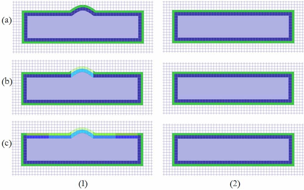
    We now outline the procedure for the blanket design for the new object, shown on the left in Fig. 15, i.e., Fig. 15(1), which is in the physical domain, and is a modified version of the one shown in the right side of the same figure; i.e., Fig. 15(2), which corresponds to the virtual domain. Note that unlike the cylinder example we discussed earlier, the medium in the virtual domain, surrounding the object, is no longer free-space, as was the case shown in Fig. 6. Note also that the dimensions of the objects in the two domains are comparable, and are totally different from the legacy TO-design case, in which the scale factor between the dimensions of the object in the physical and virtual domains tends to infinity to render the target invisible.

    To find the parameters of the cloak for the modified geometry in Fig. 15, we revisit the integral forms of Maxwell’s Equations, presented earlier in Eq. (2), to relate the material parameters associated with the two systems shown in the figure. Fig. 15(1) shows the physical system with locally modified medium parameters for the perturbed object, while Fig. 15(2) depicts the virtual system with the original medium parameters covering the unperturbed object. The field distribution near the perturbed object would obviously be different from that of its unperturbed counterpart, since the perturbation introduces additional scattering to the incoming wave. We link the change in the field with the modification in the geometry, and then compensate it by the changing the medium parameters. Given the specific profile of the perturbation and the simulated field distributions, the only unknowns, namely the medium parameters, can be derived as follows:
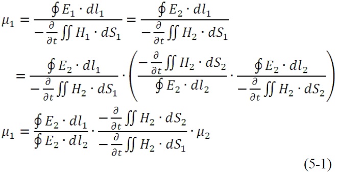
    image

    and

    image

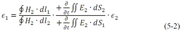
    where, once again, for the sake of simplicity, we have used scalar quantities in Eq. (5) as though the geometry under consideration is two-dimensional, which it is in the present example, and we would need to replace the field quantities with vectors and the material parameters with tensors for the general 3D case.

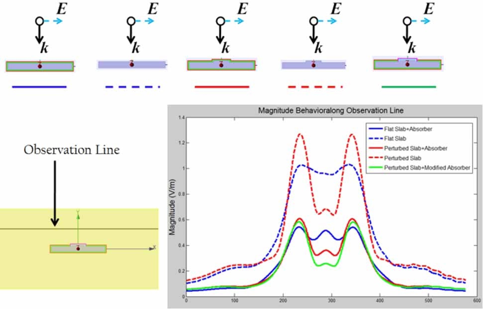
    The field behaviors for the perturbed object with locally modified material parameters can be seen from Figs. 16 and 17. Fig. 16 shows that the amplitude of the scattered E-field is reduced, and that the phase front of the total E-field is approximately restored as well in the reflection region.

    Fig. 17 compares the amplitudes of the scattered electric fields for five different scenarios listed below:

    (a) The flat slab

    (b) Flat slab + absorber

    (c) Perturbed slab

    (d) Perturbed slab + initial absorber

    (e) Perturbed slab + modified absorber

    We should clarify the fact that although we are referring to this geometry as a slab, what we are really dealing with is a wide rectangular cylinder, with a small thickness.

    We note that the modified slab does introduce additional scattering, and that the absorber does help reduce the same. We also note that the modified absorber improves the performance over the initial one, but only slightly, which shows that the planar version of the cloak is not all that inferior to the one modified for this type of geometry. Additional optimization of the modified cloak is expected to improve the performance even further, if so desired.

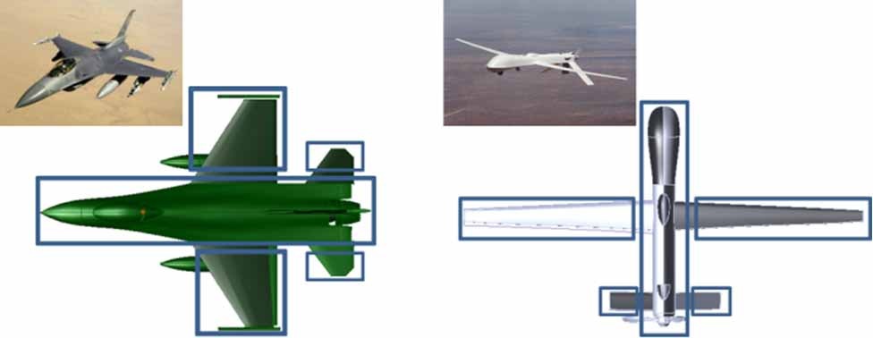
    For an arbitrary target, we can first decompose the geometry of the target in a manner illustrated in Fig. 18, and wrap each part of the target with an absorber, designed by using the approach based on shape perturbation of a related smooth object, and then follow the methodology we have described above to determine the material parameters of the shroud. It should be evident that this is a far more realistic approach than transforming the geometries of these complex objects into an infinitesimally small-size target, as called for by the TO algorithm for cloak designs, and following the TO recipe corresponding to such a geometry transformation, which is bound to lead to unrealistic and impractical designs.

    Finally, we mention that we need to extend the procedure outlined above when dealing with an arbitrary target, though the basic philosophy of the design procedure remains the same.

       1. Reduction of Radio Frequency Interference (RFI)

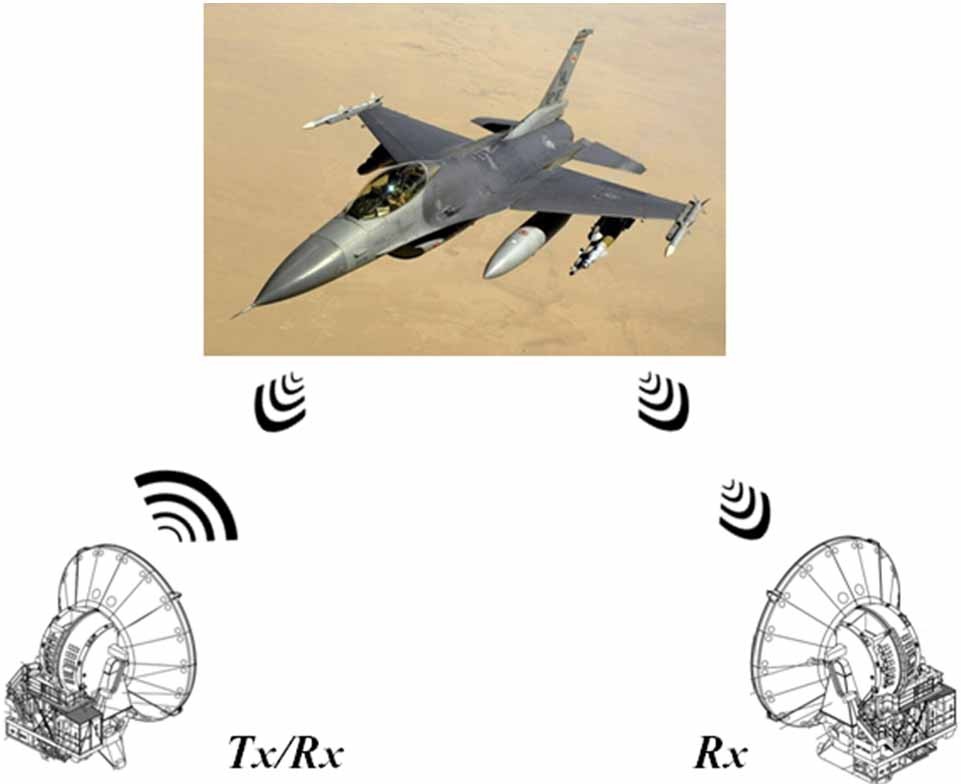
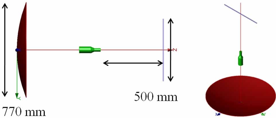
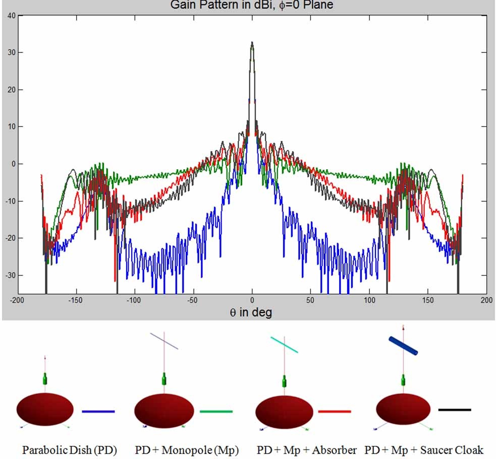
    Reduction of RFI, another important application for the absorber-wrapping is to mitigate the problem of antenna blockage in a shared-platform environment, as shown in Fig. 18, in which the introduction of the aggressor antenna can raise the far-end sidelobe levels of the parabolic dish significantly. To mitigate this effect, we can wrap the monopole by using a multilayer absorber which has been optimized for a planar geometry, as we have done in the past, or we can optimize the layer thicknesses and material parameter for the circular cylinder geometry. Alternatively, we can use a conducting saucer-like structure wrapped around the monopole, as proposed in [25-27]. Figs. 19 and 20 show the model used to construct the alternative cloak with the monopole as the cloaked target. Fig. 21 shows the far field patterns of a parabolic dish antenna-the victim antenna- when a monopole, which is the aggressor antenna, is placed in the vicinity of the dish. The patterns of the dish/monopole composite are also included in the figure for two treatment plans applied to the aggressor antenna. We note that the introduction of the absorber treatment reduces the sidelobe levels of the dish antenna, as compared to the case for the far-end antenna combination without the treatment.

    However, we also note that an elaborate cloak design, shown in Fig. 20, which is apparently inspired by the TO, isn’t really needed, and that we can do just as well with a thin absorber type of wrapper.

    Recent advances in material engineering and research in graphene-based absorbing materials also broadens the choice of the materials used for the absorber designs discussed in this paper. Graphene-based absorbing materials generate sufficient level of magnetic loss without the need to introduce magnetic metals like Co, Fe, and Ni. These new materials also have the advantage of being lightweight, and thin, that are highly desired attributes for airborne applications. There have been reported cases of achieving below ―70 dB reflection level shielding with 2.09 mm of grapheme nanoplatelet-synthesized material [28], as well as below ―20 dB reflection level over the entire 4.5-18 GHz with 8 mm of multilayered carbon nanotube fabric [29].

    The performance of the absorbers can also be enhanced by introducing frequency structure surface (FSS)-type structures within the layers, which add virtually no extra thickness to the composite structure. The FSS structures can be tailored to enhance the absorbance in target frequency bands [30] or to broaden the working bandwidth [29] of the initial layered absorber.

    Ⅳ. Conclusion

    In this paper we have presented a strategy for designing cloaks and absorbing blankets for scattering reduction which deviates from the classical TO algorithm. We have discussed the limitations of the Transformation Optics-based algorithm, which typically calls for metamaterials for cloak designs, that are not available in nature and suffer from problems of narrow bandwidths, high losses, unacceptable levels of polarization and incident- angle sensitivities, etc., when synthesized artificially. We have provided an alternative approach to TO for relating the material parameters of the physical and virtual domains, by using the integral forms of Maxwell’s equations. We have used this new perspective to identify the root cause of the difficulty that arises when designing cloaks by using the TO, namely inability to realize extreme values of the material parameters called for by the TO algorithm

    Following this we have shown how we can use the technique of Impedance Transformation, as a first step, to develop absorbing blankets for infinite structures, and then use it as a stepping stone for designing absorbing blankets for objects of arbitrary shape.

    Finally, we have detailed an algorithm for deriving the material parameters of absorbing blankets, for arbitrarily shaped objects, to reduce their scattering levels in the reflection region, over a wide frequency band, and for wave incidences with arbitrary polarization and incident angles. A number of examples have been included to illustrate the performances achieved by the absorbing blankets designed by using the developed technique. The interested reader may refer to the publications appearing in [31-35] for related information on the topic discussed in this work.

참고문헌
  • 1. Pendry J. B., Schurig D., Smith D. R. 2006 "Controlling electromagnetic fields" [Science] Vol.312 P.1780-1782 google cross ref
  • 2. Leonhardt U. 2006 "Optical conformal mapping" [Science] Vol.312 P.1777-1780 google cross ref
  • 3. Yang R., Tang W., Hao Y. 2011 "A broadband zone plate lens from transformation optics" [Optics Express] Vol.19 P.12348-12355 google cross ref
  • 4. Kwon D. H., Werner D. H. 2010 "Transformation electromagnetics: an overview of the theory and applications" [IEEE Antennas and Propagation Magazine] Vol.52 P.24-46 google cross ref
  • 5. Ruan Z., Fan S. 2010 "Superscattering of light from subwavelength nanostructures" [Physical Review Letters] Vol.105 P.013901 google cross ref
  • 6. Ergin T., Stenger N., Brenner P., Pendry J. B., Wegener M. 2010 "Three-dimensional invisibility cloak at optical wavelengths" [Science] Vol.328 P.337-339 google cross ref
  • 7. Chen H. Y., Chan C. T. 2007 "Transformation media that rotate electromagnetic fields" [Applied Physics Letters] Vol.90 P.241105 google cross ref
  • 8. Leonhardt U., Philbin T. G. 2009 "Transformation optics and the geometry of light" [Progress in Optics] Vol.53 P.69-152 google
  • 9. Chen H., Chan C. T., Sheng P. 2010 "Transformation optics and metamaterials" [Nature Materials] Vol.9 P.387-396 google cross ref
  • 10. Huidobro P. A., Nesterov M. L., Martin-Moreno L., Garcia-Vidal F. J. 2010 "Transformation optics for plasmonics" [Nano Letters] Vol.10 P.1985-1990 google cross ref
  • 11. Edwards B., Alu A., Silveirinha M. G., Engheta N. 2009 "Experimental verification of plasmonic cloaking at microwave frequencies with metamaterials" [Physical Review Letters] Vol.103 P.153901 google cross ref
  • 12. Alu A., Engheta N. 2005 "Achieving transparency with plasmonic and metamaterial coatings" [Physical Review E] Vol.72 P.016623 google cross ref
  • 13. Luo Y., Zhang J., Chen H., Xi S., Wu B. I. 2008 "Cylindrical cloak with axial permittivity/permeability spatially invariant" [Applied Physics Letters] Vol.93 P.033504 google cross ref
  • 14. Xi S., Chen H., Zhang B., Wu B. -I., Kong J. A. 2009 "Route to low-scattering cylindrical cloaks with finite permittivity and permeability" [Physical Review B] Vol.79 P.155122 google cross ref
  • 15. Schurig D., Pendry J. B., Smith D. R. 2006 "Calculation of material properties and ray tracing in transformation media" [Optics Express] Vol.14 P.9794-9804 google cross ref
  • 16. Cummer S. A., Popa B. I., Schurig D., Smith D. R., Pendry J. B. 2006 "Full-wave simulations of electromagnetic cloaking structures" [Physical Review E] Vol.74 P.036621 google cross ref
  • 17. Li J., Pendry J. B. 2008 "Hiding under the carpet: a new strategy for cloaking" [Physical Review Letters] Vol.101 P.203901 google cross ref
  • 18. Schurig D., Mock J. J., Justice B. J., Cummer S. A., Pendry J. B., Starr A. F., Smith D. R. 2006 "Metamaterial electromagnetic cloak at microwave frequencies" [Science] Vol.314 P.977-980 google cross ref
  • 19. Valentine J., Li J., Zentgraf T., Bartal G., Zhang X. 2009 "An optical cloak made of dielectrics" [Nature Materials] Vol.8 P.568-571 google cross ref
  • 20. Leonhardt U., Tyc T. 2009 "Broadband invisibility by non-Euclidean cloaking" [Science] Vol.323 P.110-112 google cross ref
  • 21. Chen H., Wu B. I., Zhang B., Kong J. A. 2007 "Electromagnetic wave interactions with a metamaterial cloak" [Physical Review Letters] Vol.99 P.063903 google cross ref
  • 22. Smith D. R., Urzhumov Y., Kundtz N. B., Landy N. I. 2010 "Enhancing imaging systems using transformation optics" [Optics Express] Vol.18 P.21238-21251 google cross ref
  • 23. Gong Y. X., Zhen L., Jiang J. T., Xu C. Y., Shao W. Z. 2009 "Synthesis and microwave electromagnetic properties of CoFe alloy nanoflakes prepared with hydrogen-thermal reduction method" [Journal of Applied Physics] Vol.106 P.064302 google cross ref
  • 24. Zhen L., Gong Y. X., Jiang J. T., Xu C. Y., Shao W. Z., Liu P., Tang J. 2011 "Synthesis of CoFe/ Al2O3 composite nanoparticles as the impedance matching layer of wideband multilayer absorber" [Journal of Applied Physics] Vol.109 P.07A332-07A334 google cross ref
  • 25. Tretyakov S., Alitalo P., Luukkonen O., Simovski C. 2009 "Broadband electromagnetic cloaking of long cylindrical objects" [Physical Review Letters] Vol.103 P.103905-103908 google cross ref
  • 26. Alitalo P., Tretyakov S. A. (2010) "Electromagnetic cloaking of strongly scattering cylindrical objects by a volumetric structure composed of conical metal plates" [Physical Review B] Vol.82 P.245111-245114 google cross ref
  • 27. Vehmas J., Alitalo P., Tretyakov S. A. 2012 "Experimental demonstration of antenna blockage reduction with a transmission-line cloak" [IET Microwaves, Antennas & Propagation] Vol.6 P.830-834 google cross ref
  • 28. De Bellis G., De Rosa I. M., Dinescu A., Sarto M. S., Tamburrano A. 2010 "Electromagnetic absorbing nanocomposites including carbon fibers, nanotubes and grapheme nanoplatelets" [in Proceedings of the IEEE International Symposium on Electromagnetic Compatibility] P.202-207 google
  • 29. Tellakula R. A., Varadan V. K., Shami T. C., Mathur G. N. 2004 "Carbon fiber and nanotube based composites with polypyrrole fabric as electromagnetic absorbers" [Smart Materials & Structures] Vol.13 P.1040-1044 google cross ref
  • 30. Zhou Y., Mittra R. 2012 "Performance enhancement of RF absorbers by using resistively-loaded periodic screens" [in Proceedings of the IEEE Antennas and Propagation Society International Symposium] P.1-2 google
  • 31. Cheng Q., Cui T. J., Jiang W. X., Cai B. G. 2010 "An omnidirectional electromagnetic absorber made of metamaterials" [New Journal of Physics] Vol.12 P.063006 google cross ref
  • 32. Mittra R., Zhou Y., Mittra R. 2013 "Designing cloaks and absorbing blankets for scattering reduction using field and impedance transformation techniques" [in Computational Electromagnetics: Recent Advances and Engineering Applications] google
  • 33. Ozgun O., Kuzuoglu M. 2007 "Electromagnetic metamorphosis: reshaping scatterers via conformal anisotropic metamaterial coatings" [Microwave and Optical Technology Letters] Vol.49 P.2386-2392 google cross ref
  • 34. Ozgun O., Kuzuoglu M. 2007 "Utilization of anisotropic metamaterial layers in waveguide miniaturization and transitions" [IEEE Microwave and Wireless Components Letters] Vol.17 P.754-756 google cross ref
  • 35. Teixeira F. L. 2007 "Closed-form metamaterial blueprints for electromagnetic masking of arbitrarily shaped convex PEC objects" [IEEE Antennas and Wireless Propagation Letters] Vol.6 P.163-164 google cross ref
OAK XML 통계
이미지 / 테이블
  • [ Fig. 1. ]  (a) Physical and (b) virtual domains used in the transformation optics algorithm.
    (a) Physical and (b) virtual domains used in the transformation optics algorithm.
  • [ Fig. 2. ]  Transformation optics-based cloak schematics and corresponding materials in the (a) physical geometry and (b) virtual geometry. PEC=perfect electric conductor, EM=electromagnetic.
    Transformation optics-based cloak schematics and corresponding materials in the (a) physical geometry and (b) virtual geometry. PEC=perfect electric conductor, EM=electromagnetic.
  • [ Fig. 3. ]  (a) Schematics for a cloaked perfect electric conductor cylinder with R2=2R1, (b) material parameters for an all-angle, all-polarization cloak, and (c) material parameters for an normal-incident, transverse electric (TE)-polarization cloak. Adapted from [18].
    (a) Schematics for a cloaked perfect electric conductor cylinder with R2=2R1, (b) material parameters for an all-angle, all-polarization cloak, and (c) material parameters for an normal-incident, transverse electric (TE)-polarization cloak. Adapted from [18].
  • [ Fig. 4. ]  Transformation optics-based cloak schematics and corresponding materials in the (a) physical geometry and (b) virtual geometry. PEC=perfect electric conductor, EM=electromagnetic.
    Transformation optics-based cloak schematics and corresponding materials in the (a) physical geometry and (b) virtual geometry. PEC=perfect electric conductor, EM=electromagnetic.
  • [ Fig. 5. ]  Cloak problem with mesh schematics: (a) physical and (b) virtual domains.
    Cloak problem with mesh schematics: (a) physical and (b) virtual domains.
  • [ Fig. 6. ]  Cloak problem with mesh schematics: (a) physical and (b) virtual domains. PEC=perfect electric conductor.
    Cloak problem with mesh schematics: (a) physical and (b) virtual domains. PEC=perfect electric conductor.
  • [ Fig. 7. ]  Field distribution for a perfect electric conductor cylinder in (a) an ideal transformation optics (TO) cloak, (b) an ideal, thin TO cloak, (c) a 3-layered TO cloak in which the medium parameters at each layer correspond to those of the ideal thin cloak.
    Field distribution for a perfect electric conductor cylinder in (a) an ideal transformation optics (TO) cloak, (b) an ideal, thin TO cloak, (c) a 3-layered TO cloak in which the medium parameters at each layer correspond to those of the ideal thin cloak.
  • [ Fig. 8. ]  Model schematics of the optimization problem for the multilayer absorber. PEC=perfect electric conductor.
    Model schematics of the optimization problem for the multilayer absorber. PEC=perfect electric conductor.
  • [ Fig. 9. ]  Real and imaginary parts of the (a) permittivity and (b) permeability for the two types of absorbing materials used in the multi-layer absorbing blanket design.
    Real and imaginary parts of the (a) permittivity and (b) permeability for the two types of absorbing materials used in the multi-layer absorbing blanket design.
  • [ Fig. 10. ]  Reflection coefficient of multilayer absorber backed by a perfect electric conductor plate for different number of layers.
    Reflection coefficient of multilayer absorber backed by a perfect electric conductor plate for different number of layers.
  • [ Fig. 11. ]  Back-scattering radar cross section of perfect electric conductor objects: (a) plate, (b) pyramid, and (c) cylinder covered with 2- and 7-layer absorbers.
    Back-scattering radar cross section of perfect electric conductor objects: (a) plate, (b) pyramid, and (c) cylinder covered with 2- and 7-layer absorbers.
  • [ Fig. 12. ]  Phase behavior of the E-field near the rectangular perfect electric conductor cylinder, which is wrapped around by an absorber blanket, normally incident on the cylinder.
    Phase behavior of the E-field near the rectangular perfect electric conductor cylinder, which is wrapped around by an absorber blanket, normally incident on the cylinder.
  • [ Fig. 13. ]  Phase behaviors of the E-field near the rectangular perfect electric conductor cylinder, which is wrapped around by an absorber blanket, for an obliquely incident plane wave.
    Phase behaviors of the E-field near the rectangular perfect electric conductor cylinder, which is wrapped around by an absorber blanket, for an obliquely incident plane wave.
  • [ Fig. 14. ]  Target detection in conventional radar scenarios: monostatic and bistatic schemes.
    Target detection in conventional radar scenarios: monostatic and bistatic schemes.
  • [ Fig. 15. ]  (a) Original 2-layer absorber wrapped around a rectangular cylinder with shape perturbation (left); (b) 2-layer absorber with transformation optics (TO)- modified material properties around regions with the shape perturbation (left); and (c) 2-layer absorber with TO modified material properties for all regions (left) and 2-layer absorber wrapped around a rectangular cylinder (right).
    (a) Original 2-layer absorber wrapped around a rectangular cylinder with shape perturbation (left); (b) 2-layer absorber with transformation optics (TO)- modified material properties around regions with the shape perturbation (left); and (c) 2-layer absorber with TO modified material properties for all regions (left) and 2-layer absorber wrapped around a rectangular cylinder (right).
  • [ Fig. 16. ]  Phase behavior of scattered E-field for (a) perturbed object wrapped by blanket with original medium parameter, (b) perturbed object wrapped by blanket with locally modified medium parameter.
    Phase behavior of scattered E-field for (a) perturbed object wrapped by blanket with original medium parameter, (b) perturbed object wrapped by blanket with locally modified medium parameter.
  • [ Fig. 17. ]  Comparison of the amplitudes of electric fields scattered by different objects.
    Comparison of the amplitudes of electric fields scattered by different objects.
  • [ Fig. 18. ]  Possible domain decomposition of two aircrafts: F- 16 Falcon fighter jet (left) and Predator Drone UAV (right) for scattering-reduction treatment.
    Possible domain decomposition of two aircrafts: F- 16 Falcon fighter jet (left) and Predator Drone UAV (right) for scattering-reduction treatment.
  • [ Fig. 19. ]  Model schematics for the blockage problem: (left) side view and (right) isometric view of the victim antenna (parabolic dish) and the aggressor antenna (monopole) sharing the same platform.
    Model schematics for the blockage problem: (left) side view and (right) isometric view of the victim antenna (parabolic dish) and the aggressor antenna (monopole) sharing the same platform.
  • [ Fig. 20. ]  Model schematics for the alternative cloak.
    Model schematics for the alternative cloak.
  • [ Fig. 21. ]  Radiation patterns for the antenna blockage problem: (blue line) dish antenna, (green line) dish antenna and the monopole antenna in the vicinity, and (red line) dish antenna with absorbertreated monopole antenna.
    Radiation patterns for the antenna blockage problem: (blue line) dish antenna, (green line) dish antenna and the monopole antenna in the vicinity, and (red line) dish antenna with absorbertreated monopole antenna.
(우)06579 서울시 서초구 반포대로 201(반포동)
Tel. 02-537-6389 | Fax. 02-590-0571 | 문의 : oak2014@korea.kr
Copyright(c) National Library of Korea. All rights reserved.