The term of ultra-wideband or UWB system has been synonymously associated with terms such as: impulse, carrier-free, baseband, time-domain, non-sinusoidal, orthogonal function and large-relative-bandwidth radio/radar systems. Since the late 1960s, the technologies related to UWB such as transmitters, receivers, radio frequency (RF) signals, antennas and systems have been presented and developed for radio and radar systems, in particular, for military applications. The basic feature of the UWB system is the occupancy of extremely wide operating bandwidth due to the use of impulse signals as compared with conventional radio systems.
In February 2002, the Federal Communication Commission (FCC) of United States opened a spectrum of 3.1-10.6 GHz but with a limited emission level of lower than ―41.3 dBm/MHz for commercial communication, imaging, and radar applications [1]. Different from the previous UWB systems, the spectrum can be occupied by single or a few pulses or divided into multiple sub-bands, each of bandwidths larger than 500 MHz.
The technology based on such a wideband bandwidth offers the great opportunity for achieving high-speed wireless communications and high-accuracy detections in principle. For example, the high speed wireless connections are expected to reach the data rate which is higher than 110 Mbps or even up to 480 Mbps with very short range wireless connections, typically around 10 m.
Such UWB-based wireless communication systems are promising in consumer electronics, especially for handset- centric applications and home networks. For example, we can embed such a technology into next generation wireless universal serial bus (USB) dongles or Bluetooth in order to achieve extremely high-speed wireless connections between devices in home or offices, such as laptops and digital cameras, high-definition (HD) TV sets, high-speed printers, and so on. However, the ultra-low emission power limits and high-speed data transmission cause technical challenges in the implementation of systems. One of the top challenges is the design of antennas to cover the extremely wide operating bandwidth.
The antennas with broadband even frequency-independent characteristics have been well developed for decades, for example, transverse electromagnetic mode (TEM) horns [2-4], self-complementary log-periodic structures [5,6], bi-conical antennas [7] and its variations [8-12], and cylindrical antennas with resistive loading [13,14]. However, as mentioned above, the new UWB technology will more focus on the consumer electronic devices for short-range wireless connections. Thus, the antennas mentioned above are too bulky to use in portable or/and mobile devices. Furthermore, the design considerations for antennas in the UWB wireless communications must be based on unique system requirements [15]. The antenna designs should be evaluated by not only antenna but also system parameters such as system transfer functions in terms of system gain and group delay, in particular, for the pulsed systems, even in time-domain.
The research and development of UWB antennas in the past decade has already focused on the three top design challenges: ultra-wideband operation, small size, and low cost [15].
2.1 Challenge 1: Ultra-Wideband Operation
In order to achieve an extremely wide operating bandwidth, antennas will be designed to cover either the entire UWB band of 3.1-10.6 GHz (110%) or the lower or upper UWB bands of 3.1-4.8 GHz (43%) or 6-10.6 GHz (55%), respectively, at least in terms of impedance matching.
Also, the radiation performance of the antennas should be consistent with the acceptable gain and unchanged polarization along the desired transmission or reception direction across the whole operating bandwidth in order to avoid the big change in received signals or energy. The consistent radiation beamwidths are also important to ensure the good communication coverage and localization accuracy.
In particular, the linear phase response is very important to reduce the distortion of the waveforms of received pulses in a pulsed based UWB system because a non-linear phase response will result in the severe distortion of waveforms of the received pulsed signals despite the good impedance matching and consistent gain across the operating bandwidth.
In short, the design challenge involves in the consistent characteristics of antennas in terms of not only impedance matching but also the radiation and phase responses over the desired ultra-wide bandwidth as required by UWB systems.
This challenge is caused by the fact that the majority of UWB-enabled systems are usually embedded into portable/ mobile consumer electronic devices. Physically, the antenna must be small-sized and easy to integrate with other circuits in order to keep the overall size of the device as small as possible. Such a requirement will directly lead to the design of electrically small antennas. First, the size of the antenna is smaller than the operating wavelength at the lower edge frequency of the operating bandwidth, for example, 100 mm at 3.1 GHz for the operating bandwidth of 3.1-10.6 GHz or 3.1-4.8 GHz. Currently, the maximal dimension of a monopole- type UWB antenna itself including the ground plane below it is about 25 mm×25 mm (a quarter-wavelength at 3 GHz). The UWB antennas with the size smaller than the quarter-wavelength will have the same design challenges as any of electrically small antennas such as possible narrow operating bandwidth, low gain/ radiation efficiency and difficult impedance matching.
In addition to the requirements of the small-sized designs, it is also attractive to integrate multiple functions into antenna solutions to keep the UWB devices as compact as possible. For instance, it is desirable to design a single UWB antenna which can provide diversity performance for enhancing the system capacity, or integrate the filtering functions into the radiating antenna elements to enhance the suppression of the out-of-band interference between UWB devices and other electronic devices. Such antennas can be classified as functionally small designs.
The cost is one of killer factors for any commercial products. Due to the mentioned above design challenges, a UWB antenna may be complicated with increased cost. In fact, several factors may affect the cost of antennas, such as the material used for fabricating or/and housing the antennas, tooling or fabrication process, and even the installation of antennas. Also, the reliability of antenna performance is also required to reduce tuning cost. Therefore, the simple and reliable antenna designs with acceptable performance are desired.
In summary, the most challenging issue in UWB antenna design is to consider all the three challenges in one design to achieve the desired UWB performance with small size and low cost. As known, the small-sized antenna usually suffers from the narrow operating bandwidth due to its high Q-factor. The simple configurations of the antennas are required to keep the cost as low as possible. These two design considerations greatly limit the applications of existing broadband antenna technologies in UWB antenna designs which have been used in frequency-independent antennas, like the Vivaldi and discone antennas.
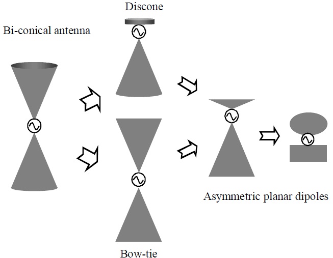
Alternatively, planar monopoles (dipoles) or disc antennas with broad bandwidths and small size have long been proposed for UWB applications [16-19]. The earliest planar dipole may be the Brown-Woodward bowtie antenna, which is a simple and planar version of a conical antenna [18].
Fig. 1 shows the evolution of three-dimensional frequency- independent conical antennas to small planar antennas as an example.
The three-dimensional bi-discone design features the frequency-independent impedance matching and radiation performance across a wide operating bandwidth but suffers its big volume. Bow-tie and discone dipole-type designs have greatly reduced the volume compared to original bi-conical dipoles but still too large to apply in portable/mobile UWB devices. The asymmetrical planar designs with further size-reduction have been the best options for UWB devices [16-51]. However, the price paid for the great reduction of the overall dimensions of the antenna is the significant degradation of radiation performance such as gain and radiation direction with the operating frequency. On the other hand, such designs may be good for portable devices where random omni-directional coverage is desired.
In this paper, we will mainly focus on reviewing the development of planar UWB antennas. The next section will brief the important milestones of planar UWB antenna designs. Then, a variety of planar UWB antennas invented for broadband operation, miniaturization, and multiple functions are introduced. At last, the comments on the development of UWB antennas in future are provided.
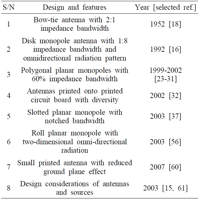
[Table 1.] The summary of important planar antenna designs

The summary of important planar antenna designs
Ⅱ. Key Milestones of Planar UWB Antenna Design
Due to the specific applications of UWB systems, the planar versions of designs have attracted much attention in research and development of UWB antennas. Here, we reviewed the important milestones of the broadband technology in UWB antennas by summering the pioneering designs in Table 1.
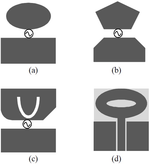
The bow-tie antenna is the planar version of a bi-conical dipole antenna with greatly reduced volume as shown in Fig. 2(a) and (b) [20]. The disc and polygonal planar monopole or dipole antennas are the variations of thick monopole or dipole or bow-tie antennas, which maximum dimensions determine their low-edge operating frequencies and the feed-gaps formed by edges of upper and bottom radiators or ground plane determine the impedance matching [18-51]. The designs have the same features as a dipole but UWB impedance bandwidths.
The slotted planar monopole features the notched bandwidth by introducing an additional anti-resonance where the additional current around the slot edge is excited with almost the same amplitude as the original radiating current on the monopole but the out-of-phase at certain designed frequencies as shown in Fig. 2(c) [37]. With the notched band usually allocated in the WiFi bands of 5-6 GHz, the possibility of interference between UWB and WiFi devices will be reduced. The design challenges of such antennas include how to achieve sharp and wideband stopband filtering performance without the introduction of any additional elements in the antenna design.
To keep an antenna small in size and low in cost, we can fully integrate the UWB antennas with circuits by printing the antennas onto the printed circuit board (PCB) like any printed circuits there as shown in Fig. 2(d) [32,50]. A planar UWB antenna etched onto the dielectric substrate of the PCBs basically consists of one upper radiator and one ground plane which may be co-planar or under the dielectric substrate. The radiators can be fed by a microstrip line or coaxial cable. Currently, majority of the UWB antennas are related to the printed PCB ones.
Besides the small planar antennas mentioned above, there have been modified planar antennas for specific requirements such as directional, bi-directional, and twodimensional omni-directional radiation. As known, thick or modified cylindrical monopoles or dipoles can provide broadband impedance matching and omni-directional radiation characteristics but usually with big volume [52-55]. On the other hand, the planar antennas can achieve broad impedance bandwidths but omni-directional at all operating frequencies due to structurally rotational asymmetry. Therefore, a roll monopole was presented to improve the radiation performance of a planar monopole across a broad bandwidth [21,56-58]. Basically, the roll monopole is constructed by twisting the planar radiator to a roll shape.
The impedance and radiation performance of a printed PCB antenna will be affected by the ground plane which usually is part of circuit board. The changes in the shapes and size of the ground plane will cause the difficulty in antenna design and measurement. The ground plane effects become much severer when the size of the ground plane is reduced. This has been one of the most challenging design issues in small antennas [59]. The proposed notched small printed UWB antenna achieved a great reduction of the effects caused by the changes in ground plane [60]. Such a concept has been applied in the designs with miniaturized size, diversity performance, and filtering functions which will be elaborated in the next section.
In addition, it should be mentioned that the unique design considerations for antennas and source pulses in UWB wireless communication systems were first presented in 2003, which differentiated the existing UWB antenna design from the conventional ones from a system point of view [15,61]. The suggestions of design considerations have significantly affected the later designs.
There have been many nice designs published in literatures. Majority of the designs have addressed only general design challenges such as achievable impedance bandwidth. However, besides the impedance matching bandwidth there are many specific design requirements in particular applications, such as gain, beamwidth, radiation direction, polarization, and so on. Next, four types of UWB antenna designs with special considerations are exemplified.
1. Small Ground-Independent UWB Antennas
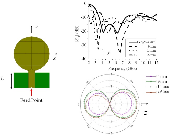
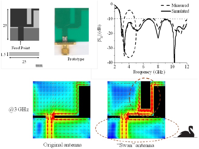
The planar UWB antennas can provide the key features of small size, broad bandwidth, low cost, and integrated solution. However, the “ground plane” of a printed antenna suffers from the severe effects of changing the size and shape of the ground plane on the performance of the antennas. For instance, consider a UWB antenna printed on a 1.5-mm thick RO4003 (Rogers Corp., Roger, CT, USA) substrate as shown in Fig. 3. The antenna comprises of one upper circular radiator, one rectangular ground plane printed on the other surface, and one 50-Ω feeding strip connected to the botom edge of the circular radiator. The feeding strip is fed at its bottom end. The gap between the bottom of circular radiator and upper edge of ground plane is set 1 mm. The length and width of the ground plane, respectively, are
This design is able to achieve good impedance matching across the entire UWB bandwidth of 3-10.6 GHz when
One solution to suppress the unwanted effect of the ground plane was presented [60] as shown in Fig. 4. Notching the upper radiator reduces the first resonant frequency by 30% as compared to the original one due to the increase in the effective current path on the radiator. Then, the antenna with notches was optimized to cover the entire UWB band of 3.1-10.6 GHz. The antenna prototype was connected to a RF coaxial cable via a RF connector in the measurement. The excellent agreement between the measured and simulated |
Comparing the current distributions on the antennas with and without the notch, it is found that the current around the notch becomes much stronger than that without the notch as shown in Fig. 4. This implies that majority of the radiation of the notched antenna is from the portion around the notch. As a result, concentrating most of the current around the notch reduces the effect of the changed ground plane so that a ground plane independent, small-sized UWB antenna was achieved with a “Swan” shape.
2. Small Diversity UWB Antennas
The UWB systems are usually used in dense indoor environments with rich reflection. Like all other wireless communication systems, the multipath of RF signal propagation degrades the quality of a link. Therefore, multiple antennas are often used to achieve diversity for enhancing the reliability and robustness of indoor wireless connections. However, due to the very limited space for installing at least two or more antennas inside a portable device, it is very difficult to achieve the sufficient isolation between the antennas, which is one of the most important figure-of-merit to assess the diversity performance. Therefore, this poses a design challenge for UWB antenna designers [32].
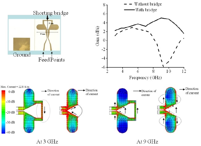
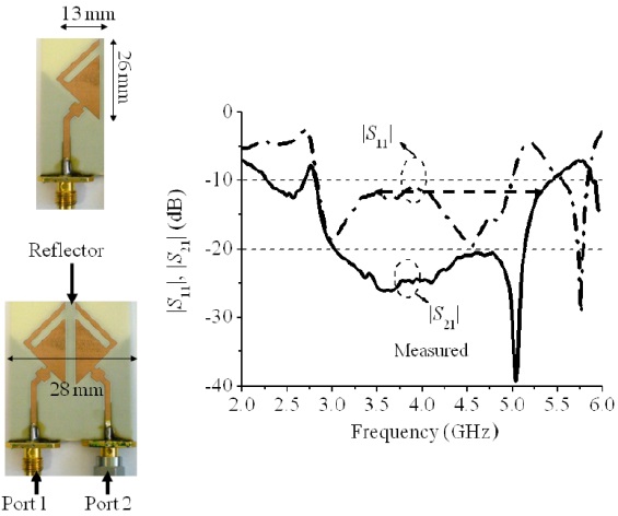
To alleviate the challenges mentioned above, the proposed “Swan” antenna was further slimed to form the diversity antenna as shown in Fig. 5, where the two elements are positioned face-to-face with a narrow strip etched on the opposite surface between the elements as a reflector [62]. This antenna is capable of achieving the impedance matching and 20-dB isolation across the lower UWB band of 3.1-5 GHz so that the actual diversity gain reaches 9 dB with high antenna efficiency, which includes the loss caused by impedance mismatching.
Due to the very wide operating bandwidth, the outof- band interference between UWB devices and other surrounding electronic devices occurs possibly in the dense environments. For example, there have been many wireless applications such as WiFi operating in 5-GHz bands. To avoid the possible interference between the UWB systems and WiFi 5 GHz systems, the usage of UWB systems in the 5 GHz band (4.9-5.9 GHz) is avoided. Furthermore, the suppression of the signals outside the operating bands, for instance, lower than 3.1 GHz and higher than 4.8 GHz is helpful in UWB system design.
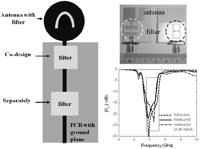
Usually, we can integrate the filtering functions of bandpass or bandstop into the UWB antennas in at least three ways as shown in Fig. 6. It is easy to apply the filters in the circuits and implement them separately. The separately designed and inserted filters need additional space and components which may increase the overall size of RF section. Alternatively, the filter can be integrated with the antenna by applying it right below the upper radiator of antenna and sharing a common ground plane with the antenna for size reduction. Due to the sharing of the ground plane, the interaction between the filter and antenna is inevitable. The co-design of the filter with high Q-factor and the antenna with low Q-factor is necessary as shown in Fig. 7.
In addition to the separately designed and co-designed filters, the filters can be embedded into the upper radiator as part of the radiator as well. By notching the upper radiator, the stopband appears without any increase in size and change in the radiation performance. However, the challenges of such designs include:
1) The radiator operates at a low Q-factor mode for high radiation capability but the filter at a high Qfactor mode to suppress any leaky loss (namely radiation).
2) Low Q-factor design can achieve broadband performance but the high Q-factor of filter makes the filter narrowband.
3) Due to limited Q-factor, it is difficult for the filter to realize sharp rejection skirts and deep rejection [37,63,64].
4. Directional UWB Dipole Antennas
The specific requirements of UWB antennas stem from particular applications as mentioned above. For example, one UWB pint-to-point link needs the dipole/ differential-type of UWB antenna with the acceptable gain of larger than 2 dBi at a fixed direction over the whole UWB band of 3.1-10.6 GHz. The fat dipole can achieve the impedance matching across the whole UWB band but the gain varies up to 8 dB at the boresight over the operating bandwidth. A shorting bridge was introduced between the two arms of the dipole to form a “Kite” for stabilizing the gain as shown in Fig. 7 [65]. From the comparison of current distributions on the antennas with and without the shorting bridge, it is found that at the lower frequencies, the “Kite” antenna operates as a fat dipole but a loop antenna at higher frequencies so that the radiation along the boresight is consistently high enough.
Besides, the UWB antennas may be required to fit other specific requirements in some applications. For instance, one UWB-based mono-station localization system needs a six-element array to horizontally cover a 360° range where each element must have an unchanged beamwidth of 60±5° across the lower UWB band of 3.1 -4.8 GHz. A big aperture bi-directional UWB antenna element was proposed with an optimized reflector for achieving the required accuracy of the localization [66].
Due to the uniqueness of UWB technology and applications, planar antennas and their variations have demonstrated their attractive merits of broad bandwidths, stable phase response, easy fabrication and integration with other RF circuits, small size, light weight, and embeddable configuration. Therefore, much effort has been paid to developing the planar UWB antennas. The development of the planar UWB antenna technology have not only contributed to UWB applications but also spurred the fast progress in broadband technology of miniaturized antennas.
In future, the research into UWB antennas will still be one of hot topics in academia due to their unique design challenges: