The realization of media having negative permittivity and permeability, so called left-handed metamaterial, became feasible after 1991 when Pendry et al. [1] proposed a new method that used an array of thin wires and split ring resonators (SRRs). A number of approaches followed in many aspects in an effort to realize similar left-handed characteristics [2-5]. However, most of these showed high losses and narrow operating bandwidth (having a very sharp slope near the resonant frequency). In fact, the problem of SRRs has seldom been approached seriously from an engineering viewpoint, although many trials have been made. Basically, SRRs are similar to the ring resonator in their characteristics. In this paper, we model the ring resonator (SRRs) starting from the definition of a magnetic dipole moment and leading to a useful equivalent circuit. The mechanism of SRRs is explained with more familiar terms than in [1]. In addition, we provide a method of realizing the negative permeability over a large bandwidth. It is believed that the presented modeling will provide significant convenience and flexibility for the realization of the left-handed materials.
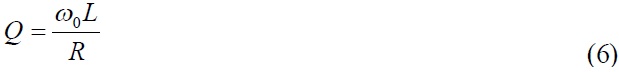
Ⅱ. Novel Modeling of a Ring Resonator (SRRs)
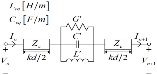
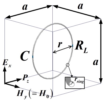
We have modeled the ring resonator using an equivalent circuit. The dimensions of the ring resonator and its orientation with respect to the given transverse electromagnetic (TEM) wave are depicted in Fig. 1. The wave travels in the z-direction with the electric and magnetic fields oriented in the x- and y-directions, respectively. The radius of the loop is

where
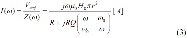
Accordingly, the current
The magnetization
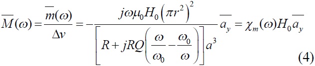
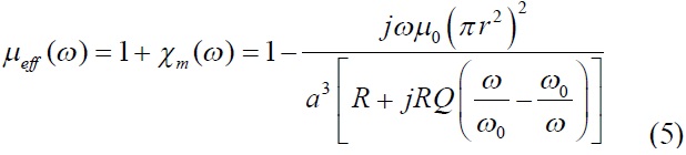
where

is magnetic dipole moment
The parameter

For an instance,
where
The value of parameters
Ⅲ. Simulation Results and Discussion
The ring resonator used in the electromagnetic (EM) simulation is made of copper and is designed at 13.56 MHz. The unit cell size (
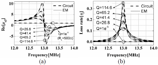
Fig. 5(b) shows the loss rate of the ring resonator with different values of

Each case shows that the highest loss rate is shown at the resonant frequency, but loss rates are very low at the operating frequency of 13.56 MHz (
Comparison of Figs. 4(a) and 5(a) shows that the resonance occurs less sensitively as the value of
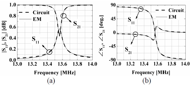
The effective permeability of a ring resonator (or SRR) has been formulated based on the concept of magnetization. Its equivalent circuit has also been proposed and analyzed with necessary comparisons. The circuit and EM simulated results are in excellent agreement. The drawback of the narrow-banded SRRs can be significantly ameliorated based on the proposed modeling and formulations. With this modeling, the problem of synthesizing the effective medium can be engineered more systematically.


, (b) Loss rate, ηl (varing RL from 0.15 to 500 Ω).](http://oak.go.kr/repository/journal/12420/E1ELAT_2013_v13n2_134_f005.jpg)