The electromagnetic band gap (EBG) properties of passive metallodielectric periodic structures have recently been investigated, metallic arrays printed on a dielectric substrate or connected to the ground plane through via holes have been presented as artificial magnetic conductors (AMCs) [1]. New types of ground planes utilizing an AMC structure, which has a high impedance surface (HIS), have led to significant advancements in many applications. AMCs have an unusual boundary condition and consequently can be used as a new type of ground plane. The design of new ground planes is an active area of research for replacing perfect electric conductors for antennas or microwave applications due to their back radiation shield and gain enhancement [2-5].
One of the general performances of the AMC structure is that the reflection phase decreases from +180° to ―180° with the resonant frequency at the center; therefore, the resonant frequency should be determined at 0°. In addition, AMCs usually reduce the antenna’s profile to about
In this paper, we present the design and analysis of a reflector, which consists of periodically arrayed AMC structures, and compare this reflector to conventional models. The aimed frequency band is 2.4 GHz. Other investigators have used various methods to verify proposed AMC structures [6,7]. However, direct analysis of the characteristics of AMC structures is difficult because AMC structures are one of the methods to embody the metamaterial characteristic. Therefore, AMC structures are generally being applied as absorbers [8], filters [9], reflectors [10], spacers [11], or secondary devices for improving the performance of antennas [12], and their characteristics of transmission or reflection are being analyzed by simulation or measurement.
A dipole antenna with the periodically arrayed AMC reflector can work perfectly at a tenth of the wavelength without affecting its performance; whereas, a perfect electric conductor (PEC) reflector does not show any performance at the same distance due to reverse image currents that reduce radiation efficiency (because of being out-of-phase) [12-16]. The AMC reflector has two important characteristics: behavior as a perfect magnetic conductor (the parallel image currents are in-phase) and the ability to control electromagnetic wave propagation at the resonant frequency. Therefore, the structure can obtain efficient radiation close to the antennas and eliminate multipath interference [2].
The surface of the periodically arrayed AMC cells printed on a grounded dielectric slab has extremely high impedance. This high-impedance surface is easily fabricated by using the printed circuit board technique. Sievenpiper [3] proposed a simple laminating structure using a metallic via hole. Normally, the mushroom-like surface structures have via holes, making the design and fabrication complicated.
The simplest design is a two-layered structure without the metallic via hole. However, an HIS without via holes provides a narrow bandwidth of about 4% or 5% because HIS without via holes represent only a small perturbation of the flat metal surface. When the metallic patch and the conducted ground plane are connected by the metallic via hole, the equivalent circuit is composed of inductance and capacitance. The high impedance is then generated on the surface of the metallic patch. The capacitance originates from the fringing electric fields between adjacent patches, but the inductance is determined by the thickness of the substrate. Therefore, we can control the high impedance surface by the thickness, relative permittivity, and size of the patch. Hence, a metallic via hole in the conventional AMC structure connects the designed patch to the ground plane, and sometimes a via hole can be removed.
In this paper, we present a novel AMC structure that has a mushroom-like surface without a via hole. We used a simulation to analyze the designed AMC structure. In order to verify our proposed AMC structure, the dipole antenna above the designed AMC structure (as a reflector) was analyzed by measurement. We also applied the reflector to a mobile phone for reducing the SAR value. In Section Ⅱ, the designed AMC structure and the characteristics are presented. The proposed AMC is compared to conventional structures, and simulation experiments are used to identify the optimized parameters. In Section Ⅲ, we present the measurement experiments to verify performance, and this is followed by our conclusions in Section Ⅳ.
Ⅱ. Design and Characteristics of AMCs
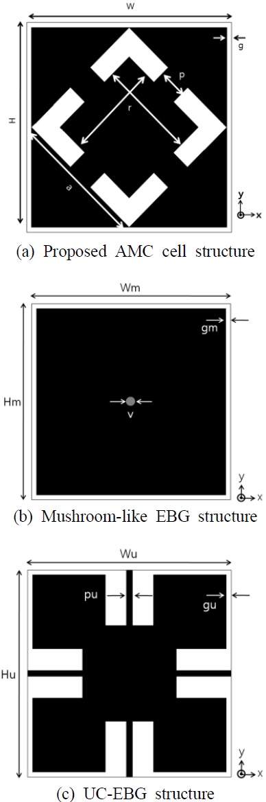
The structures shown in Fig. 1 have high impedance and operate at a frequency of 2.4 GHz. The proposed AMC structure was compared to a conventional mushroom- like EBG and a uniplanar compact EBG (UCEBG) structures presented in [3] and [5], respectively; their geometries are shown in Fig. 1(a)-(c).
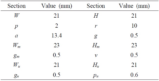
[Table 1.] Dimensions of the patches

Dimensions of the patches
The unit cells were printed on a 2.6-mm thick FR4- PCB (relative permittivity=4.6, loss tangent=0.02). The cell dimensions of the three different patches are presented in Table 1.
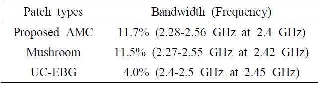
The bandwidth of AMC structures is normally decided by the range of the reflection phase changes from +90° to ―90°. Fig. 1(a) shows the proposed EBG structure with a bandwidth of 11.7% (2.28-2.56 GHz at 2.4 GHz). Fig. 1(b) shows a conventional EBG structure, which has a bandwidth of 11.5% (2.27-2.55 GHz at 2.42 GHz). Fig. 1(c) shows the UC-EBG, which has a bandwidth of 4.0% (2.4-2.5 GHz at 2.45 GHz). The designed AMC has a bandwidth that is about three times wider than the conventional UC-EBG.
For our proposed structure to have a wider bandwidth, the substrate’s thickness is controlled or slots on the metallic patch are symmetrically added. Capacitance is generated by the slots; therefore, we designed the slots on the patch for controlling the capacitance and reactance. Finally, we controlled the resonant frequency and the bandwidth. The calculated bandwidths of each AMC structure are shown in Table 2.
Using a simulation tool with the FDTD method, we designed all of the structures to contain the in-phase reflection on their surfaces for their normal incident planes at 2.4 GHz [17]. For obtaining the desired resonant frequency, the calculated AMC cell size should be about 0.16
[Table 2.] Calculated bandwidth by patch type
Calculated bandwidth by patch type
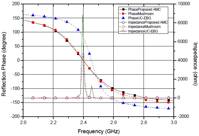
The reflection phase determines the frequency range. Fig. 2 shows the simulated reflection phases of the designed AMC, the mushroom-like surface employing the via hole, and the UC-EBG. For a frequency of 2.4 GHz, all the surfaces have an in-phase reflection. When the patches are connected to other patches, i.e., the AMC surface becomes a planar type, the 0° reflection phases move to higher frequency bands. Otherwise, the frequency band will have a small and short period.
In the case of the via hole, there is a negligible difference between the presence and absence of the via hole in the proposed models because of extremely high wave impedance, as shown in Fig. 2. Although the performances with and without the via hole are almost the same, the fabrication of a surface without the via hole is easier and cheaper. Therefore, the proposed AMC structure has several advantages: broad bandwidth, short reflecting distance, small size, simple structure, low price, and easy fabrication. In addition, each slot in the structure plays a key role in tuning the desired frequencies. Resonant frequencies from 2 GHz to 3 GHz can be controlled by the length or width of the slots.
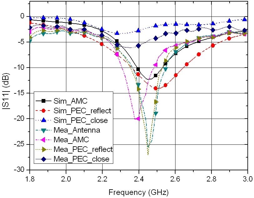
A basic dipole antenna (smaller than a quarter of the wavelength) close to a conventional metallic reflector has very poo r performance. The image currents appear out-of-phase rather than in-phase so that the radiation in the antenna is cancelled by the currents. However, performance is greatly improved when the AMC surface is used as the reflector. In order to verify this, we simulated and measured the reflection coefficients of dipole antennas placed above PEC and AMC reflectors. We calculated the length of the dipole antenna to be about 62.5 mm at 2.4 GHz. A vector network analyzer (HP8510c) was used for the measurement of the reflection coefficient in the laboratory.
We determined the numerical formulas for our calculations as follows. The reflection coefficient can be calculated if a normally incident plane wave that scatters from a semi-infinite dielectric-magnetic slab of a certain depth in free-space is considered. When the permittivity and permeability are
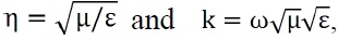
respectively. In free-space the parameters are

respectively. The relative permittivity and permeability are then derived by the expressions ε = ε0εr and μ = μ0μr, respectively. The reflection and transmission coefficient values were derived previously [16]. Usually, the reflection (
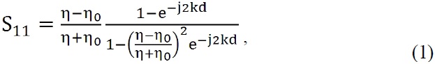
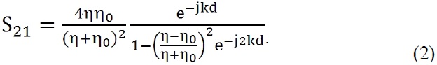
Metamaterials have been shown to exhibit very large wave impedances so the corresponding impedance will approach infinity. The reflection and transmission coefficient values from (1) and (2) therefore become


We used a slab with a large impedance for the AMC reflector, which has a broad bandwidth and in-phase reflection. Although the permeability is not extremely large and the permittivity is near zero, the impedance can be made to be extremely large, making the reflected index
small and giving the proposed AMC these characteristics.
The measured reflection coefficient results of the antenna based on the reflector are shown in Fig. 4. Mea_ antenna denotes reflection without a reflector in free space. When the antenna and the PEC reflector are placed close together (PEC_close), there is no reflection. If the wavelength of the driving source in free-space is
The results shown in Fig. 4 were measured by using the network analyzer in the laboratory. The distance between the reflector and the antenna should be fixed at a tenth of the wavelength (12.5 mm), but it is not enough to control the gap between the reflector and the antenna and to fix the antenna above the reflector in the laboratory environment. Therefore, we analyzed the shift in the resonant frequency. For further study, we will study the method to eliminate the error.
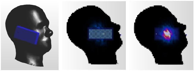
Fig. 5 shows the head of the phantom model and SAR distributions.
For analyzing the effect to humans, the reflector was applied to the SAR analysis. The reflector could decrease the back radiation of the antenna toward the human phantom, but there was still radiation leakage because of the reflector size. As shown in Fig. 5, a small quantity of back radiation reached the human phantom. Therefore, we can expect the SAR values to be extremely reduced with the reflector compared to without the reflector. In this simulation, the reflector size was 84 mm×126 mm for the tablet PC and 42 mm×84 mm for the mobile phone. The interval between the phantom and the antenna was about 16 mm. The dipole antenna was located in the middle of the mobile device, and the mobile device was attached to the ear reference point.
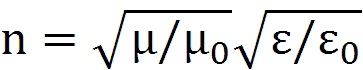
[Table 3.] Comparison of the peak SARs (1g averaged)
Comparison of the peak SARs (1g averaged)
The calculated peak SAR averaged over 1 g was only 0.002 W/kg when the input power was 1 W and the distance between the human phantom and the device was 20 cm. The results show that over 98% of the SAR was blocked compared with no AMC reflector. For analyzing the worst case, the operating power input was 12.8 W and the SAR was 1.6 W/kg without the reflector at 20 cm distance. However, the SAR was only 0.078 W/kg when the reflector was inserted in the device. The calculated peak SAR was only 0.262 W/kg when the reflector was inserted in the mobile phone and installed at the ear reference point; almost 95% was blocked by the reflector. The peak SAR was found at the center of the ear without the reflector and the junction of the earlobe and the jaw with the reflector.
This is an expected result, and the normal PEC reflectors have the same effect. However, the normal PEC reflector must be placed at a quarter of the wavelength from the antenna to be in-phase. In our model, the reflector can be moved close to the antenna (a tenth of the wavelength) for the same performance. Hence, the proposed reflector can be inserted in mobile devices. The analyzed SAR results are shown in Table 3.
We designed a novel AMC structure to be a reflector. From the simulated and measured results of the reflection phase, the designed structure performed at 2.4 GHz with an 11.7% bandwidth. The proposed AMC structure has several advantages: broad bandwidth, short reflecting distance, small size, simple structure, and inexpensive and easy fabrication due to the absence of a via hole. For the simulated and measured tests of the reflection coefficient, both the dipole antenna and the proposed reflector were located close together (about 12 mm); the antenna operated identically to the PEC reflector at a quarter of the wavelength. Therefore, this reflector can be used to decrease the size of systems employing a reflector.
The effect on humans was analyzed by inserting the designed reflector into a tablet PC that faced a human body. The calculated peak SAR averaged over 1 g was 0.125 W/kg when the input power was 1 W. For analyzing a worse case scenario, an input power of 12.8 W and a maximum reference level of 1.6 W/kg at a distance of 20 cm from the human phantom resulted in a peak SAR of only 0.078 W/kg. In addition, 94.7% of the calculated peak SAR was blocked by the reflector when it was applied to a mobile phone. The designed reflector should, therefore, block electromagnetic waves reaching a human body.