To meet today’s transport requirements multi-hull vessels are increasingly required to travel faster, with increased operability and passenger comfort. Although this requirement is transparent, the solution is not so simple, due to the level of design compromises involved. Significant levels of research have focused on complex ‘hybrid’ type hull forms that require specific mission profiles. However, there is little research targeted at both novel and fundamental technological solutions that will enable further reductions in vessel motions at higher service speeds.
Catamaran hull forms inherently suffer from relatively poor seakeeping performances unless they are designed as a SWATH or similar form, which has its own restrictions associated with speed and draft as well as the load carrying capability. Within this context, it would be only natural to combine the superior seakeeping performance of a displacement type Deep-V mono hull with an efficient catamaran hull form to improve the poor seakeeping performance of catamarans thereby reduce their speed loss in a seaway. This hybridisation of two hullforms has been proposed for the first time at Newcastle University by Atlar (1997) and developed through successive projects (Atlar et al., 1998; Atlar et al., 2009) and a recent PhD research, all of which resulted in the first systematic Deep-V catamaran (UNEW-DVC) series including limited model tests supporting the series development by Mantouvalos et al. (2009). The main features of the UNEW-DVC series are that the demi hulls are symmetric with large deadrise angles that are constant after midship, and that the bow sections have Serter’s trademark antislamming bow feature (Serter, 1989). The after body of the UNEW-DVC series hull forms finishes with a transom that has an equivalent area to the mid-ship cross sectional area. The favourable effects of the anti-slamming bow feature of two equivalent displacement of passenger ferry catamarans, one of which was based on the UNEW-DVC series while the other was an existing round bilge catamaran with wave piercing bow, were demonstrated by the comparative vertical motion responses, slamming and added wave resistance characteristics in Atlar et al. (2009).
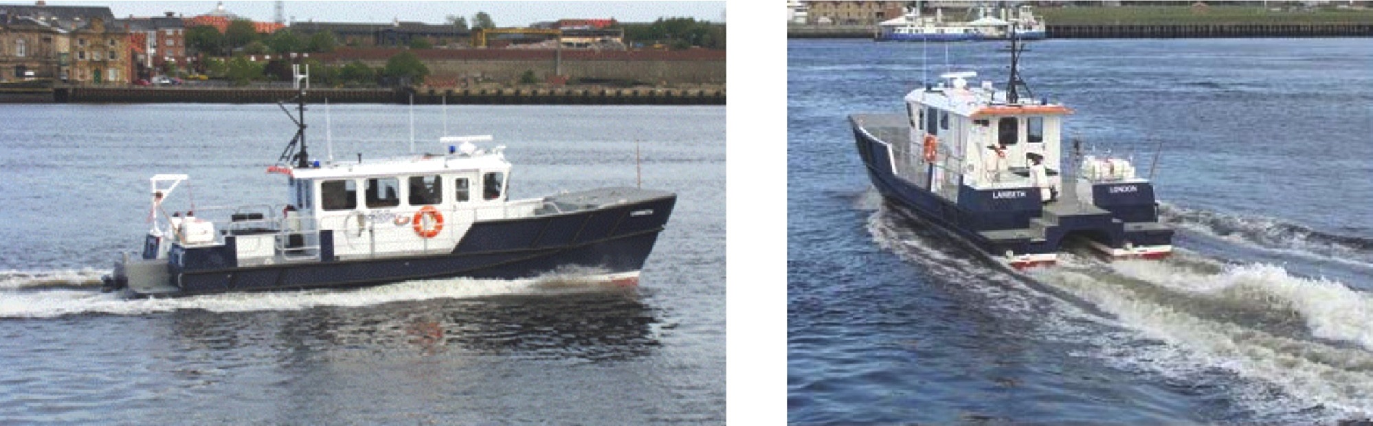
The first building application of the UNEW-DVC series was a 14
In order to improve the hydrodynamic performance of the DVC catamaran based on the experience with the m/v Lambeth, a novel bow configuration, known as an “Anti-Slamming Bulbous Bow”, was applied to the DVC design to improve both the wave making resistance and slamming characteristics. The anti-slamming bulbous bow also gave the DVC hull form increased damping in the vertical plane and hence improved the vertical motions and accelerations in waves, something absent from most catamaran designs.
Whilst the PLA design showed improved wave resistance and seakeeping by modifying the bow, the design optimisation also included the stern, another problematic area for catamarans. The PLA design was intended for river duty, often in shallow reaches of the River Thames, which enforced limitations on the draft and hence size of the propeller available for the vessel. With no modification to the hull, this would result in selecting a propeller diameter that was considerably less than the optimal value in order to meet the design clearance requirements. It was therefore decided to adopt a tunnel stern (also known as propeller pocket) to allow a larger diameter propeller, to reduce the shaft inclination and to decrease navigational draft. The concept of a stern tunnel has been successfully used to allow the use of a larger diameter propeller and allows lower shaft inclination angles, typically on inland waterway vessels, e.g. Mitchell (1953) and Bogdanov et al. (1974). The design of the tunnel stern is always a matter of trade-off between the propeller efficiency gain and the tunnel losses from poor tunnel flow conditions. Bogdanov et al. (1974) provided some recommended values for the geometry of a tunnel stern for inland waterways and aspects of these were incorporated into the design. In a relatively recent practical study, Blount (1997) provided a summary of the advantages and disadvantages of using propeller tunnels in high-speed craft design.
In order to take full advantage of the anti-slamming bulbous bow and tunnel stern for the further design refinement of a Deep-V catamaran the design of the Newcastle University’s new research vessel, “The Princess Royal” took much design guidance from the PLA 14
SPECIFICATIONS OF NEW DEEP-V CATAMARAN
Based on the useful findings from the design experience with the PLA catamaran, a parametric study was conducted by Sampson and Atlar (2009) to determine the initial size and hull form geometry of a new catamaran (The Princess Royal) for Newcastle University. By taking 18
[Table 1] Specification of catamaran.
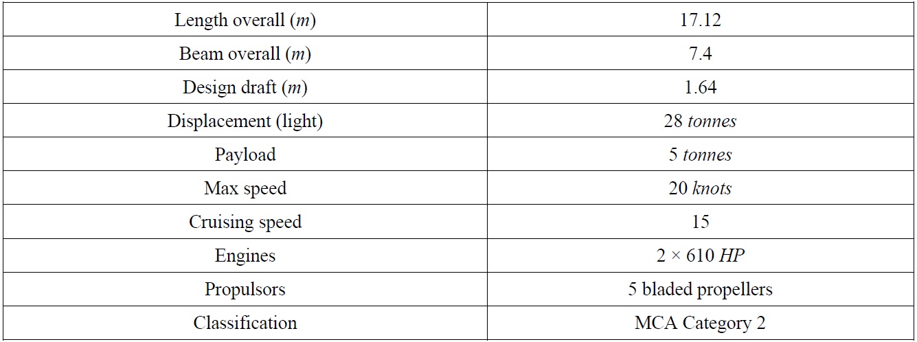
Specification of catamaran.
The preliminary analysis with the potential flow code (SHIPFLOW) indicated that the propeller driven alternatives required less effective power for the same speed as well as displaying reduced wave making resistance compared to the waterjet driven alternatives. The final decision between the four candidate designs was for the propeller driven UNEW-DVC hull form. This design was selected for further optimisation on the basis of power saving and suitability and flexibility to serve as a research vessel. The further details of this preliminary hullform selection can be found in Atlar et al. (2010).
FURTHER HULLFORM DEVELOPMENT OF NEW DEEP-V CATAMARAN
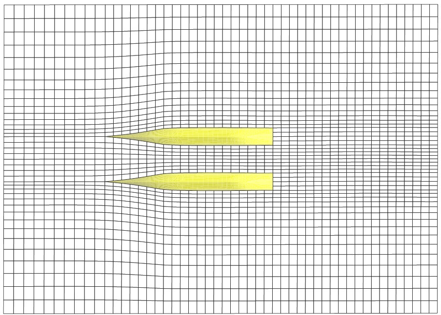
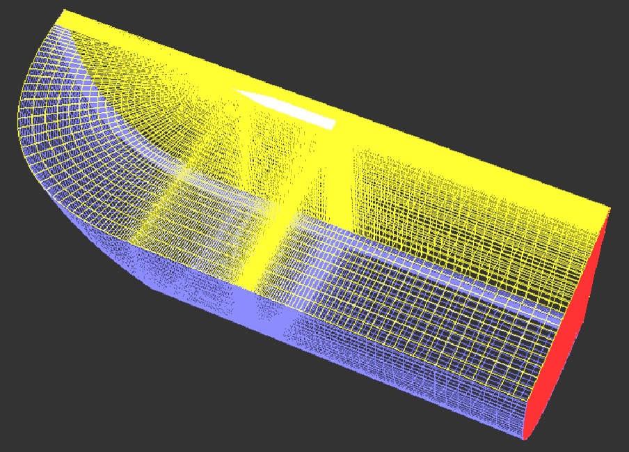
Having determined the preliminary dimensions and basic hull lines for the research vessel, the next step was to optimise the hull lines within a reasonable envelope of the preliminary dimensions (Atlar et al., 2010). In order to improve the wave-making resistance component, which is dominated by the fore body, the anti-slamming bulbous bow was investigated using the SHIPFLOW potential solver. The SHIPFLOW code used a three-dimensional panel method that distributed a large number of panels both over the hull and on the adjacent free surface. Fig. 3 shows the quadrilateral structural patches that are distributed on both the hull and the free surface. Around 1500 panels were used over the hull and on the free surface for this purpose. To understand the complex viscous flows around the after body of the design, the use of a sophisticated computational fluid dynamic (CFD) method is critical. For this study, the steady and double body flow field model was employed to calculate the viscous pressure resistance and wake flow into the propeller plane using FLUENT 6.3. The realisable k-ε turbulence model, with nearwall function to describe the velocity profile near the wall, was used for the turbulent flow. Iterative numerical solutions were considered to be sufficiently converged when the normalized residuals of all the variables were lower than 1×10⁻⁴. Fig. 4 shows the half of the entire computation domain that extends 1.6 model lengths upstream, 2.5 model lengths downstream and 1.5 model lengths sideway. The domain took into account the vertical plane of symmetry consideration. For the numerical solution of the governing equations the domain was discretized in the 1,500,105 cells, in which the unknown variables were found. The boundary conditions were imposed in the solution method as follows: a velocity inlet boundary condition (equal to the model velocity) was used in the inlet whilst a pressure outlet boundary condition in the outlet. No-slip conditions are imposed on the wetted part of the hull surface, which means that all of the velocity components on the surface are zero, whilst a symmetry boundary condition was used in the remaining regions.
>
Development of the fore body
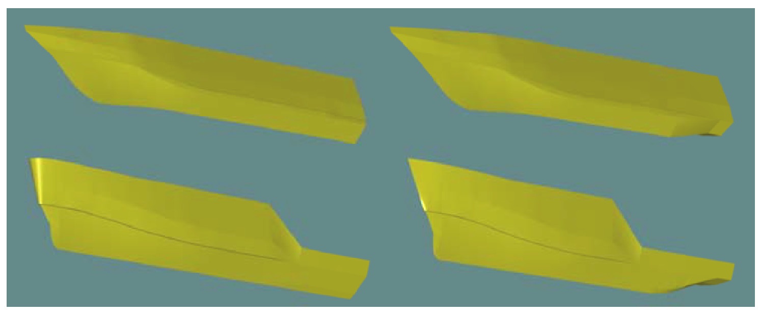
It is a well-known fact that the anti-slamming bow with a droop feature results in a deeper draught at the bow, However, when compared to a conventional bow without such a droop the anti-slamming bow will keep the vessel’s forefoot in contact with the free surface of the water as much as possible,. According to Serter (1993), who pioneered the anti-slamming bow concept, this would not only reduce the slamming frequency of the vessel but it will also reduce the wave-making by maintaining the actual waterline length of the vessel, hence smaller Froude number, underway as much as possible. While Serter’s “Antislamming bow” feature was attractive for the seakeeping and wave-making already, it was decided to combine the antislamming bow with an optimised bulb to improve the resistance and vertical motion characteristics of the design still further. This novel bow configuration, that can be named as “Anti Slamming Bulb”, will not only improve the wave-making in a conventional way by reducing the bow waves but it will also provide the hull form with increased damping in the vertical plane and hence to improve the vertical motions / accelerations in waves.
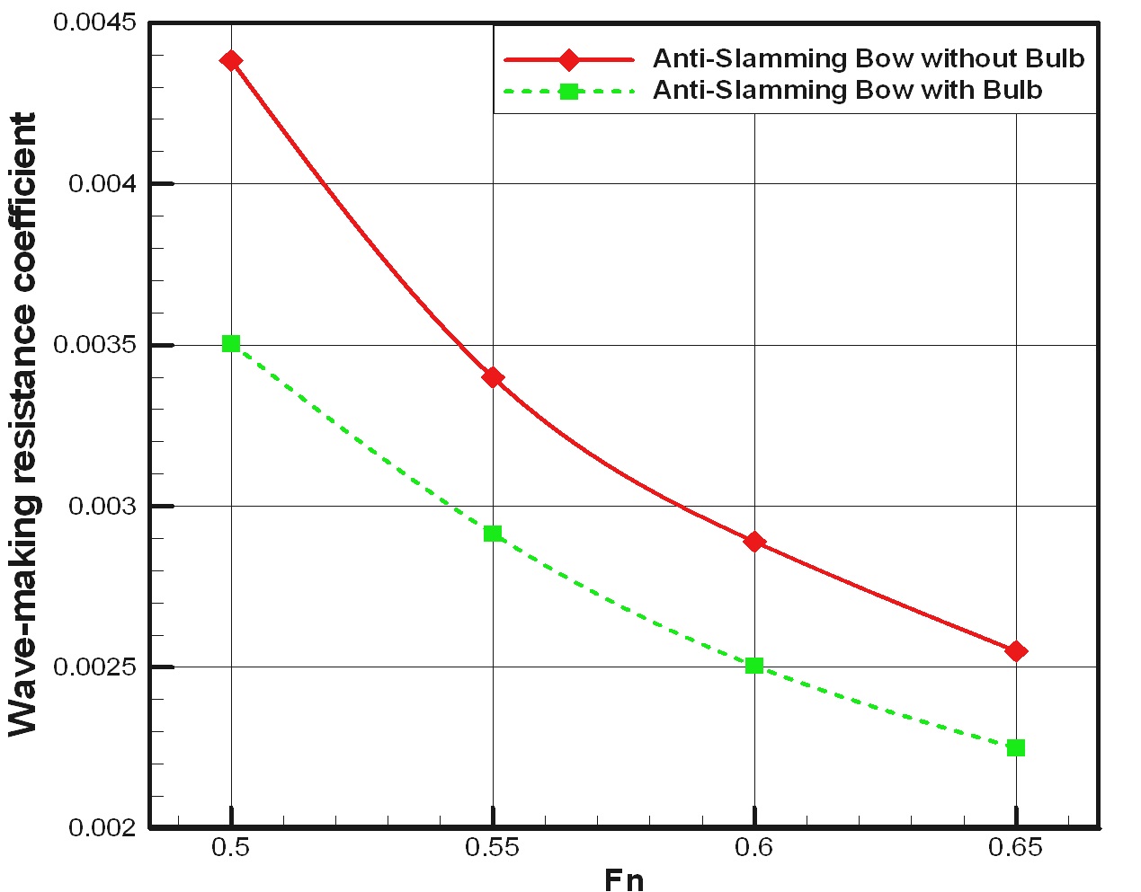
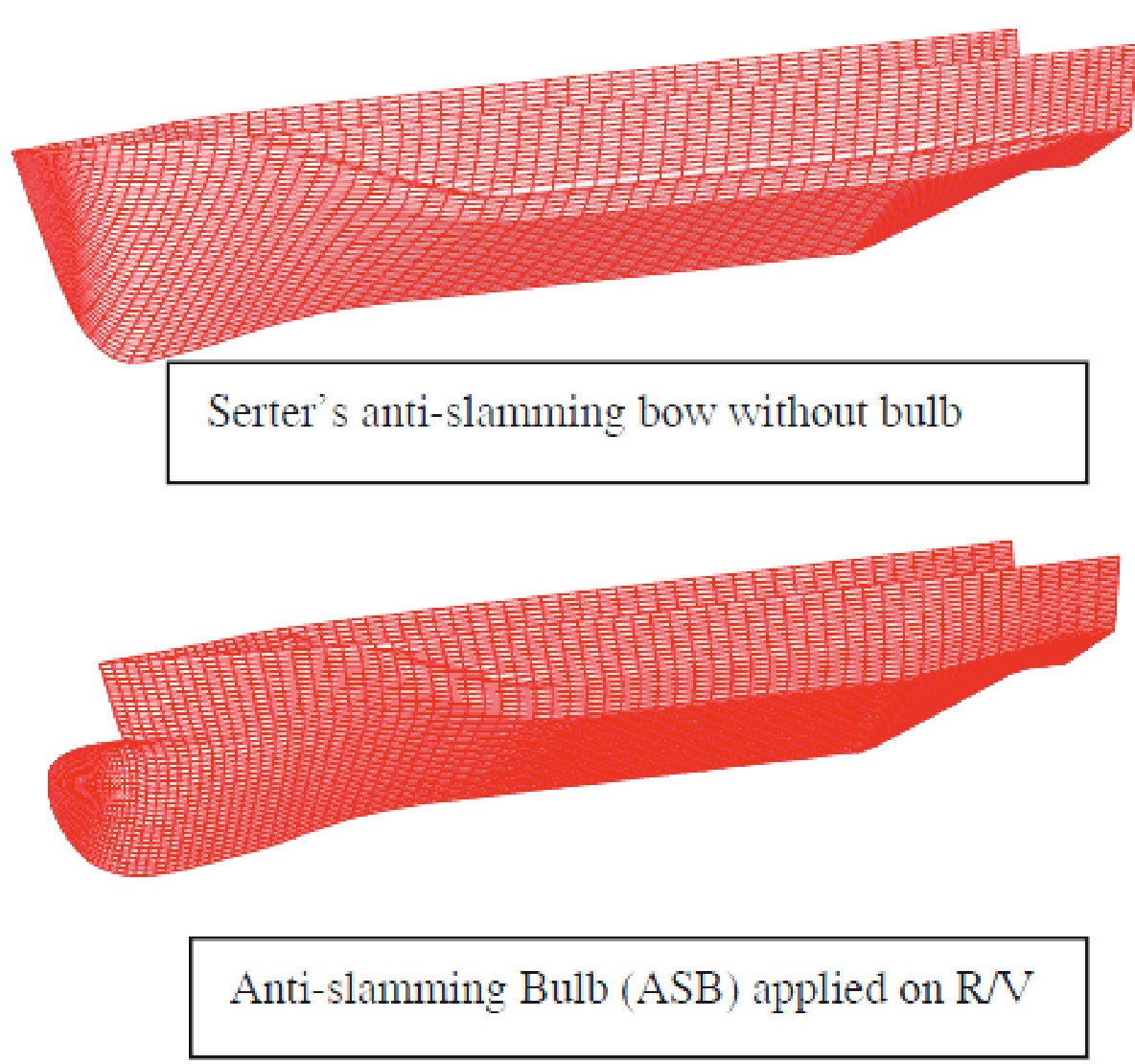
The optimisation of the forebody with the introduction of the anti-slamming bulb was conducted by the approach given by Danisman et al. (2001) and Danisman and Atlar (2002) where the objective function was chosen as the total resistance, which was assumed to be the sum of frictional drag and wave-making resistance. The frictional drag was formulated by the ITTC-57 model-ship correlation line while the wave making component was obtained using the Michell integral, the latter being a linear formulation of the ship wave resistance expression based on the thin ship theory. In both formulations the ship’s hull was represented by using “tent functions” for the sake of iterative computations and rapid surface representations, this was then combined with the quadratic programming technique to search for the optimum. Once the optimal form was obtained, the performance analysis was conducted by a potential flow based panel code (SHIPFLOW) with a linear approach. The linear approach would not give an accurate result compared to non-linear prediction but this would be enough to compare the alternative hull form designs in a quantitative manner. These codes take into account the hydrodynamic interference between the demi hulls and therefore the hull separation optimisation was inherent in the overall optimisation as well as the forebody optimisation. As one would appreciate this was not a fully automatic optimisation process but one that required some manual intervention and experience in hull form optimisation. Fig. 5 shows the comparative profiles of the two bow forms i.e. Serter’s anti-slamming bow (upper figure) versus the new anti-slamming bulbous bow (lower figure). The non-dimensional demi hull separation (s/L) was selected as s/L = 0.3, where s is the lateral separation between the demi-hull center line, due to berthing and structural restricttions as well as the hydrodynamic optimisation consideration in the design circle. As can be seen in Fig. 6, the anti-slamming bulb features a significant improvement in the wave-making resistance coefficient around 15-20% over the range of speeds calculated.
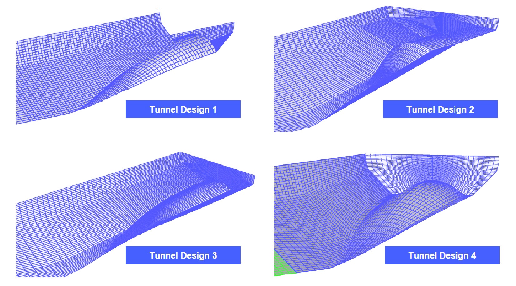
Following the successful design of the forebody, which had a lower wave-making resistance, the development and refinement of the aft body part of any vessel is challenging due to complex viscous flow activity of the wake flow interacting with the vessel’s propulsor. The selection of a shallow tunnel (or propeller pocket) to enable the fitting of a relatively large diameter propeller with reduced tip losses and reduced shaft inclination made this task even more demanding. The shallow tunnel would however help to smooth the sharp wake peak at the bottom of the V shape hull in the propeller plane as well as provide more flexibility for relaxed tip clearances. In selecting the most favourable after body configuration the four different stern designs shown in Fig. 7 were analysed using a RANS based viscous solver (FLUENT) to compare their efficiencies in terms of viscous pressure resistance. The four stern forms were modelled with the finalised anti-slamming bulbous bow design for an accurate numerical prediction. In this calculation, the hull form was considered as a monohull rather than a catamaran in order to save computational time.
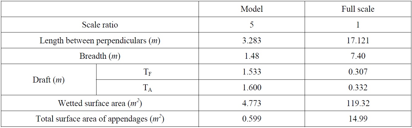
Table 2 shows the computational ship-model dimension, model speed and wetted surface area used in the calculation. This analysis led to the selection of the aft body design, which gave the least viscous pressure resistance. The results of this investigation are given in Table 3. Tunnel No.3 was selected as a stern form as it demonstrated the lowest viscous pressure resistance. The form factor from the RANS computation, using a double-body model, was calculated using Eq. (1).
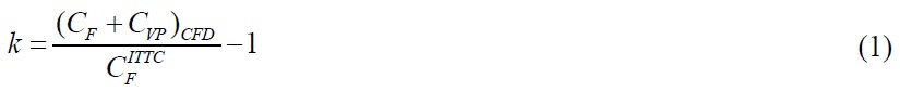
where CF is the frictional resistance coefficient from computation, CVP is the viscous pressure resistance coefficient from computation and CFITTC is the ‘ITTC 1957 model-ship correlation line’.
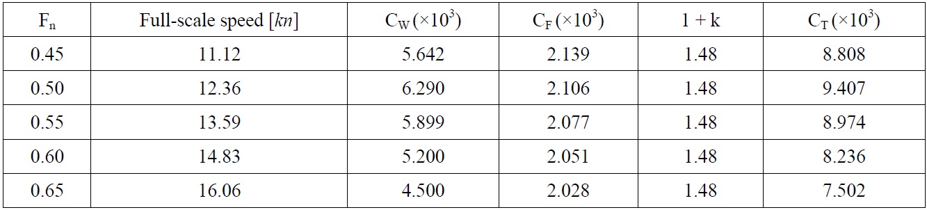
Once the optimum hull form (Tunnel No.3) was obtained, the RANS computation was repeated using two demi hulls with the optimum hull separation (s/L = 0.3) and the computed form factor is given in Table 4. As expected a catamaran with hull clearance produced a higher form factor than that of the mono hull designs due to viscous interaction between the demi hulls. This resistance interference was generated by a variation of velocity field and pressure around the demi hulls. The wave-making resistance was also re-analysed using a non-linear approach based panel code to improve the accuracy. Within this framework, the total resistance coefficient was estimated numerically using the Prohaska method by the formation of the form factor and wave-making resistance; the result is given in Table 5. It is important to note however that the numerical analysis does not take into account the appendage effect (skeg and rudder) on the resistance at this stage.
[Table 2] Computational ship-model dimensions for numerical prediction.
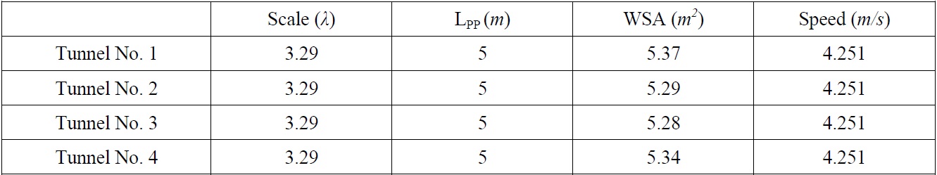
Computational ship-model dimensions for numerical prediction.
[Table 3] Computed form factor prediction as mono-hull.
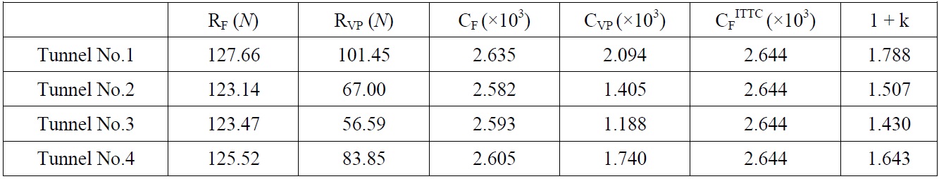
Computed form factor prediction as mono-hull.
[Table 4] Computed form factor prediction as demi hulls.

Computed form factor prediction as demi hulls.
[Table 5] Computed resistance coefficient.

Computed resistance coefficient.
>
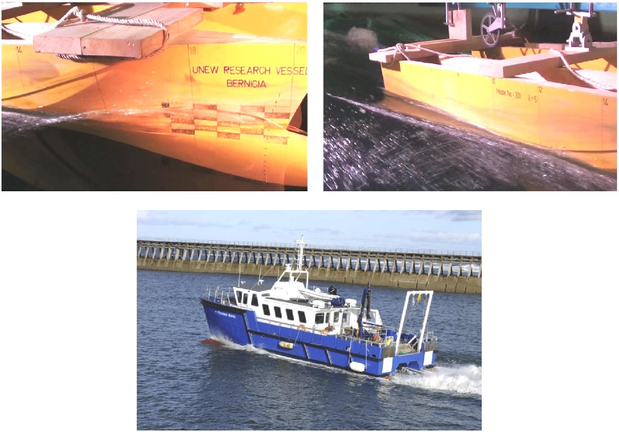
Model test verification of bare hull resistance
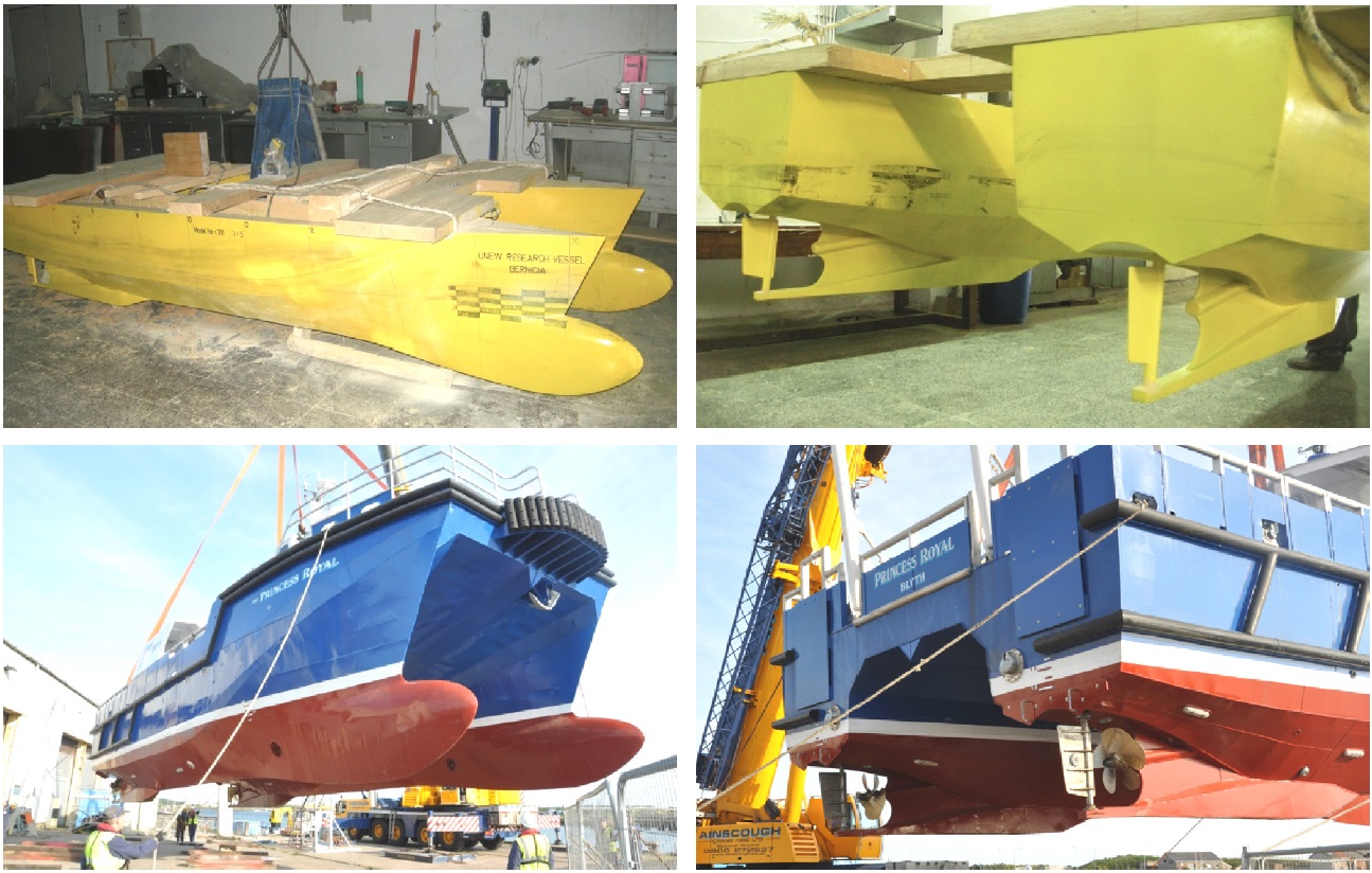
A set of comparative model experiments was deemed necessary to validate the overall worthiness of the development of Deep-V catamaran design. The model tests included resistance, wake flow and self-propulsion tests using relatively large scale hull models, Soylemez and Korkut (2010). The first stage of these model tests, mainly discussed in this paper, was the resistance test. A wooden model with a scale of 1 : 5 was constructed in the workshop of Ata Nutku Ship Model Testing Laboratory in Istanbul Technical University and tested in the 160
[Table 6] Model and ship dimensions for full load departure.
Model and ship dimensions for full load departure.
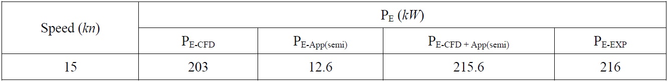
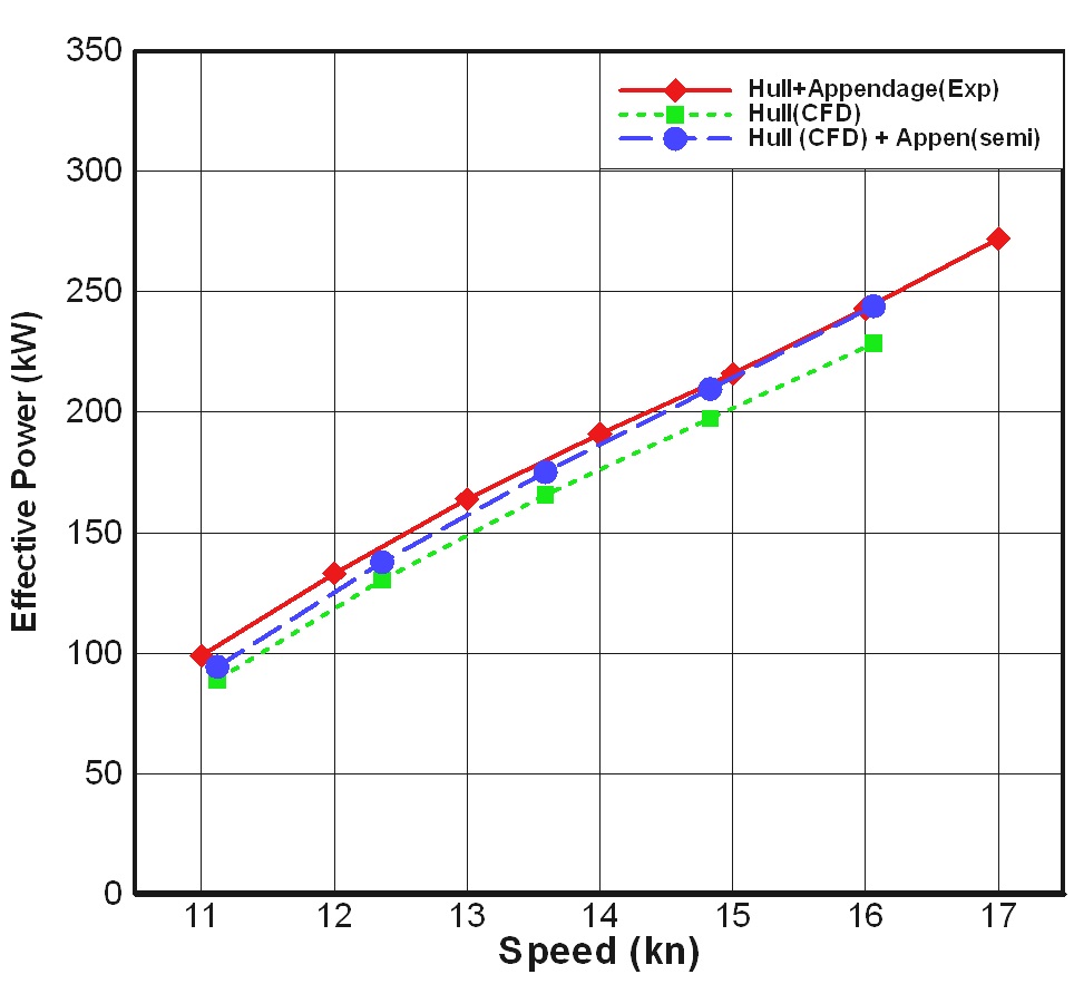
The extrapolation of the model resistance to the full-scale effective power was conducted using the Froude extrapolation (2D) approach from the model tests whilst the form factor (3D) approach was used in the CFD computation. The comparison of the effective power prediction between the numerical and experimental predictions at the design draught condition is given in Fig. 10. In the predictions the static water level at zero speed was used as the reference for the reference wetted surface. It is clear that there is good agreement between the computed values of the effective power and the experimentally derived values. The CFD computation provided promising results in the wide range of ship speed, resulting in percentage difference in average 7%. The main difference between the experimental and numerical results could be attributed to the exclusion of the appendages in the computations. In order to check the influence of appendages on the resistance a semi-empirical approach was used to take into account the effects of the large keel, skeg and rudder (Holtrop and Mennen, 1982). Table 7 shows some details of the appendages and prediction at the design speed (15
[Table 7] Effective power prediction including appendages.

Effective power prediction including appendages.
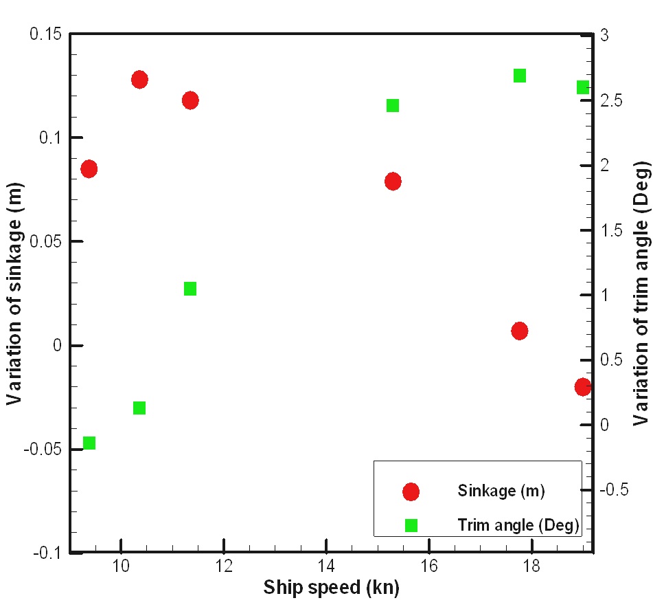
During the resistance tests, sinkage and trim angle measurements were taken using a high-speed camera system and results are shown in Fig. 11. Trim angle was reached up to 3
This paper presented the further design development of a unique Deep-V catamaran fitted with a novel anti-slamming bulbous bow and tunnel stern to improve its operational efficiency. The design was based on the first systematic UNEW-DVC series and the adopted approach for the design was presented along with the selected numerical tools that were selected to perform the CFD analysis. An assessment of the numerical predictions of the hull resistance was compared against physical model test results. From the study of the hull form refinement in conjunction with the experimental and numerical work the following conclusions can be drawn:
(1) Full capitalisation of the benefits from ‘Deep-V Catamaran’ concept requires close attention to the increase in the bare hull resistance due to the inclusion of anti-slamming bulbous bow and tunnel stern, and hence requires rigorous hull refinements using sophisticated computational tools and model tests.
(2) The investigation indicated that the anti-slamming bulb can give a significant improvement in the wave-making resistance coefficient compared to a vessel without a bulb; a maximum of 20% reduction in wave-making resistance is expected over a wide range of speed.
(3) The tunnel stern was introduced to enable the fitting of a relatively large diameter propeller with reduced tip losses and reduced shaft inclination. Four stern tunnel arrangements were analysed using RANS based viscous solvers and the optimum one (Tunnel stern No.3) was selected as it demonstrated the lowest viscous pressure resistance.
(4) The comparison of the CFD predictions with the model tests indicated satisfactory correlations, and thus CFD approach provided a useful tool in investigating the effect of catamaran resistance on further changes in hull form.
(5) In order to control the dynamic trim to secure the visibility for operators and prevent the resistance increase, further experimental investigations are underway to investigate the application of Trim Tab, Interceptor, Transom Wedges and Integrated Wedge Flap in the Newcastle University Towing Tank.