Recently, some concepts of floating offshore wind turbines (FOWT) have been designed and installed in deep sea greater than 50
A concept of spar type FOWT was defined by IEA Task 23 OC3 project to support a 5MW wind turbine based on the prototype Hywind (Jonkman et al., 2009). Scale model tests of OC3-Hywind had been carried out in the Wide Tank of the University of Ulsan (UOU) (Kim, 2011; Shin, 2011). Its results had a good agreement with numerical simulations.
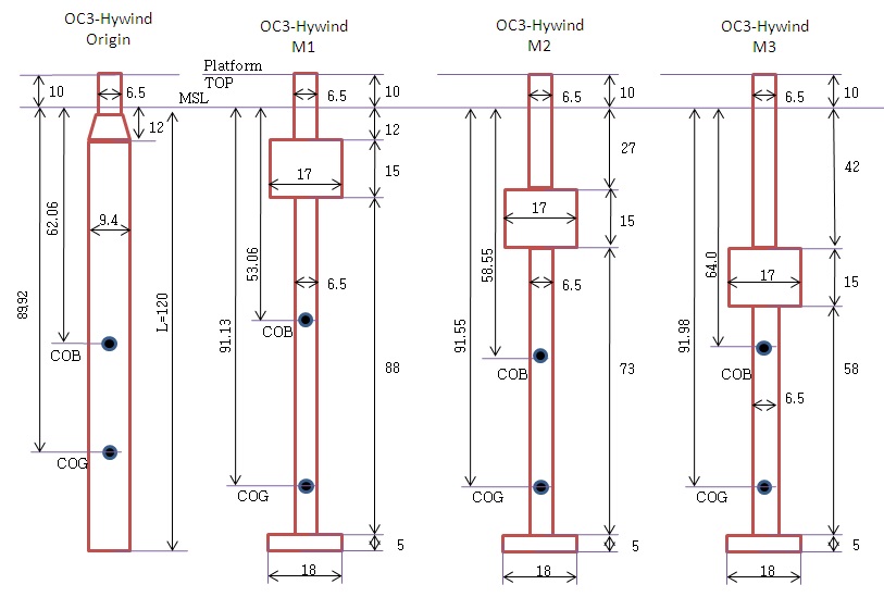
This study focuses on improvement of 5-MW FOWT platforms in deep water. We deploy three new platforms of which both mass and volume remain unchanged in comparison with OC3-Hywind. However, hydrodynamic and hydrostatic loads on platforms vary because the platforms have the ballast plate with a large diameter at the bottom and the ring cylinders at the top side of platform.
Three new platforms are called M1, M2 and M3, respectively and are shown in Fig. 1. Table 1 and Table 2 show general and different properties of three new platforms, respectively. Both mass and volume of platforms keep the same as those of OC3-Hywind. The shapes are different from each other, depending on the position of ring cylinders around the main structure.
The ring cylinder of M1 was located 12
[Table 1] General properties of three new platforms M1, M2 and M3.
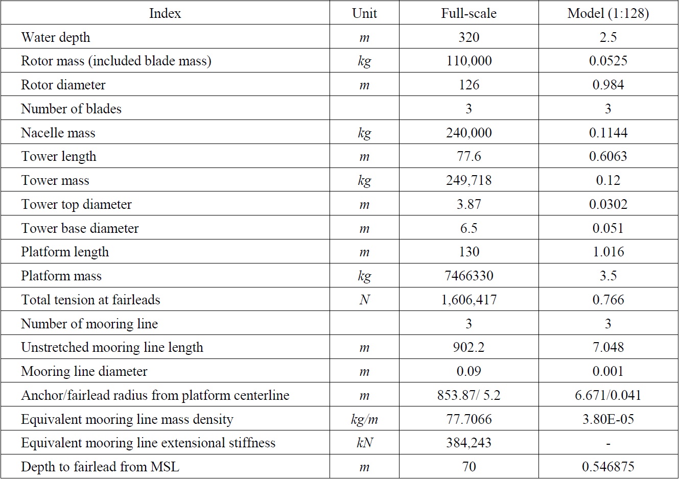
General properties of three new platforms M1, M2 and M3.
[Table 2] Different properties of three new platforms M1, M2 and M3.
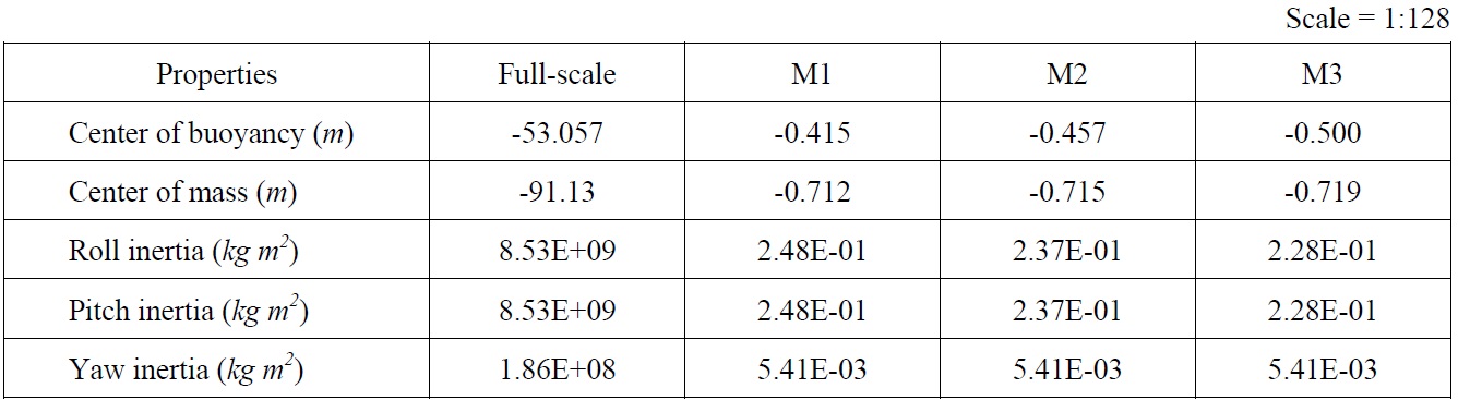
Different properties of three new platforms M1, M2 and M3.
The mooring system includes 3 mooring lines; the fairleads are located at a depth of 70.0
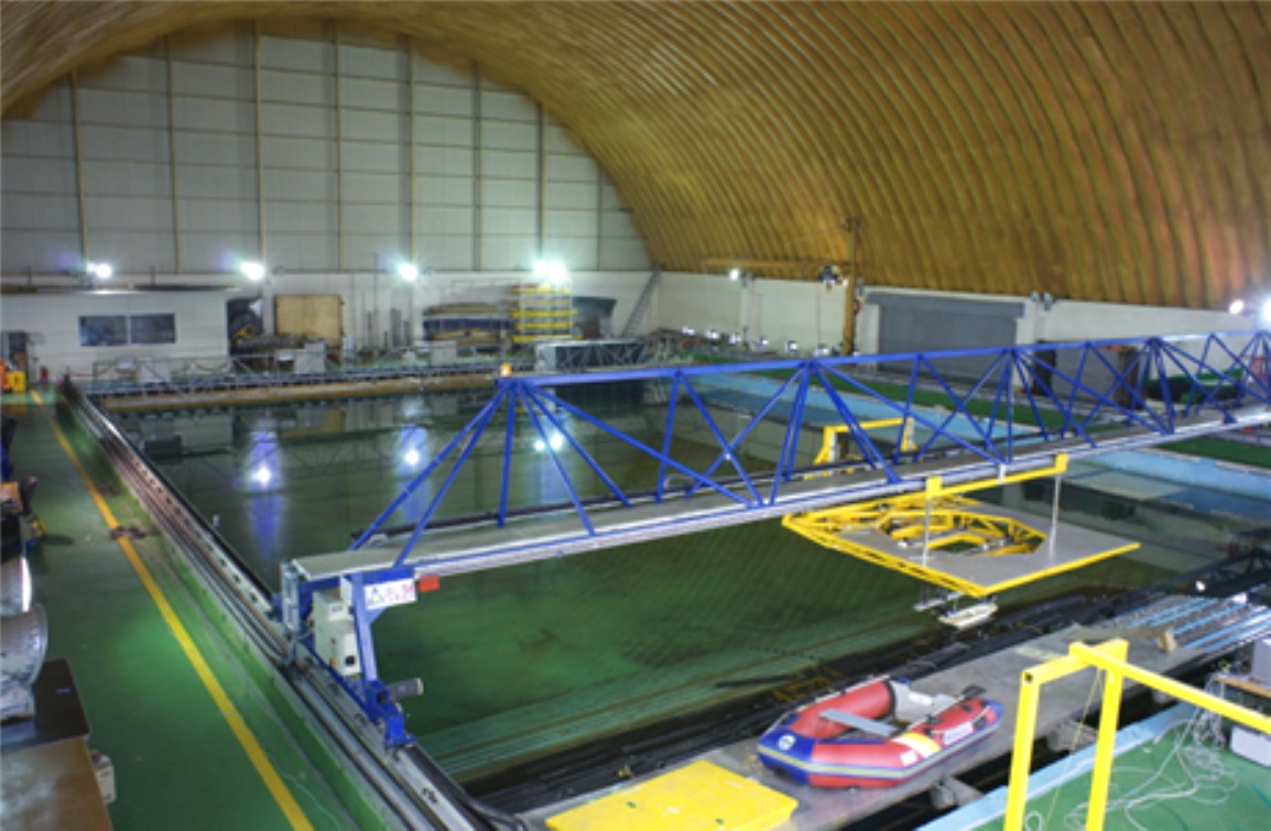
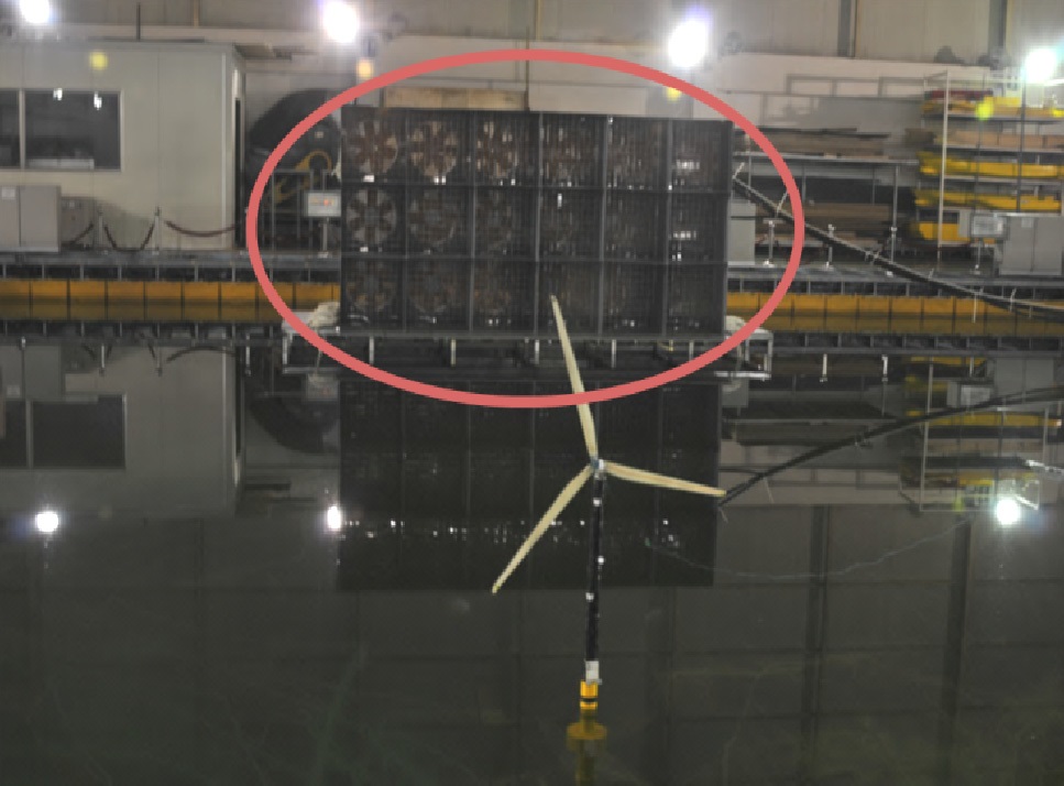
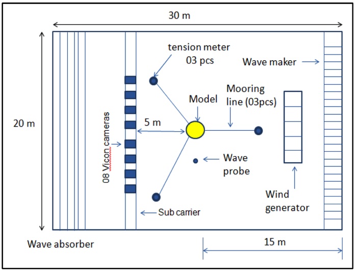
The scale model tests of 3 new platforms were carried out at the Ocean Engineering Wide Tank, UOU which is 30
The geometric model scale ratio is
The wide tank has a multi-directional wave maker system and a wind generator system in Fig. 3. Wavemaker can produce regular waves and irregular waves (ISSC, JONSWAP, Scott, ITTC, Neumann, Pierson-Moskowitz, etc.). The model was set at 15
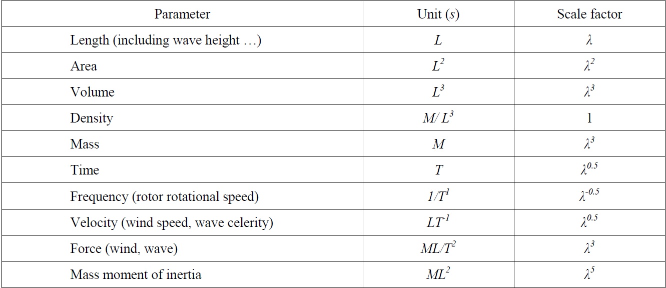
[Table 3] Scaling factors for floating wind turbine model testing.

Scaling factors for floating wind turbine model testing.
The wind generator in Fig. 3 is composed of eighteen fans and is used to create wind load acting on offshore wind turbines in scale model test. It can generate both steady wind and unsteady wind. Maximum wind speed is about 10
>
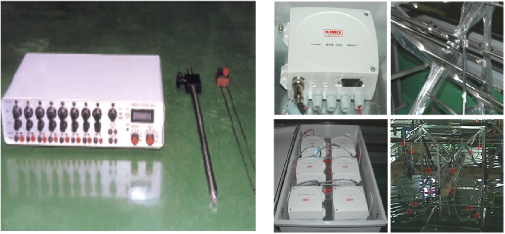
Measuring equipment (Sensor)
Wave probes, anemometers, RPM measurement device, water-proof tension meter, VICON cameras and passive markers are employed in order to measure wind, wave, rotor revolution, tension and motion, respectively.
Wave probes and anemometers in Fig. 5 are calibrated using a height gage and in the UOU Wind Tunnel, respectively.
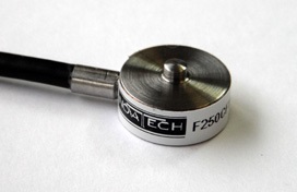
Tension meter is used to measure the tensile forces acting on mooring lines.
>
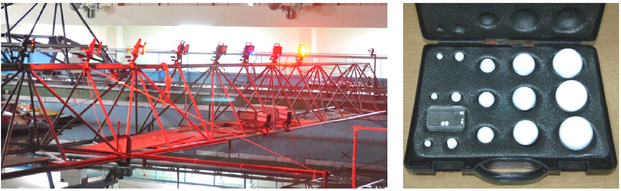
VICON camera and passive marker
VICON cameras measure the motion of structure as perceiving the infrared ray reflected from passive marker (Fig. 7). At least three markers are needed to measure the motion and they have to be stuck on the structure with distance 0.1~0.15
The 5MW offshore wind turbines in full scale operate with rotor speed 12.1
Rotor speed = 136.9 rpm , Mean wind speed = 1.007 m/s
Load cases in the model test are defined as follows:
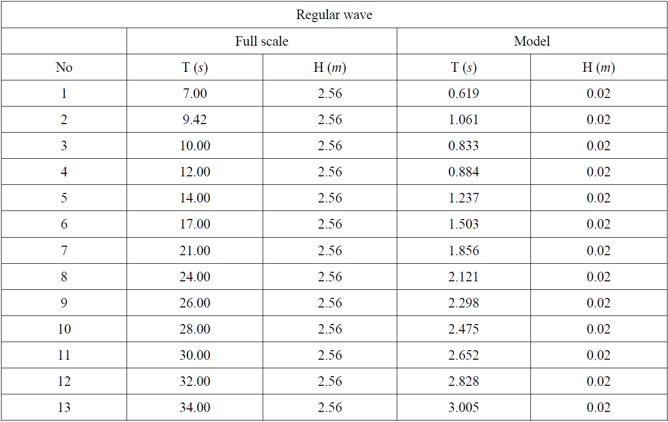
LC01: Regular waves, no wind, parked rotor.
LC02: Regular waves, mean wind speed, parked rotor.
LC03: Regular waves, mean wind speed and rotating rotor.
LC04: Irregular wave, no wind, parked rotor.
LC05: Irregular waves, mean wind speed, parked rotor.
LC06: Irregular waves, mean wind speed, rotating rotor.

Regular waves.

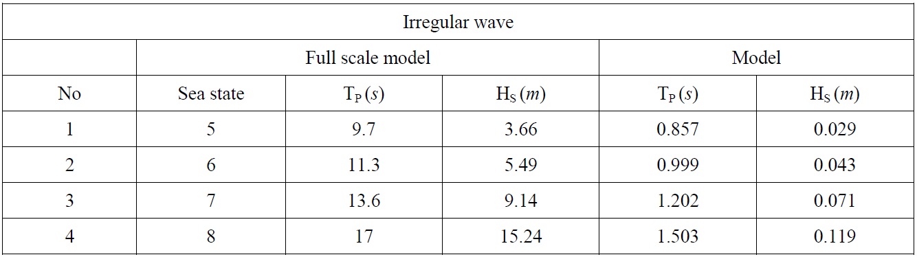
Irregular waves.
>
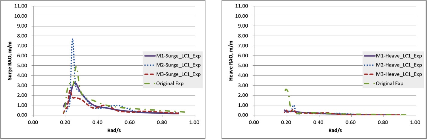
Response Amplitude Operator (RAO)
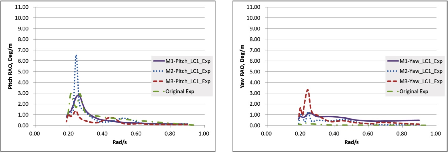
LC01 : Regular waves, no wind, parked rotor
In surge, heave and pitch, responses of M1and M3 are smaller than those of the original while M2 in surge and pitch shows peak values much higher than those of the original (Figs. 8 and 9).
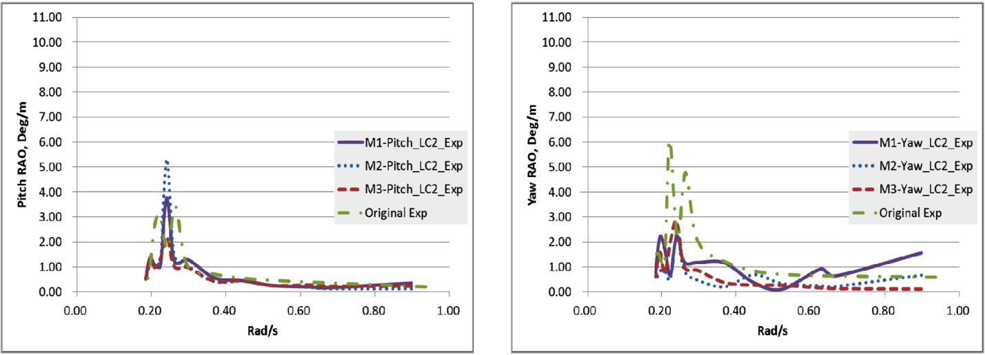
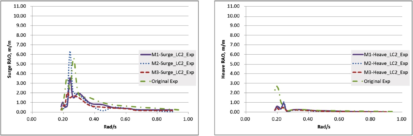
LC02 : Regular waves, mean wind speed, parked rotor
As in LC01, in surge, heave and pitch, responses of M1and M3 are smaller than those of the original while M2 in surge and pitch shows peak values much higher than those of the original (Figs. 10 and 11). The large yaw angle of the original OC3 Hywind may result from no crow-foot delta mooring which was designed for additional yaw stiffness in the full scale of original.
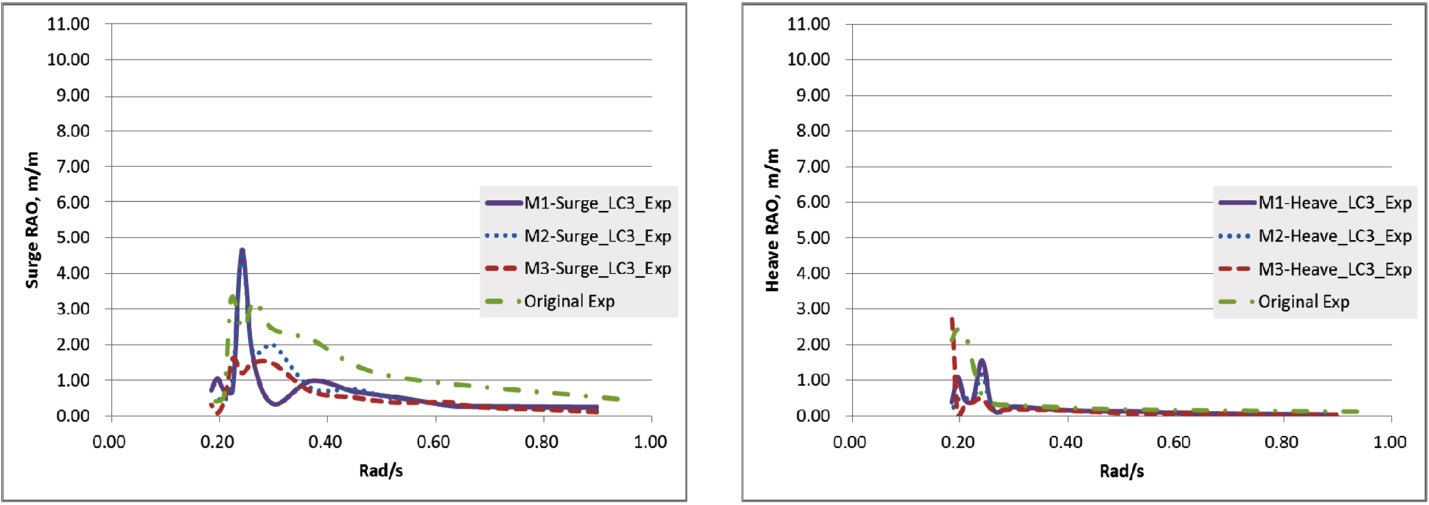
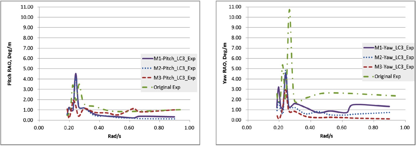
LC03 : Regular waves, mean wind speed and rotating rotor
In every mode, M3 shows smaller responses than M1, M2 and the original under the combined environmental condition including rotor rotation effect (Figs. 12 and 13). In LC01~LC03 with regular waves, M3 shows the best performance. Heave RAO of all models are similar but difference in peak value.
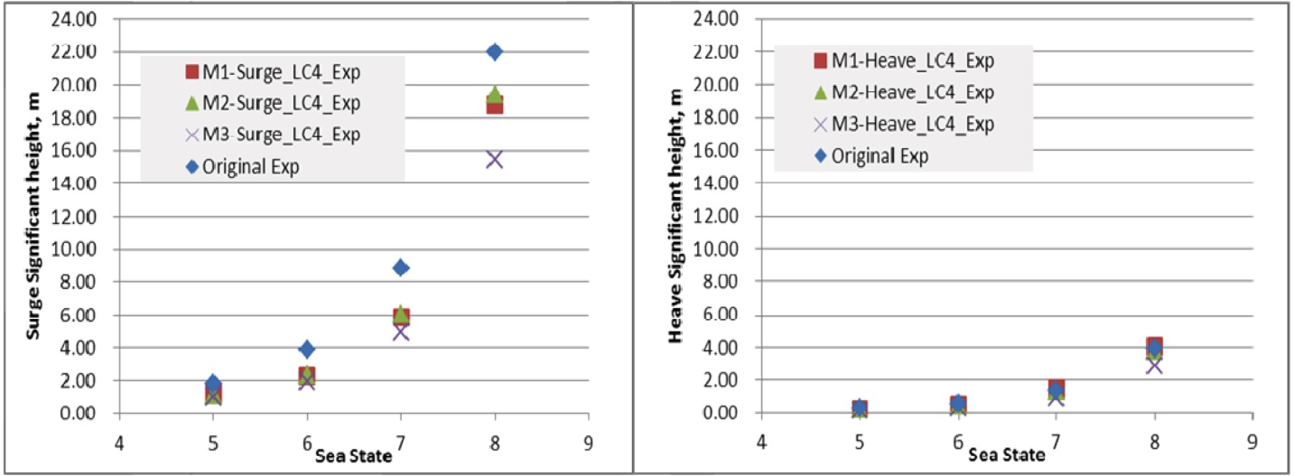
The behavior of floating offshore wind turbines in irregular waves is expressed in terms of significant height of motion responses at specified sea states. Model tests were carried out in sea states 5~8.
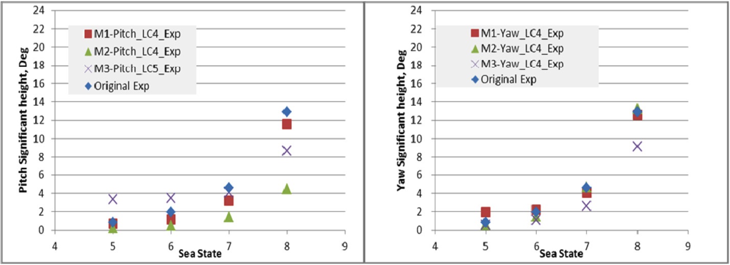
LC04 : Irregular wave, no wind, parked rotor
In surge, significant motions of M1~M3 are smaller than those of the original. In heave, significant motions of all models are similar to each other. In pitch, M2 in irregular waves shows the smallest significant motion in contrast to regular waves. In yaw M3 shows the smallest response. M3 shows the smallest responses in all modes except in pitch.
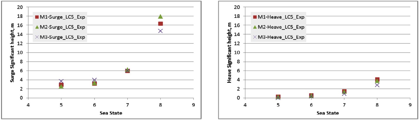
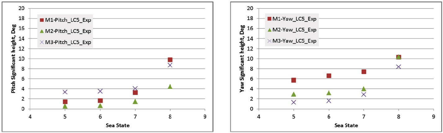
LC05 : Irregular waves, mean wind speed, parked rotor
As in LC04, M3 shows the smallest significant motion in all modes except in pitch (Figs. 16 and 17).
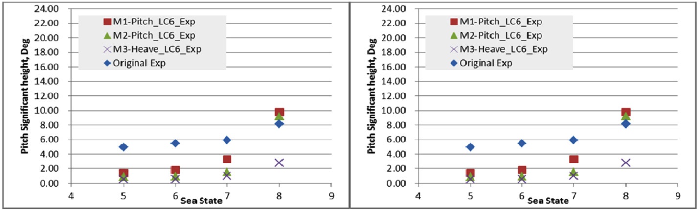
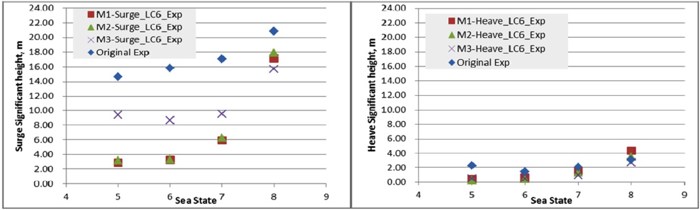
LC06 : Irregular waves, mean wind speed, rotating rotor
In surge, significant motions of M3 is larger than those of M1 and M2 in sea states 5~7 but smaller in sea state 8. In heave, pitch and yaw, M3 shows smaller significant motions than those of other models.
In this paper, scale model tests had been carried out in order to investigate the motion characteristics of three new floating offshore wind turbines, M1~M3. The load cases included effects of wave, wind and rotating rotor. The test results of M1~M3 were compared with those of the original OC3-Hywind.
The spar with ring cylinders causes water particles to be much more excited than without rings, that is, ring cylinders induce the increase in both added mass and damping and, in turn, both the increase in motion period and the decrease in motion height. As we expected, in most load cases, the responses of M1~M3 are smaller than those of the original OC3-Hywind.
Regular waves : M3 shows the best performance in LC01~LC03.
Irregular waves : M3 shows the best performance, except pitch in both LC04 and LC05 and except surge in LC06.
It is concluded that three new platforms, M1~M3 have better motion characteristics than the spar of the original OC3- Hywind based on the model test results. Specially, M3 is recommended to a good platform in extreme weather conditions. In near future researches, low Reynolds effects on the Froude scaled rotor and wind will be investigated.