At the present time, we are alarmed by depletion of fossil energy and the negative effects of accelerated fossil fuel consumption on the environment. To minimize world dependence on fossil fuels, nuclear energy ought to do more than generating electricity since electricity accounts for a mere 17% of world final energy consumption [1]. The high temperature gas reactor (HTGR) with unique design has several advantages to accomplish this goal.
The HTGR is considered to be the nearest term deployable system of the next-generation fission reactors thanks to decades of development in several countries [2,3]. It is based on a helium-cooled, graphite-constructed, and ceramic-fueled core. The inert coolant and the heat-resistant structure allow a core outlet temperature of up to 950℃ to be attained, well exceeding the temperature of the other existing and foreseeable reactor options.
The greater temperature range opens the possibility for diverse applications. Electricity can be generated at 50% efficiency. Process steam can be cogenerated and supplied in a wide range of temperatures and pressures demanded by petroleum and petrochemical industries. High temperature heat can be produced onsite for use in manufacturing fertilizer and steel. Large-scale hydrogen production can be carried out from HTGR-heated water-splitting processes to make industrial uses and future transportation fuel.
The HTGR safety meets requirement for industrial cogeneration. The reactor is designed to be coolable in the event of severe accidents even without electric power or an emergency core cooling system. Nuclear chain reaction would cease in core in the presence of an abnormal rise in core temperature. The decay heat is removable by means of in-core conduction and ex-vessel radiation and natural convection. The reactor fuel and structures are kept well within allowable temperatures of the design. Without possibility of a fuel failure, fission products are secured inside the fuel. By replying only on intrinsic design features, rather than active systems, to stop and cool the reactor in an emergency, the HTGR essentially precludes such risk as core melt or the release of radioactive materials that would disallow co-siting the reactor with process industries as is necessary for economical cogeneration.
A number of HTGR plant designs already exist. The HTR-Module design couples a pebble-bed core to a steam generator for cogeneration of power and steam at 200 MWt core power and 700℃ core outlet [4] and alternatively to a process heat exchanger for reforming of fossil fuels at 170 MWt core power and 950℃ core outlet [5]. The MGRGT uses a similar core but replaces the steam turbine with a direct cycle gas turbine. At 850℃ core outlet, it generates electricity at 45% efficiency, comparied to 33% of the current water cooled reactors, and can allow other processes such as desalination without sacrificing electrical efficiency [6]. The 60 MWt ACACIA uses an indirect cycle gas turbine and employs a cartridge core for refueling to ease distributed installations [7]. Two types of applications were shown: a cogeneration version with 18MWe electric output and 28 t/h process steam, and a combined cycle 23MWe electricity-only version. Recent designs have introduced hydrogen production including the 200 MWt PMR-200 [8] and the 600 MWt H2-MHR [9]. In the latter case, the two different hydrogen production technologies investigated are thermochemical water splitting process and high temperature electrolysis.
This work is a pre-feasibility design study performed by the Japan Atomic Energy Agency (JAEA) in cooperation with industries for a small modular HTGR plant of 50MWt, namely HTR50S. The plant is unique in that its construction begins with building a base commercial system for combined heat and power production and expands by adding advanced components and systems to upgrade performance and expand applications. Accordingly, the construction proceeds in three steps. Initially, the reactor is built and operated on the successfully-proven fuel and operating parameters from JAEA’s engineering test reactor. The balance of the plant is based on a conventional steam turbine to generate power and process steam. The emphasis on using the existing technology and experience is intended to minimize initial construction uncertainty and potential delay that could result from pursuing major new design validation. In the second step, a higher performance fuel will be introduced. It allows for higher core outlet temperature and better fuel cycle economics to be attained. Furthermore, an intermediate heat exchanger will be installed in the reactor plant to cogenerate high temperature heat at 850℃. The heat is exported to a new gas turbine that is operated in series with the commercial steam turbine. In the third step of construction, a thermochemical process system will be installed to demonstrate nuclear-heated hydrogen production by decomposing water molecules.
This completes the small modular reactor HTR50S construction for multiple applications including electricity generation, high temperature heat cogeneration, nuclear hydrogen, process steam supply, and district heating.
2. REVIEW OF DESIGN BASE IN JAEA
2.1 HTTR - High Temperature Engineering Test Reactor
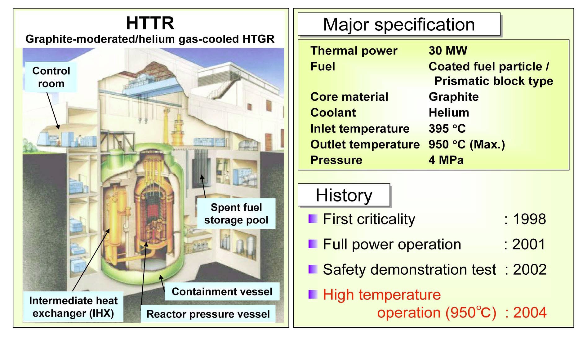
Japanese industries including Toshiba, Mitsubishi Heavy Industries, Fuji Electric, Toyo Tanso, Nuclear Fuel Industries and others had developed the HTGR jointly with JAEA [10]. Such industry-public cooperation culminated in the construction of the HTTR at JAEA’s Oarai Research and Development Center [11,12]. The 30 MWt, 950℃ HTTR, which has been in successful operation since 1998, is the largest and highest-temperature HTGR operating in the world today.
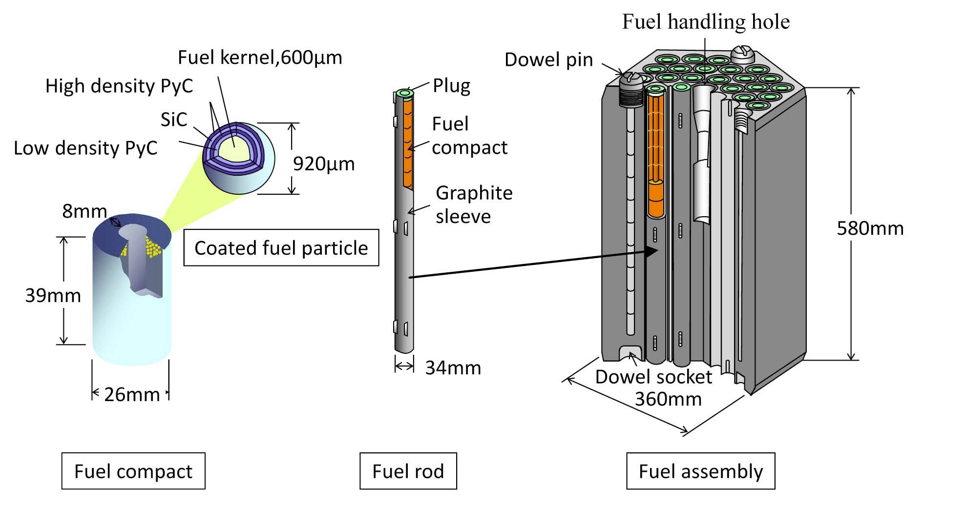
Figure 1 shows the system structure, design parameters, and brief operation history of the HTTR. The reactor core consists of a cylindrical pile of 150 prismatic fuel blocks surrounded by graphite reflector blocks. Figure 2 shows the assembly of a fuel block. The fuel compact is a graphite
matrix dispersed of thousands of TRISO-coated fuel particles with a UO2 kernel. A fuel rod contains about a dozen of fuel compacts in tubular graphite sleeve. Over thirty fuel rods are inserted in the bores of a graphite fuel block. The helium coolant flows in the thin annulus between the fuel rod and the bore.
The HTTR attained the first criticality in 1998, and full power operation with a reactor outlet temperature of 850℃ in 2001. The full power operation at 950℃ outlet temperature was first achieved in 2004 [13]. In 2010, a 50- day full-power operation near 950℃ outlet temperature was carried out, which confirmed stable reactor performance by measurements of fuel integrity, high temperature equipment, and coolant chemistry in the sufficiently long period of operation [14]. Safety tests for demonstrating the passive and inherent safety performance against severe accidents have been conducted since 2002. A recent safety demonstration test of a loss of forced cooling without scram showed that the fuel was not exposed to any overheating and the reactor remained stable despite occurrence of recriticality and that the negligible power generated was sufficiently removed by ex-vessel cooling system[15].
2.2 GTHTR300 Commercial Plant Series
Similar to the development of the HTTR, JAEA collaborated with the Japanese heavy industries in completing the basic design of commercial GTHTR300 that combines a 600MWt HTGR and a direct cycle gas turbine for power generation [16]. The design validation was carried out by tests of key gas-turbine components in one-third scale including a multi-stage helium compressor [17] and a magnetic bearing [18]. The evaluation on the GTHTR300 safety [19] and economics [20] was also performed.
Based on the fuel performance in the HTTR and additional irradiation test of high burnup fuel particles, a new fuel specification was developed for the GTHTR300 fuel. The key modification was an integral fuel rod design that eliminates the sleeve used in the HTTR fuel. Instead, the fuel compacts are aligned and supported on a central graphite rod as detailed in reference [21]. Elimination of the sleeve removes the heat transfer resistance of the gap between the sleeve and fuel compact, which keeps the fuel temperature lower at the higher power density and higher burnup commercial core. Due mainly to the integral fuel rod design, the allowable core average power density of 5.4 MW/m3 and fuel burnup of 120 GWd/t are both significantly higher for the GTHTR300 than the 2.5 MW/m3 and 22 GWd/t of the HTTR [21]. The performance integrity of the fuel has been shown for up to a maximum burnup of 150GWd/t [22,23].
The core is refueled by exchanging a half core of fuel blocks in each two year interval. A sandwich shuffling method is applied, in which one out of every two axial fuel blocks is discharged from the core and the remaining one is shifted one block downward to make space for loading a fresh fuel block. The refueling scheme is repeated in every refueling over the plant life. The load factor is more than 90% including planned and forced outages. The careful core physics design is performed to minimize the power and temperature peaking in the core, which reduces the maximum fuel temperature during passive core conduction cooldown in an accident.
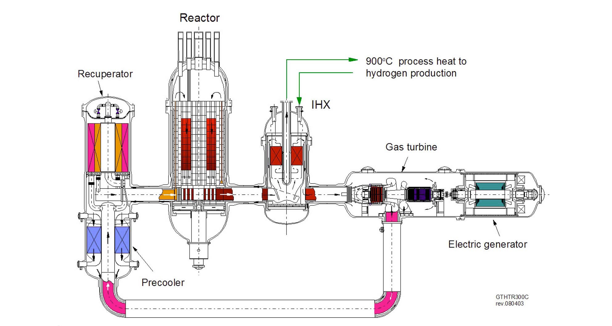
Upon completing the basic design, a design series was created by developing an alternate design for hydrogen cogeneration, named the GTHTR300C [24-26]. The GTHTR300C shown in Figure 3 shares common equipment technologies and system configuration with GTHTR300 with the exception that an intermediate heat exchanger (IHX) is installed between the reactor and the gas turbine. The IHX is used to transfer a share of reactor thermal power as nuclear process heat to a distant hydrogen production process or to other high-temperature process heat applications. The minor electricity need to power the hydrogen process is supplied in house from the efficient gas turbine power cogeneration. The GTHTR300C can be applied to meet the energy and hydrogen consumption in directreduction steelmaking [27]. Other cogeneration applications including district heating and desalination without sacrificing the power generation have been reported [28].
2.3 IS hydrogen Production Process
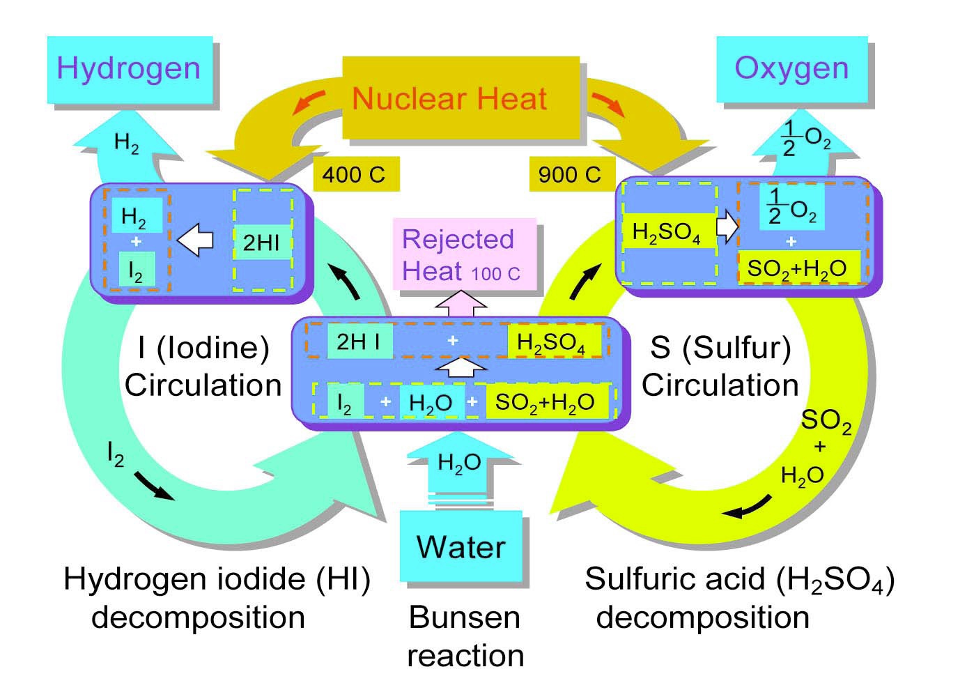
Research and development on the thermochemical water-splitting cycle using iodine and sulfur reagents has been performed in JAEA to prepare for a large-scale hydrogen production method [29]. In the IS process, inter-cyclic operation of following three chemical reactions (1)-(3) as shown in Figure 4 takes place with a net result of reaction (4) decomposing water “thermally” into hydrogen and oxygen using heat at temperatures around 900℃, which can be produced by the HTGR;


Here, the reaction (1), known as Bunsen reaction, proceeds exothermically as the SO2 gas absorption reaction by iodine-water mixture. The produced HI and H2SO4 can be separated by liquid-liquid phase separation of sulfuric acid and HIx solution. The reaction (2) is slightly endothermic and can be carried out in gas phase using catalysts. Reaction (3) proceeds in two steps, i.e.,


Reaction (5) takes place spontaneously in the temperature range of 300 - 500℃, while the reaction (6) takes place in temperature range of 750 - 850℃ in the presence of a catalyst. Here, the HTGR is uniquely designed to produce the nuclear heat necessary to drive the intensive endothermic high temperature reactions of H2SO4 decomposition to completion.
Feasibility of closed-cycle water splitting has been demonstrated by coupling the Bunsen reaction, thermal decomposition of hydrogen iodide and that of sulfuric acid. In June 2004, continuous hydrogen production was achieved with a hydrogen production rate of about 31 NL/h for 1 week [30]. Studies are in progress to realize efficient hydrogen production. Also, development of all major chemical process reactors, especially those used in the corrosive process environment of sulfuric acid vaporization and decomposition. Their trial fabrication has been carried out using existing industrial materials to validate practical construction [31]. Presently, a R&D program is underway to fabricate the components, including Bunsen reactor, H2SO4 and HI decomposers, assemble them in test loops, and test-examine their integrity in the actual process environments of the IS process at temperature of 950℃ and in effective production scale of 150NL/h hy-drogen [32].
3. SMALL MODULAR REACTOR DESIGN: HTR50S
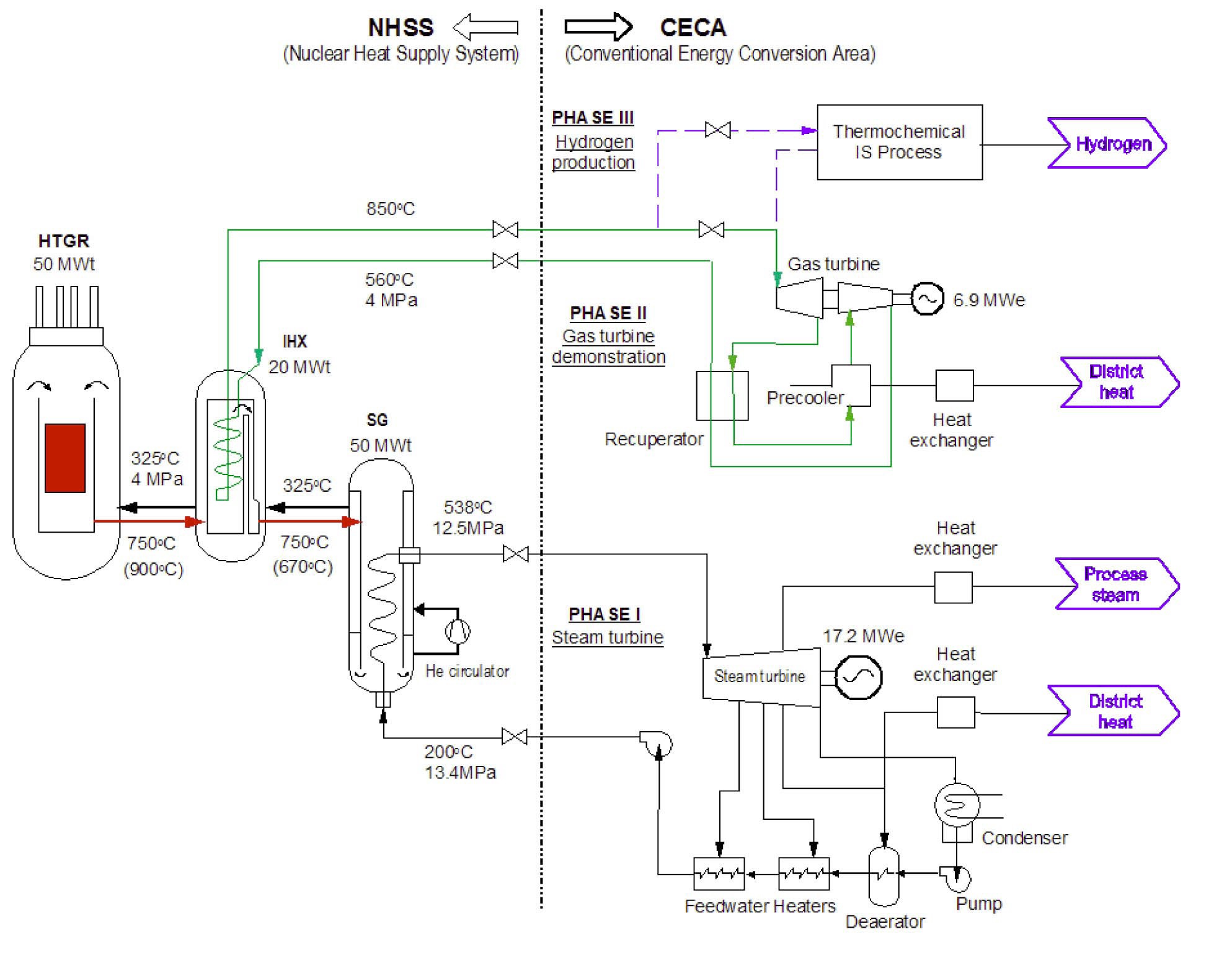
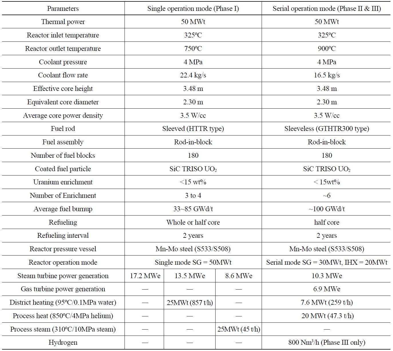
The plant system consists of a nuclear heat supply system area and an energy conversion area as shown in Figure 5. As introduced earlier, the plant is constructed in steps or phases. The plant performance and production specifications given in Table 1 are upgraded stepwise.
In the initial phase construction, a steam generator (SG) of 50 MWt is connected to a conventional steam turbine system for combined heat and power production. The reactor outlet temperature is 750℃ so that the conventional alloy 800H whose allowable temperature limit is 760℃ can be used for the SG tube material. The reactor inlet temperature is set to 325℃ in order to provide a sufficient temperature margin for the RPV of carbon steel SA533/SA508. This steel is used for the LWR RPV and its allowable temperature limit is 371℃during normal operation. Since its allowance stress is greater than the 2¼Cr-1Mo steel used for HTTR, the RPV of the HTR50S is thinner and lighter than the HTTR while the primary coolant pressure is the same as in the HTTR.
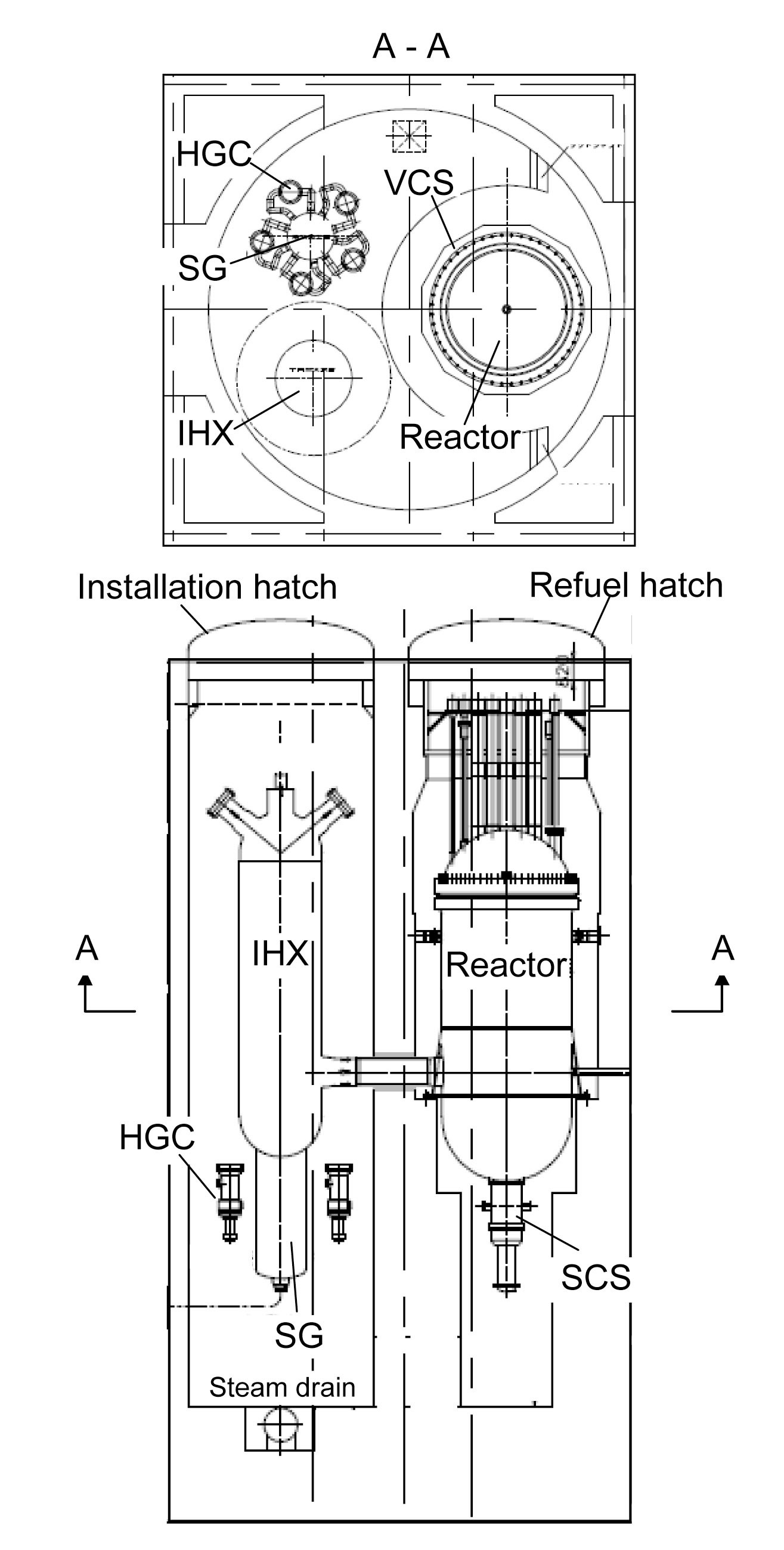
During Phase II construction, an IHX will be installed between the reactor and the SG as shown in Figure 6. This system layout is intended to demonstrate the design features of the GTHTR300 design series including:
Inline side-by-side layout of primary system vessels,
piping, and associated supports
Pressure vessel cooling provided by intrinsic flow bypass
Serial cogeneration of high temperature heat and electrical power
The construction modification will require that the reactor piping connected to the SG in Phase I be cut and reconnected to the IHX. Similarly the SG is reconnected for the IHX. The spaces and equipment access paths required to carry out the system modification are allocated in the reactor building and containment.
Also for the purpose of demonstrating the GTHTR300 series, a closed cycle helium gas turbine system for combined power generation and district heating will be built in the energy conversion area. The specific heat of helium is five times that of air. As a result, it is much more difficult to compress and expand helium such that the number of stages in helium gas turbine tend to be more than those of conventional open cycle air gas turbine. Furthermore, because the closed cycle is pressurized to 2 MPa at the compressor inlet, the specific compressor volume flow is
[Table 1.] Design Specification of HTR50S

Design Specification of HTR50S
extremely small relative to the open cycle where the compressor inlet operates at atmospheric pressure. These unique conditions lead to what appears to be a large number of blade rows with small blade height populated in an essentially parallel flow path in the helium gas turbine’s compressor. The slender flow path gives rise to aerodynamic losses such as those caused by separated flow on the compressor blades, which may result in operational instability of the gas turbine.
To overcome this challenge, JAEA has tested a model helium compressor as a part of the GTHTR300 design validation and successful results were obtained. In order to apply this proven blade design [17] in the present gas turbine, a thermal power rating of 20 MWt at minimum is determined to be necessary from the IHX.
Another design requirement imposed by the gas turbine cycle to the IHX is the relatively high inlet temperature of the secondary side. This temperature is well above the reactor inlet temperature and the desired reactor inlet temperature can only be attained by serial operation of the IHX and SG, which results in a split of the reactor thermal power between the two components. Given the previouslydetermined IHX rating, the thermal share of the SG is thus 30 MWt in serial operation. The SG is designed to be operable in the standalone mode of 50 MWt at 750℃ primary side inlet or in serial mode of 30 MWt at 670℃ primary
inlet. The steam condition remains to be the same at 12.5 MPa and 538℃ at the steam nozzle in both operation modes.
The heating to the gas turbine cycle, and later to the hydrogen process, demands 850℃ outlet temperature in the secondary side of the IHX. Considering 50℃ temperature difference across the hot end of the IHX gives 900℃ inlet to the IHX primary side. The reactor outlet temperature is thus raised to 900℃.
In the third phase construction, a hydrogen production plant based on the IS-process will be added in a third loop, which is connected upstream of the gas turbine in order to model after the serial operation of the GTHTR300C hydrogen cogeneration mode. The objectives of coupling the hydrogen plant are to develop the first-of-a-kind licensing application experience for the thermodynamic coupling of the conventional high temperature process to the nuclear plant and to demonstrate nuclear-heated hydrogen production.
The reactor design resembles the HTTR, in particular it shares the same diameter of the reactor pressure vessel. However, the core power is raised to 50 MWt. The extra power is gained firstly by adding a layer of fuel blocks, making 180 fuel blocks in total. The resulting active core is 3.5 m in height by 3.1 m in effective diameter. The cylindrical core consists of 30 columns of fuel blocks as it is in the HTTR.
The core power is gained additionally by increasing the core power density. As described earlier, the HTR50S is designed to allow dual core outlet temperatures of 750℃ and 900℃. By reducing core outlet temperature to 750℃ below the 850 - 950℃ range of the HTTR, the core power density can be increased by 40% to 3.5 MW/m3 from the HTTR core under the same fuel operating temperature limit. This is achieved even if the number of fuel enrichment is reduced to three from the HTTR’s twelve. The operating period between refueling is increased to 730 days (two years) from the HTTR’s 660 days while keeping the number of burnable poison types used in core unchanged at two. The fuel design is also the same as the HTTR. However, the average fuel burnup is increased by about 50% to 33 GWt/d.
The fuel burnup rate can be further increased to 86 GWt/d by introducing the following two design measures: First, fuel shuffling is performed during refueling, in which a half core of spent fuel blocks are removed. The other half of the partially spent fuel blocks are moved axially to the positions vacated by the removed spent fuel and their vacated spaces are then occupied by the newly-loaded fresh fuel blocks. Such reshuffling scheme is intended to minimize axial power peaking in order to keep the fuel operating temperature below the design limit of 1495℃ during the extended fuel burnup period of 4 years. Second, a new fuel particle with a smaller kernel diameter and redistributed thickness of TRISO-coating layers is employed. The integrity of the particle design has been confirmed by analysis under the maximum fuel temperature and burnup of the HTR50S. Presently the new fuel is undergoing irradiation test for performance confirmation.
To increase core outlet temperature to 900℃, the fuel rod structural design needs to be changed from the HTTR’s sleeved fuel rod design to the GTHTR300’s integral fuel rod design as the latter permits a large reduction in fuel operating temperature, as described earlier in Section 2.2. In the HTR50S, such reduction is estimated to be roughly 150℃, which makes it possible to produce the desired 900℃ core outlet temperature at core power density and fuel operating temperature similar to those of the earlier core design at 750℃ outlet temperature.
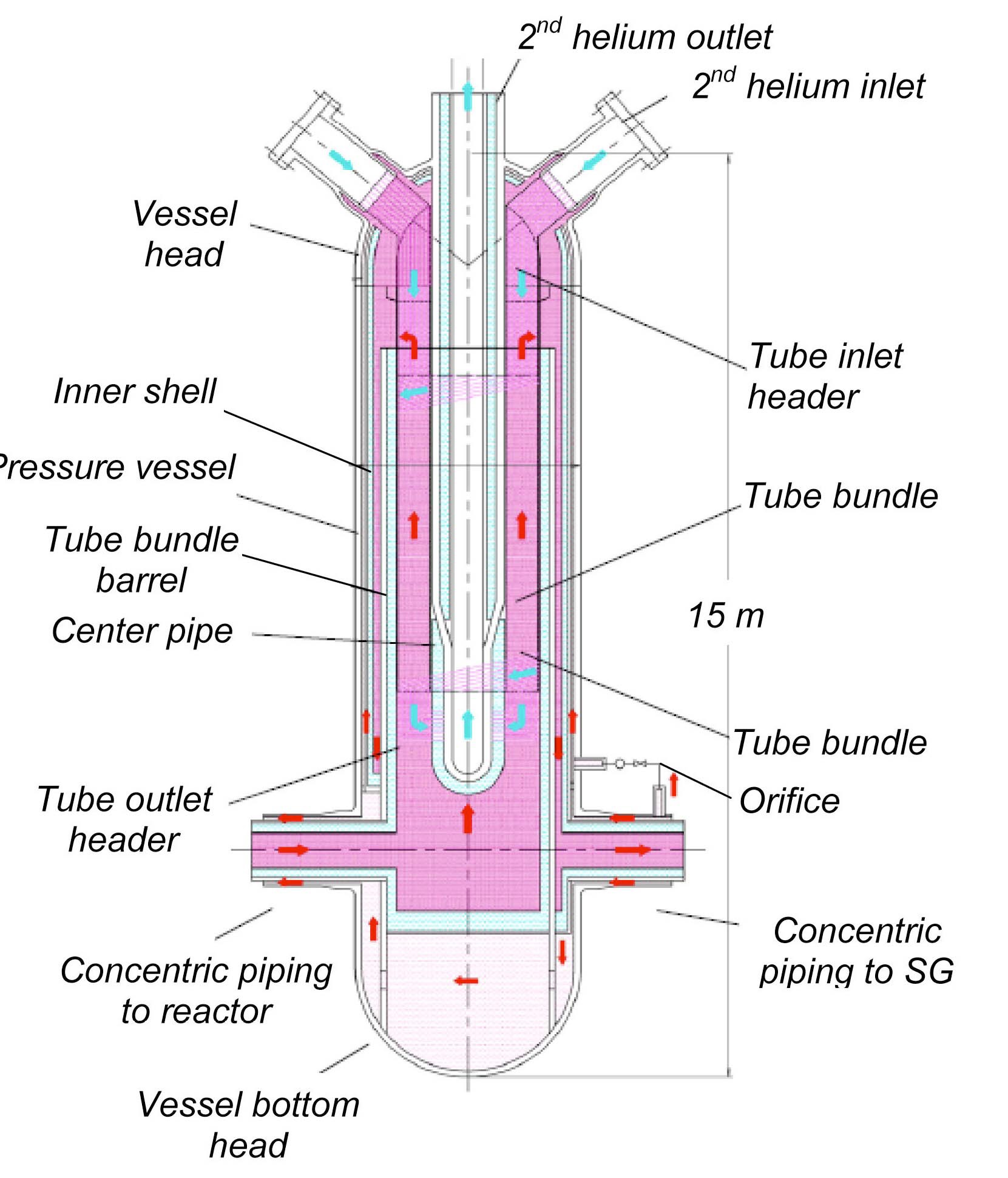
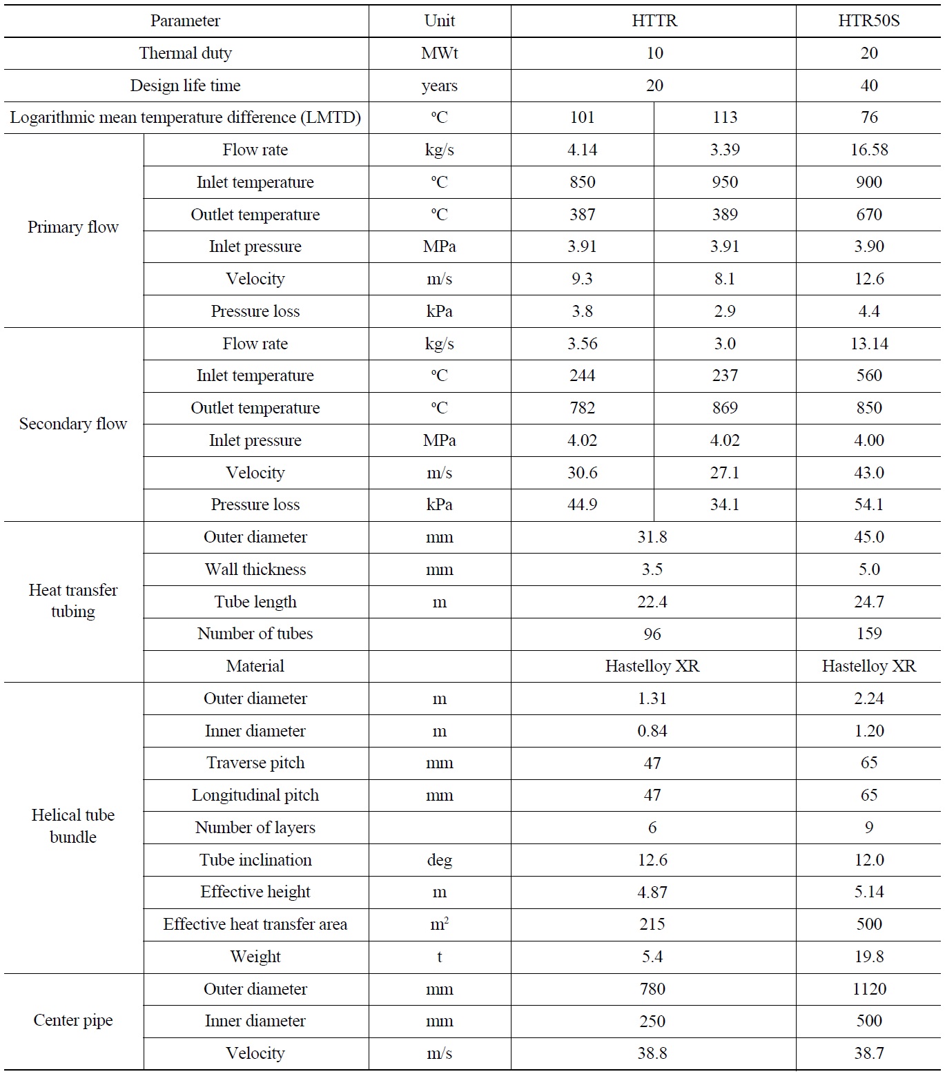
The 20 MWt helical-coiled tube and shell heat exchanger design shown in Figure 7 is a scaled down model of the 170 MWt IHX of the GTHTR300C, though the tube diameter is not changed from the GTHTR300C. Its tube bundle design follows that of the HTTR IHX with the exception of tube diameter. Table 3.1 compares design details of the HTR50S and HTTR tube bundles. The key technologies involved in the HTR50S IHX design are the flow path, tube bundle and pressure vessel as described below.
3.3.1 Flow Path
The flow path is designed to provide pressure vessel cooling, which is to be described in Section 3.3.3, and to ferry three helium flows through the IHX via the leveled pair of the concentric duct nozzles near the bottom of the IHX pressure vessel.
The 900℃ helium from the reactor enters the IHX through the bottom left-hand inner piping, turns to flow upward through the shell side of the tube bundle. Exiting the bundle at 670℃, helium turns 180 degree to flow in an annular downcomer between the tube bundle barrel and inner shell and exits the IHX via the bottom right-hand inner piping. This helium is guided to the steam generator and then returned by the gas circulator to the IHX at 325℃. The temperature is low enough for the helium to sweep the primary pressure boundary uninsulated, still leaving a margin from the vessel temperature limit of 371℃. As a result, the 325℃ helium is routed into the IHX vessel via the outer annulus of the right-hand nozzle and fills the lower vessel space and then exits the IHX vessel through the outer annulus of the left-hand nozzle. This cold helium, which is intrinsically at the highest pressure in the primary coolant circuit at an immediate discharge of the gas circulator, securely envelopes the hot helium in the central tube bundle and protects the pressure vessel even if a leak occurs in the inner shell or pipes.
3.3.2 Tube Bundle
Although the thermal duty of the tube bundle is increased by a factor of two over the IHX of the HTTR, similar design conditions and techniques for thermal sizing are followed as given in Table 2. The bundle is build up of multiple concentric columns of helically-coiled tubes. The metallic plates are inserted between the columns to augment the overall heat transfer by enabling heat radiation between the plates and tubes at the high temperatures. In principle, the radiation effect increases with temperature. Indeed, a strong effect had been experimentally confirmed such that this design feature was built into the HTTR IHX. The primary helium flows in the shell side and the secondary helium inside the tubes. The tubing material is Ni--superalloy of Hastelloy XR that is developed in JAEA specifically for this type of helium-to-helium heat transfer tubing with allowable operating temperature of 950℃. A welding method is developed between this alloy and low alloy tube headers. Tube support structures tolerant of thermal expansion are used.
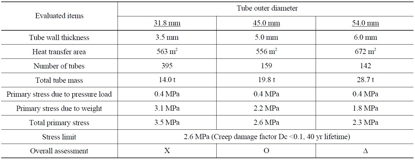
Three heat transfer tube diameters are examined as identified in Table 3. The 31.8 mm tubing is the one used in the HTTR. The other two tubing dimensions, 45.0 mm and 54.0 mm, are determined by fixing the ratio of outer diameter to wall thickness to a value dictated by buckling strength. The thermal design identified that the minimum heat transfer area is obtained with the outer diameter of 45.0 mm. Relative to this diameter, the 54.0 mm diameter is less favorable because its heat transfer area and alloy use are greater and consequently its construction cost is expected to be higher.
Having sized heat exchanger tubes, their primary stress is evaluated. The heat transfer tube is exposed to 900℃ helium gas that makes the creep strength of the material quite low. Unless the pressure between the primary and secondary helium is essentially balanced, the creep damage resulting from the primary stress due to the pressure load could accelerate and quickly exceed the material allowance. In the IHX design, the pressure difference is kept lower than 0.1MPa by a differential pressure control system following the practice in the HTTR. This system enables the HTTR to maintain the primary stress below its maximum limit. The other major contributor to primary stress comes from the unsupported weight of tube itself at the connection to the hot header at the lower end of the tube bundle where
[Table 2.] Intermediate Heat Exchanger (IHX) Thermal Designs
Intermediate Heat Exchanger (IHX) Thermal Designs
the tubes are also exposed to the highest operating temperature. Table 3 identifies that the estimated stress caused by the weight is the major source of the primary stress. With the design criteria of creep damage to be less than 0.1, the total primary stress with the 31.8 mm well exceeds the limit for a 40 year design life time. The outer diameter of 45.0 mm is selected since it best meets both thermal and structural design requirements.
[Table 3.] Sensitivity of Thermal and Structural Design to Selected Tube Diameters

Sensitivity of Thermal and Structural Design to Selected Tube Diameters
3.3.3 Pressure Vessel
The tube bundle is placed in a tube bundle barrel identified in Figure 7. The hottest primary helium of up to 900℃ is thus contained inside this barrel, whose inner wall surface is insulated. On the other hand, the inner shell that is also internally insulated contains helium flow of up to 670℃. The annulus between the inner shell and the pressure vessel is a conduit of helium at 325℃ used to cool the pressure vessel. This cooling helium is bypassed off the core inlet flow through the fixed orifice line and its flow rate is about 1% of the main coolant flow. The orifice is used to measure the bypass flow rate, which is then subtracted from the main circulator flow rate to give the actual reactor coolant flow rate. The reactor coolant flow rate generally needs to be known during operation. For this reason, a similar bypass flow measurement system is operated around the IHX of the HTTR.
The cooling helium for the pressure vessel is recirculated through the gaps at the tube header penetrations in the inner shell at the top of the IHX. The cooling helium is intrinsically circulated under the positive pressure difference from the outside to the inside of the inner shell. This 20 kPa pressure difference results from the sum of the pressure drops of all reactor coolant flow paths. Precise control of the cooling flow is not necessary since it does not affect reactor power operation. When desired, however, its flow rate can be adjusted in the orifice line during commissioning and subsequent operation of the plant.
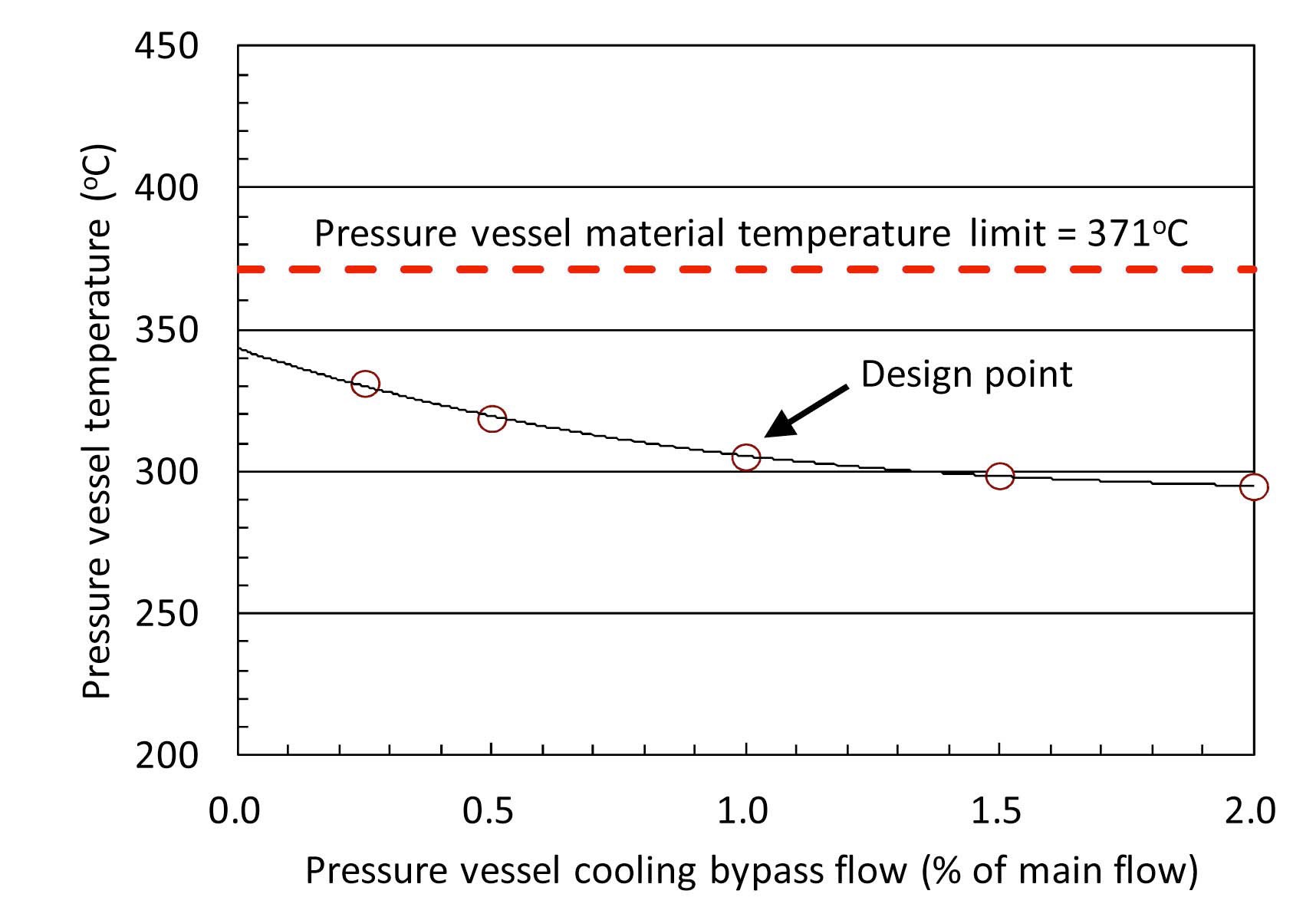
Figure 8 shows the sensitivity of the IHX pressure vessel temperature to the cooling bypass flow rate. The thermal insulator is applied on the vessel external surface for the purpose of limiting parasite heat loss to the air surrounding the pressure vessel. The resulting equivalent transfer coefficient is assumed to be 4.56 W/m2 K, which corresponds to the operational measurement of the HTTR
IHX thermal insulator. As shown in Figure 8, the maximum pressure vessel temperature is 305℃ at the design point of 1% bypass cooling flow in the annulus between the pressure vessel and the inner shell. Once again, precise control of the bypass cooling flow rate is unnecessary since the temperature of the pressure vessel is kept at acceptable margin, saying 50℃, below its material temperature limit over a wide range of the cooling flow, as seen in Figure 8.
This section describe the multiple applications to be implemented in three phases, of which the production parameters are specified in Table 1.
4.1 Phase I ? Base commercial Applications
During Phase I, HTR50S will operate at 750℃ core outlet temperature. The balance of plant operates on a Rankine cycle with steam extraction for cogeneration of steam and district heating.
4.1.1 Power Generation
Superheated steam at 538℃ and 12.5 MPa is produced in the SG and sent to the steam turbine. The steam turbine is a non-reheat and three stages regeneration cycle. The three-stage steam extraction from the turbine to a deaerator and two high pressure feedwater heaters produces a final feedwater temperature of 200℃ at the SG inlet. The gross electricity generated is 17.2 MWe and the generation efficiency is 34% in this system.
4.1.2 Cogeneration of District heating
The steam at 161℃ and 0.4 MPa is extracted from a turbine mid stage and flows through a heat exchanger, in which the steam is condensed to 95℃ while transferring the heat to the circulating water of the district heating network. The district heating network is rated at 25 MWt with outflow water at 95℃ and return flow at 70℃. The network meets heating and hot water supply requirement for about 8,000 people. Due to steam extraction, the turbine electricity generation is reduced to 13.5 MWe at the generation efficiency of 27%. The power to district heat cogeneration ratio is adjustable. The overall nuclear reactor thermal power utilization is 77%.
4.1.3 Cogeneration of Process Heat
The steam of 400℃ and 4.5 MPa is extracted from a mid stage of the turbine and guided to a 25 MWt steam converter to produce process steam of 44.6 t/h at 310℃ and 10.5 MPa. The steam condensate of 200℃ is directly used as feedwater to the SG inlet. While cogenerating process steam, the turbine electricity generation reduces to 10.5 MWe and electricity generation efficiency is 21%. The overall nuclear reactor thermal power utilization is 71%. Alternatively, the steam of 533℃ and 12.0MPa may be extracted from the inlet of the turbine. In this case, the turbine electricity generation is further reduced to 8.6 MWe with power generation efficiency of 17%. The heat utilization efficiency is estimated to be 67%.
4.2 Phase II ? Demonstrating Gas Turbine Applications
Operation will be performed to validate the performance characteristics of the GTHTR300 series, in particular, the serial operation of the IHX, the gas turbine control operations including loss of load and inherent surge protection, and the cogeneration using reactor waste heat.
4.2.1 High Temperature Process Heat
For heat cogeneration by the GTHTR300C shown in Figure 3, the IHX is serially arranged at the upstream of the gas turbine. To demonstrate this cogeneration arrangement in the HTR50S, the SG is used to replace the gas turbine of the GTHTR300C to operate in series with the IHX. The advantage of the serial over parallel operation is as follows:
1) It provides a once-through single-pass for primary flow circulation, minimizing the number of circulators required and the complexity of piping.
2) It yields a larger LMTD (logarithmic mean temperature difference) in the IHX to obtain compact heat exchanger surface to minimize the cost of this high specific cost superalloy equipment.
3) It increases quality of process heat supply, in particular being able to accommodate the 500℃ or higher secondary inlet temperature of helium required to couple with the IS-process.
In serial operation, the primary helium enters the shell side of the IHX at 900℃, transfers 20 MWt heat to the secondary helium in the tube bundle, and exits the IHX at 670℃. The secondary helium enters the tube side of the IHX at 560℃ and exits it at 850℃. The LMTD is 76℃. The secondary pressure is controlled higher, but only marginally without unduly stressing the high temperature tubes, than the primary pressure by a dedicate pressure balance system. The pressure difference is intended to prevent out leak of radioactive material from the primary system in case of accidental leak in the IHX tubes.
Although with the IHX installed, the single operation of the SG is still permitted at full thermal power of 50 MWt. In this case, the reactor outlet temperature is returned to 750℃. The primary helium flows through the IHX without exchanging heat with the secondary circuit such that the inlet temperature of helium to the SG equals to the reactor outlet at 750℃. The secondary circuit is maintained at pressure by the above-mentioned pressure balance system but without the forced circulation of flow through the tubes. The thermal stress in the IHX tubes is expected minimum because the tubes are exposed to uniform and low-end operating temperatures in the single operation mode.
The heat rate to the IHX can be varied according to variable cogeneration control method reported for the GTHTR300C [33,34]. The principle of the method is use of flow bypass for the reactor and IHX while keeping all temperature conditions unchanged in the reactor, IHX and SG. The variable cogeneration may be tested in the HTR50S by applying an adjustable heat sink, other than the gas turbine, to the IHX secondary side.
4.2.2. Power Generation
While open cycle air gas turbines are widely employed in fossil-fired power plant, the closed cycle helium gas turbine is required in the most efficient and economical way of generating nuclear power as shown in the design of the GTHTR300 series. JAEA has developed the helium compressor and magnetic bearing which are uniquely required to construct the helium gas turbine. To operate the gas turbine in the HTGR primary circuit as in the GTHTR300, however, two feasibility conditions remain to be clarified that the reactor primary helium coolant is not so radioactive that it contaminates the gas turbine to the extent that its maintenance becomes difficult and that the control operation of the gas turbine is acceptable not to jeopardize the nuclear plant safety. The latter is concerned with specific methods of control such as variable inlet pressure but constant heat input as well as flow bypass [33,35], which differ from the well-understood control practice of open cycle gas turbine.
Fortunately the above two conditions may be tested separately using the HTGR50S. The first condition can be verified by placing blade specimen in the HTR50S primary circuit at 900℃ reactor outlet and high burnup fuel during an operating period. The specimen can be removed during refueling and the activity deposited on it be measured to develop methods of maintenance access and service. The second condition will be tested by the present gas turbine operated in the IHX secondary loop of the HTR50S. Since the secondary circuit is free of contamination, the gas turbine can be readily accessed and serviced as expected for the first-of-a-kind demonstration system.
The most important issue for operation safety of the gas turbine is to secure surge margin in case of forced transients such as a loss of load. In open cycle, the compressor operates on the principle of constant atmospheric inlet temperature and pressure. Furthermore the inlet and outlet of the compressor are not linked. The surge margin is typically controlled by varying the flow angle of the inlet guide vanes of the compressor. In closed cycle, the compressor inlet conditions are variable and they are aerodynamically and thermodynamically coupled to the compressor outlet through the turbine and the various other components of the cycle. The dynamic characteristics of the surge margin of the close cycle are expected to differ from those of the open cycle and will be investigated in the operation of the HTR50S.
Referring to the section of the gas turbine cycle process of the HTR50S in Figure 5, the hot helium heated in the IHX to 850℃ is guided to the gas turbine for expansion to convert thermal energy into shaft power needed to drive an electric generator for power generation of 6.9 MWe. The efficiency is 34.5%, lower than the 45.5% of the GTHTR300, in part because of the small hardware rating and in other part because the recuperator is not optimized for efficiency in the present plant. The turbine exhaust helium enters the recuperator, wherein a part of residual heat is recovered to preheat the returning helium to the IHX to 560℃. Having finally been cooled to the cycle bottom temperature by rejecting waste heat in the precooler, the helium is compressed in the gas turbine compressor, preheated in the recuperator and heated finally in the IHX to the cycle maximum temperature of the cycle process.
4.2.3 Cogeneration of District Heating
Heat cogeneration with steam turbine is only possible by extracting live steam from the turbine. A loss of steam turbine power generation is thus inevitable as described earlier for the Phase I steam turbine plant. The loss is avoided in the gas turbine plant, where waste heat from the precooler is fully applicable to such low-temperature application as district heating [36].
The gas turbine power conversion cycle of the HTR50S rejects sensible waste heat of 12.2 MWt in a temperature range of 205 to 28℃. The waste heat is removed in the precooler by a closed water loop. The water is heated to 160℃ at 0.8MPa. This water enters another district-heating heat exchanger to transfer 7.6 MWt heat to the district network with outflow hot water at 95℃. The balance of the waste heat is removed in a cooling heat exchanger. The water returns to the precooler at 22℃. The cogeneration of district heat raise the overall reactor thermal power utilization of the gas turbine plant to 72.5% without penalizing the power generation, which remains constant at 34.5%.
4.3 Phase III ? Hydrogen Production
The production parameters are preliminarily scaled from the 170 MWt IS-process hydrogen plant design of the GTHTR300C [24]. The hydrogen plant is operated in series at the upstream of the gas turbine following the GTHTR300C cogeneration process arrangement. About 5.7 MWt of the 20 MWt IHX heat supply is input to the hydrogen plant and the remainder is used for gas turbine power generation. The maximum temperature of the ISprocess is 800℃, as opposed to the 850℃ of the GTHTR 300C. The hydrogen production rate of the HTR50S is estimated to be 800 Nm3/h..
The HTR50S design study demonstrates that the small modular HTGR system can be considered for a range of electrical and industrial applications and that such system is deployable in the near term. None of the critical technologies built into the base HTR50S design requires significant extrapolation of the HTTR database and licensing requirements. The fuel and pressure vessel are used without design changes. The core power density is increased but the fuel is operated within the same temperature limit. The balance of plant is an off-the-shelf Rankine cycle power generation plant with provision of steam extraction for steam supply and district heating. The base plant may be upgraded for higher temperature operation using the advanced fuel with improved fuel cycle economics and to accommodate demonstration of additional applications. These include high temperature heat supply by the IHX, which is twice the scale of the IHX operated in the HTTR, efficient power and heat cogeneration by the gas turbine whose components have been developed in larger scales for the GTHTR300, and nuclear hydrogen production coupled with the ISprocess.
By virtue of its readiness for near-term commercialization and its potential for longer term performance upgrade and application expansion, the small modular reactor HTR50S is expected to play its role as adaptable energy source to distributed and industrial applications worldwide. In particular, developing countries may jump-start introduction of advanced and safer nuclear energy systems by “importing” the base HTR50S reactor by up-scaling the existing HTTR by a factor of less than 2, installing it widely as a standard heat and power cogeneration system, and then developing it for the other advanced applications when needed.