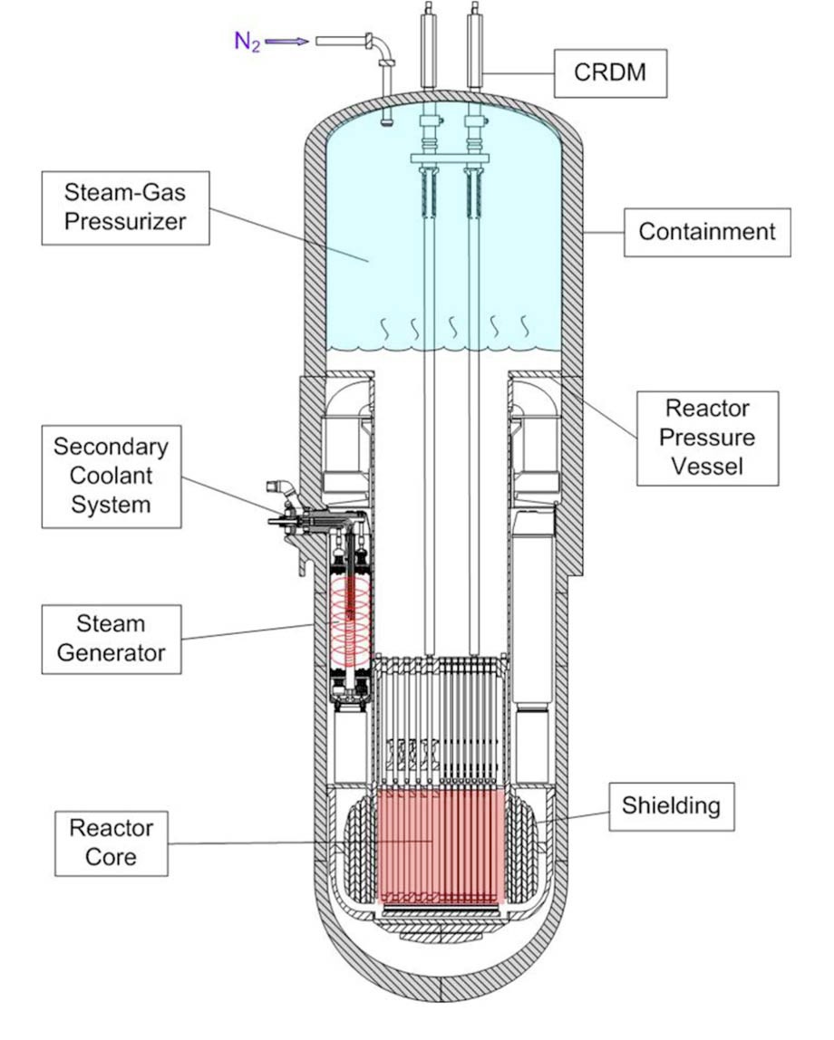
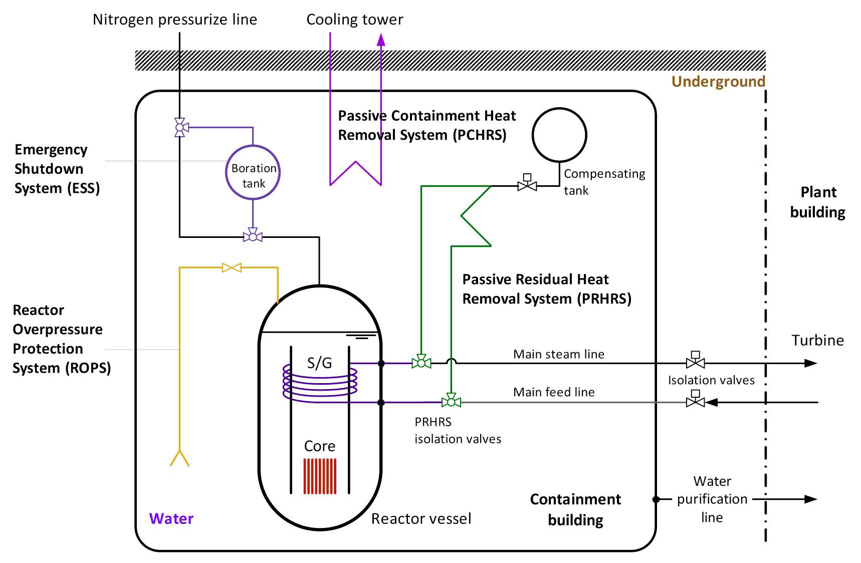
Remarkable efforts to deploy small modular reactors (SMRs) as an advanced energy source have been recognized globally. Most SMRs employ an integral layout of the primary system since the potential risk arising from a largebreak loss-of-coolant-accident (LBLOCA) can be eliminated due to the absence of large-diameter pipelines. Among the various types of SMR, REX-10 is a small-sized integral PWR designed by Seoul National University (SNU) in order to supply small-scale electricity and nuclear district heating [1]. REX-10, possessing the capability to generate 10MWth output, can be defined as a fully-passive integral PWR in which the coolant flow is driven by natural circulation. Two other distinct features of REX-10 are that the pressure of the system is maintained by a built-in steamgas pressurizer, and the decay heat is removed by a passive residual heat removal system (PRHRS) after reactor shutdown. The schematic diagram of REX-10 is depicted in Fig. 1.
To investigate the thermal-hydraulic behavior and the safety performance of a specific reactor during transient
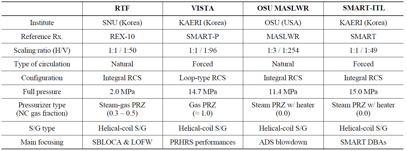
and accidental situations, a series of integral effect tests (IET) has to be performed. For conventional loop-type reactors, tens of IETs have been conducted internationally, including LOFT [2], BETHSY [3], Semiscale [4], and so on. A few integral test facilities such as PKL-III, ROSA /LSTF, and PACTEL are still active [5]. On the other hand, an experimental program for an integral PWR is quite uncommon; VISTA [6] and OSU MASLWR [7] are the only IET facilities of an integral PWR ever constructed and tested. Although KAERI and B&W are building largescale integral test facilities named SMART-ITL [8] and IST, respectively, the main testing programs are yet to begin. The features of the IET facilities built for an integral PWR are summarized in Table 1.
It should be noted that both VISTA and OSU MASLWR are equipped with active systems which run even under normal operation conditions. VISTA utilizes the reactor coolant pump (RCP) to induce forced convection of the coolant, and OSU MASLWR regulates the system pressure by controlling the heaters in the pressurizer. These active systems explain why the data from previous IETs cannot be used to verify the safety performance of an integral PWR operating in a passive manner such as REX-10. To confirm the safety aspects of REX-10 during the postulated accidents, a thermal-hydraulic testing program in a scaled model that reflects the distinct design features of REX-10 is required.
In this study, the integral effect tests on two design basis accidents (DBAs) are carried out in a scaled-down test rig named RTF: SBLOCA, initiated by the rupture of a 1/4 inch diameter pipeline connected to the pressurizer vessel, and LOFW, simulated by the termination of the feedwater supply into the helical-coil steam generator. The RTF is a scaled apparatus of REX-10. The height ratio is maintained and the volume and the power are reduced by 1/50. The current RTF has been altered from the previous model [9] so that the performance of the steam-gas pressurizer
[Table 1.] Features of IET Facilities for Integral PWRs

Features of IET Facilities for Integral PWRs
can be simulated. Both the steady-state characteristics and the major thermal-hydraulic parameters during SBLOCA and LOFW accidents are presented in this paper. The experimental results from the testing program are used to evaluate the transient RCS responses and to assess the safety aspects of REX-10 during the postulated DBAs. In particular, the transient pressurization of the RTF in response to the LOFW accident is experimented with two types of pressurizers, the steam-gas pressurizer and the steam pressurizer, and the relative performances are compared.
A brief description of the REX-10 is given in Sec. 2. Details of the RTF apparatus as well as the experimental procedure are described in Sec. 3. The analysis and discussion on the experimental results are presented in Sec. 4.
The REX-10 development program is intended to achieve more stable, efficient, area-independent system operation and energy production [1]. The design goals of REX-10 include implementing high levels of inherent safety into the reactor design to enhance public acceptance for an innovative nuclear system, and attaining non-proliferation during the construction and operation period. It can be utilized to provide small-scale electricity generation and nuclear district heating either in the vicinity of densely populated cities or in remote areas far from power grids. The configuration of the REX-10 reactor system is shown in Fig. 2.
REX-10 is an integral PWR which contains the primary components inside the reactor pressure vessel (RPV). This layout substantially reduces the potential break points in the primary circuit and makes the reactor system more compact. The height of the reactor pressure vessel is 5.715m. REX-10 is designed to operate at the low system pressure of 2.0 MPa and its coolant flow is driven by natural circulation
without a RCP. In the core, the 9×9 heterogeneous Th/UO2 fuel assemblies generate a thermal power of 10 MW. The long riser region above the core provides sufficient head for natural circulation of the coolant.
The steam-gas pressurizer located at the upper part of the RPV is the most distinguishing component of REX-10. The steam-gas pressurizer is equipped with no active system; instead of controlling the heater or spray, it pursues passive operation by containing a certain amount of non-condensable gas in the gaseous mixture. The once-through steam generator of REX-10 consists of helical tubes wrapped around the entire annulus between the core barrel and the RPV. As shown in Fig. 2, the containment of REX-10 is filled with water and buried underground. As a representative safety system of REX-10, the PRHRS removes the decay heat in the event of reactor shutdown. The PRHRS is automatically put into action by a trip signal. Then it condenses vapor from the steam generator by means of natural circulation through a heat exchanger, which is located higher than the S/G and submerged in the water of the containment.
In short, REX-10 is a fully-passive integral PWR which maximizes the passive performance of a reactor under normal operation as well as accidental conditions. See Ref. [1] for more details on the description of the reactor system and the major design parameters of REX-10.
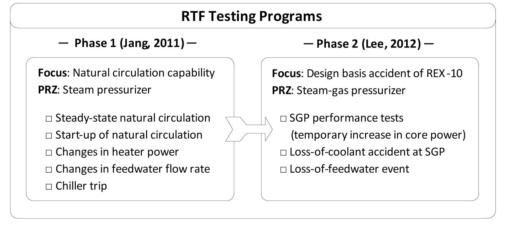
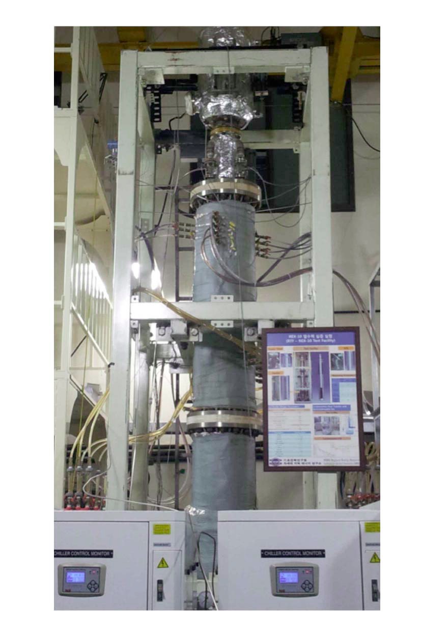
The RTF is a scaled model of REX-10 that is designed to experimentally evaluate the characteristics of natural circulation under the steady-state condition [10] and investigate the thermal-hydraulic system responses during hypothetical accidents. Figure 3 shows a photographic view of the RTF apparatus. The testing programs of the RTF are divided into two phases as described in Fig. 4. Phase 1 focused on investigating the natural circulation capability of REX-10. Mainly conducted by Jang et al. [9,10], the experiments of Phase 1 include the steady-state natural circulation tests, the mild transients initiated by the changes
in the heater power or feedwater flow rate, and the chiller trip event. It is noted that, in Phase 1, the RTF was not equipped with the steam-gas pressurizer as in REX-10. As the main concern of Phase 1 was the natural circulation characteristics in an integral reactor system, the pressure transient affected by the performance of the steam-gas pressurizer was not of interest.
On the other hand, Phase 2 evaluates the transient RCS responses and the safety performance of REX-10 during the postulated accidents. The steam-gas pressurizer module and the relevant instrumentation are installed in Phase 2. Besides a couple of preliminary performance tests on the steam-gas pressurizer, the DBAs of a fully-passive integral PWR including SBLOCA and LOFW are experimentally investigated. In what follows, the details of scaling, test facility, and experimental procedure for the RTF apparatus are described.
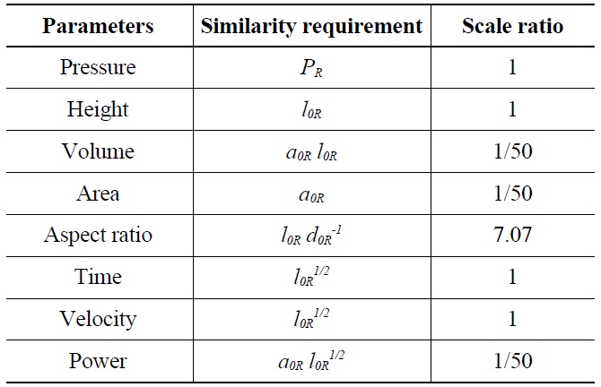
As the testing program of the RTF includes rapid system depressurization, accompanied by two-phase phenomena, the two-phase similarity law has to be taken into account. Thus, when designing the RTF, the scaling method proposed by Kocamustafaogullari and Ishii [11] was used to determine the major design parameters for the RTF. Table 2 lists the major scaling factors of the RTF.
The homologous relationship between the RTF and REX-10 is determined from the constraints on available space and power. Since the top priority of the RTF is system operation under natural circulation condition, the height ratio was maintained in the scaled facility in order to provide an identical hydrostatic head to that of REX-10 for natural circulation. In addition, due to the relatively low system pressure of REX-10, the test facility can easily achieve full pressure. The volume scale ratio was set to 1/50. Then from the basic principles of geometric, kinematic, dynamic, and energy density similarity, the scale ratios for area (1/50), time (1), velocity (1), and power (1/50) were determined as shown in Table 2. In short, the RTF is a full-height fullpressure facility with reduced power.
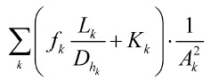
It should be noted that local components of the RTF are not strictly scaled using a systematic scaling approach. In fact, the most significant scaling distortion of the RTF is the violation of the dynamic similarity over the entire loop. In a natural circulation system, the following requirement has to be fundamentally satisfied for dynamic similarity as:
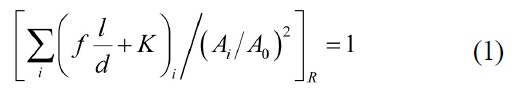
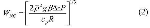
Generally, this criterion can be met by using appropriate orifices to provide the flow restriction and the increased frictional losses. In the RTF, however, too much flow resistance is introduced at a local channel prepared for flow measurement (details are presented in the next section). To quantitatively evaluate the scaling distortion of the dynamic similarity expressed in Eq. (1), the loop resistance can be indirectly estimated using the steady-state experimental results and the analytical solution for the natural circulation flow rate expressed as:
[Table 2.] Major Scaling Factors of RTF
Major Scaling Factors of RTF
This approach reveals that the resulting ratio of Eq. (1) between the RTF and REX-10 is about 22.5. Therefore, a far lower natural circulation flow is established than the prescribed scale value in the RTF.
As mentioned before, a SBLOCA initiated by the rupture of a 1/4 inch diameter pipeline is simulated in this study. Since the detailed design of the nitrogen injection line of REX-10 is not fulfilled, the break size of the SBLOCA test is chosen arbitrarily. Therefore, the homologous relationship between the 1/4 inch diameter break in the RTF and the prototypical SBLOCA in REX-10 has to be specified. The similarity criterion for the break size derived from the mass inventory and boundary flow scaling [12] is expressed as:
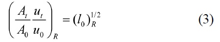
In the case of choking, the break flow velocity depends on the local pressure ratio across the discharge point. Since the RTF maintains prototypic pressure, the fluid velocity of choked flow is the same in the RTF as in the prototypical REX-10 ((
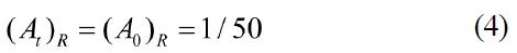
In short, the throat area ratio between the RTF and REX-10 is equal to the flow area scale ratio since the pressure and the length are preserved in the RTF. A 1/4 inch pipe rupture in the RTF is equivalent to the break of a 1.8 inch gas connecting pipe in REX-10.
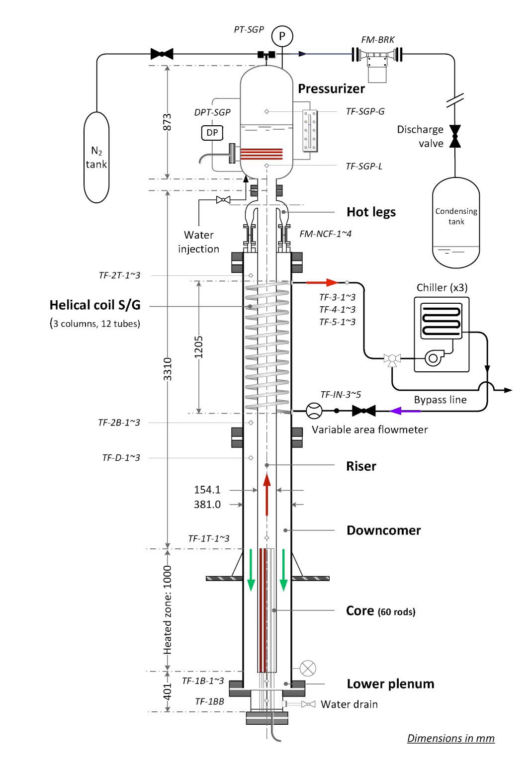
The RTF models all system components of REX-10 housed in the RPV. The primary circuit of the RTF consists of electrical heaters, a riser, four hot legs, and a helical-coil heat exchanger. It is designed to operate at full pressure (2.0 MPa) and temperature (200 ℃) with a maximum heater power of 200 kW. The reactor vessel, which is 5.71 m in height including the steam-gas pressurizer vessel, is made of type 304 stainless steel and its wall thickness is decided on the basis of ASME Boiler and Pressure Vessel Code section III [13] to withstand the high pressure condition.
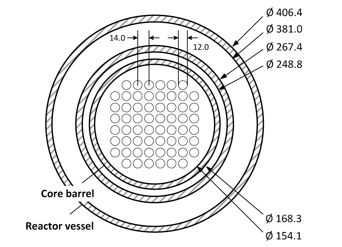
Figure 5 illustrates the integral configuration of the primary system in the RTF. The core region consists of 60 electrical heaters arranged in a square array. The pitch-todiameter ratio of the heater rods is 1.167 and the effective heated length is 1.0 m. The core cross sectional view is depicted in Fig. 6. The primary coolant, heated in the core, passes the long riser and flows into the annular space through four hot legs. Unlike in REX-10, these elbowshaped hot legs are built to install the flowmeters to measure the natural circulation flow rate. Due to these auxiliary structures and equipment, enormous flow resistance is applied to the fluid as the coolant passes through a very narrow path. The minimum diameter of the transverse plane inside the flowmeter is at most 9 mm. Consequently, this region causes major distortion in the dynamic similarity between the RTF and REX-10 as discussed in Sec. 3.1.
The once-through heat exchanger, with an active length of 1.205 m, comprises twelve helical tubes arranged into 3 columns. Each coil is 7.746 mm in inner diameter, 9.525 mm in outer diameter, and approximately 4.38 m in length. The innermost, intermediate, and outermost columns are composed of 3, 4, and 5 helical tubes, respectively. The helical coils wrap around the entire annulus between the core barrel and the RPV wall. The primary coolant flows downward across the tube bundles and transfers heat to the secondary coolant flowing inside the tubes. The lower plenum is located at the lowest region of the RTF. Most instrumentation around the core is inserted from the bottom through the lower plenum.
As aforementioned, in Phase 1 of the RTF testing program previously performed by Jang et al. [9,10], the steamgas pressurizer was not employed in the apparatus since the experiments were planned primarily to estimate the natural circulation capability of the prototypical REX-10. Instead, a convectional steam pressurizer was utilized at
that stage. The pressurizer vessel was connected to the top of the RTF through a long, narrow pipe. In addition, the non-condensable gas was not inserted in the gas region. The system pressure was regulated by controlling the internal
electrical heater installed inside the pressurizer vessel to evaporate water. In this case, the RCS and the pressurizer are almost not interacting and the performance of the steamgas pressurizer in the presence of non-condensable gas cannot be examined.
Thus, in Phase 2, the pressurizer module is placed directly on the top of the RTF so that the function of the steamgas pressurizer can be simulated [14]. A couple of instrumentations are also employed in the steam-gas pressurizer, and the nitrogen injection line and the gas vent line, branched off by a union tee, are linked to the upper side of the pressurizer vessel for regulation of the fluid inside. The vent line provides the gaseous mixture with passage to a condensing tank when breaking the pressure boundary in the SBLOCA experiment or depressurizing the RTF system after the experiment is finished. The cylindrical vessel of 0.381 m in diameter and 0.873 m in height is heavily insulated. The effective pressurizer region may be regarded as the whole volume above the uppermost elevation of the hot legs. For visualization of the water level in the pressurizer, a small rectangular chamber with a transparent window pane on one side of the wall is installed.
In the RTF, the helical tubes of the steam generator form a closed loop with three air-cooled type chillers as a secondary circuit. The secondary feedwater from the chillers, at atmospheric pressure, enters the helical tubes and flows up. The coolant is heated up passing through the heat transfer region and flows back into the chillers. Each chiller recirculates the water through the tubes of a specific column, and the coolant is split into the coils at the water distributor.
While the feedwater turns into saturated steam when leaving the coils in REX-10, the secondary coolant is maintained in the subcooled state in whole channels in this experiment by setting up the proper mass flow rate. The flow rate of each helical coil is controllable by a ball valve located ahead of the tube entrance. When the cooling capability of a chiller is not sufficient to keep the feedwater temperature constant, a portion of hot water from the helical tubes can be drained before returning to the chiller while continuously supplying tap water to the reservoir of the chiller.
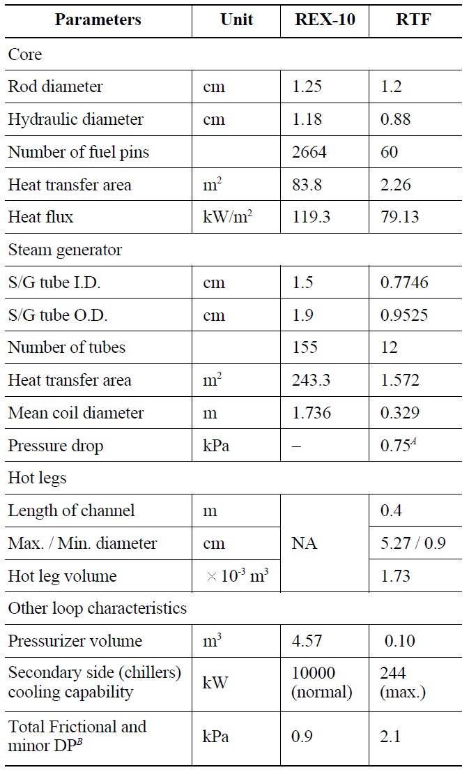
To provide relevant information needed to assess the code capability as thoroughly as possible, technical specifications of the RTF associated with loop characteristics are clarified in Table 3. From table 3, one can not only compare the system parameters of the RTF and REX-10, but also obtain most requisite information for code application to the RTF. Note that the total frictional and minor loss in the RTF, estimated using Eq. (2), is about 2.1 kPa when the flow rate in the primary system is 0.424 kg/s.
Major subsections of the RTF are instrumented so that system parameters can be measured and recorded during the experiments. The measurement instrumentation is depicted in Fig. 5. In the RTF, a total of 32 K-type thermocouples are used to acquire the temperature data at various positions of the primary and secondary circuits. For the primary system inside the reactor vessel, the inlet and outlet temperatures of the core and the steam generator, as well as the temperatures at the downcomer and the lower plenum, are measured. In particular, three thermocouple sensors are employed at both the core inlet and outlet to get the mean temperature of the channel. Two thermocouples are installed at the steam-gas pressurizer vessel to measure the liquid and gas region temperatures. The feedwater inlet temperatures of each tube column and outlet temperatures of each helical coil are also measured.
The mass flow rate by natural circulation is measured using the turbine flowmeters installed at the hot legs. The feedwater flow rate into a helical coil is measured by the variable-area flowmeters, but not recorded by the data acquisition system. Besides the pressure gauge, a pressure transmitter is installed at the top of the pressurizer vessel
[Table 3.] Detailed Specifications of the RTF Apparatus

Detailed Specifications of the RTF Apparatus
in order to measure the total pressure of the system. The water level in the pressurizer is measured by a differential pressure transmitter.
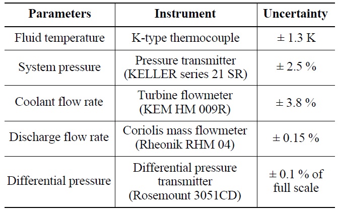
During the fluid discharge in the SBLOCA experiment, the composition of the gaseous mixture out of the pressurizer vessel will definitely change continuously with time. Thus general flowmeters measuring the volumetric flow rate are not applicable to this flow. In this experiment, a Coriolis mass flowmeter is used to measure the discharge rate through the rupture. The 1/4 inch pipeline between the mass flowmeter and the pressurizer vessel is wrapped with electric band heaters and covered with thermal insulation to prevent the variation of gas properties resulting from initial contact along a cold pipe. The measurement instruments and their uncertainties are summarized in Table 4.
[Table 4.] Measurement Instruments and Uncertainties

Measurement Instruments and Uncertainties
[Table 5.] RTF Conditions at Steady-state Before Transient Tests
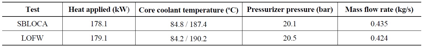
RTF Conditions at Steady-state Before Transient Tests
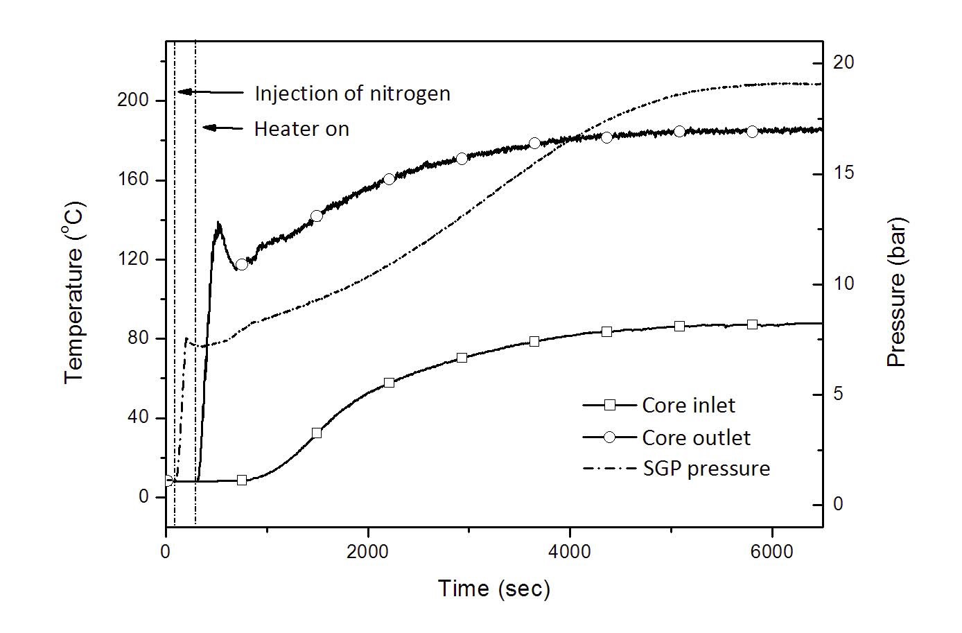
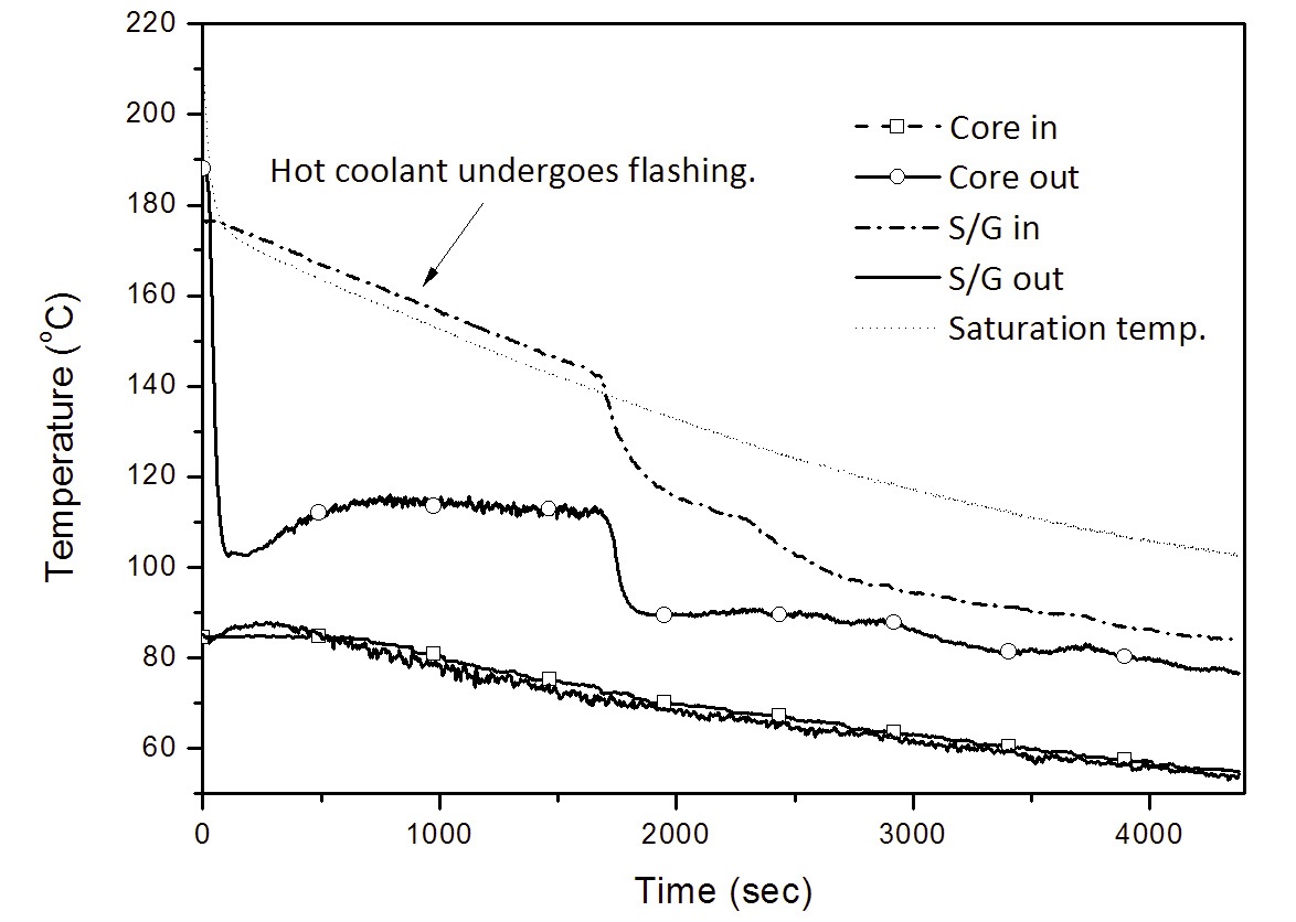
Prior to the initiation of each run in transient experiments, the system has to be brought to the steady-state condition while continuously supplying the core power and at the same time providing feedwater for heat removal. Figure 7 shows a typical thermal transition of the coolant before arriving at the heat balance condition.
At the beginning, the tap water is injected into the RTF so that the pressurizer volume is half filled with water when the system is heated up and reaches the equilibrium state. Then the desired amount of nitrogen gas is injected into the upper volume of the steam-gas pressurizer. Nitrogen injection at the very early phase of the experiments is intended to prevent the boil off of the coolant during heat up. When deciding the amount of nitrogen required, one has to take into account the rise in the partial pressure of the non-condensable gas not only by the increase of the fluid temperature but also by changes in the volume of the gaseous mixture due to the expansion of RCS coolant.
The maximum heater power is applied to the core, and the chillers are operated subsequently. It is noted that about 10% of the total design power is lost due to the failure of a few electric heaters. The coolant temperature and the system pressure gradually increase until heat balance equilibrium is established, i.e. the pressure and the temperature profile of the primary circuit are invariant with time. The temperature of the liquid in the pressurizer also continues to increase as high as possible in this apparatus. The coolant conditions at the steady-state prior to each transient test are summarized in Table 5.
The SBLOCA experiment begins with the opening of a valve located midway between the steam-gas pressurizer and the condensing tank to simulate the rupture of a 1/4 inch diameter pipeline. In the LOFW test, the transient is initiated by turning off all chillers to stop feedwater supply. In REX-10, the high and the low pressurizer pressure trips occur at 2.3 MPa and 1.7 MPa, respectively. When the system pressure of RTF reaches a trip setpoint, the heater power is dropped to the decay heat level (about 7%) and the chillers are turned on again to simulate the actuation of the PRHRS.
Since the PRHRS is neither established in the RTF system nor designed in detail for REX-10, a predetermined flow rate has to be given as a boundary condition for the secondary system of the RTF. Generally, the natural circulation flow rate in the PRHRS trains is influenced by the design of the heat exchanger, the elevation of the cooldown tank above S/G, the flow resistance of the loop, and so on. When determining the PRHRS flow rate in the RTF, the experimental investigation performed at the VISTA facility was reviewed. According to a reference test for the PRHRS operation in VISTA, the maximum natural circulation flow rate was estimated at 9.2% of the normal secondary flow rate [15]. In the RTF tests, a slightly greater margin of flow rate is given so that the natural circulation flow rate of the PRHRS is maintained constant at 1/9 (11%) of the nominal feedwater flow rate.
In this regard, the RTF tests have some limitations in simulating the realistic performance of the PRHRS of REX- 10. The fluid flow in the actual PRHRS loops is driven by the two-phase natural circulation. As the PRHRS is actuated, the steam is generated in the secondary side of S/G and transported to the heat exchanger submerged in the cooldown tank for condensing. The flow rate is gradually decreased as the heat transport in the S/G is reduced. In the RTF experiments, on the other hand, a constant flow is supplied to the S/G by forced convection and the outlet condition of the S/G is rapidly changed into the subcooled state. That is, there is a limit in investigating the heat transfer by the two-phase natural circulation and the variation of the secondary flow rate.
The major objectives of the transient experiments in the RTF are: (a) to investigate comprehensive thermalhydraulic responses of an integral PWR equipped with the steam-gas pressurizer on natural circulation, during accident situations of SBLOCA and LOFW, and (b) to provide the unique data needed to evaluate the prediction capability of a system analysis code such as TAPINS [14]. Figure 7 reveals that an integral reactor system incorporating the steam-gas pressurizer can maintain the stabilized RCS conditions. In this study, both of the DBA tests are initiated while applying the maximum heater power in the fullpressure condition.
4.1 Steady-state Natural Circulation
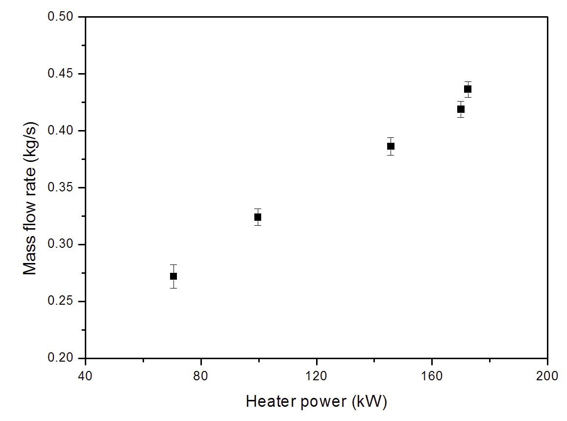
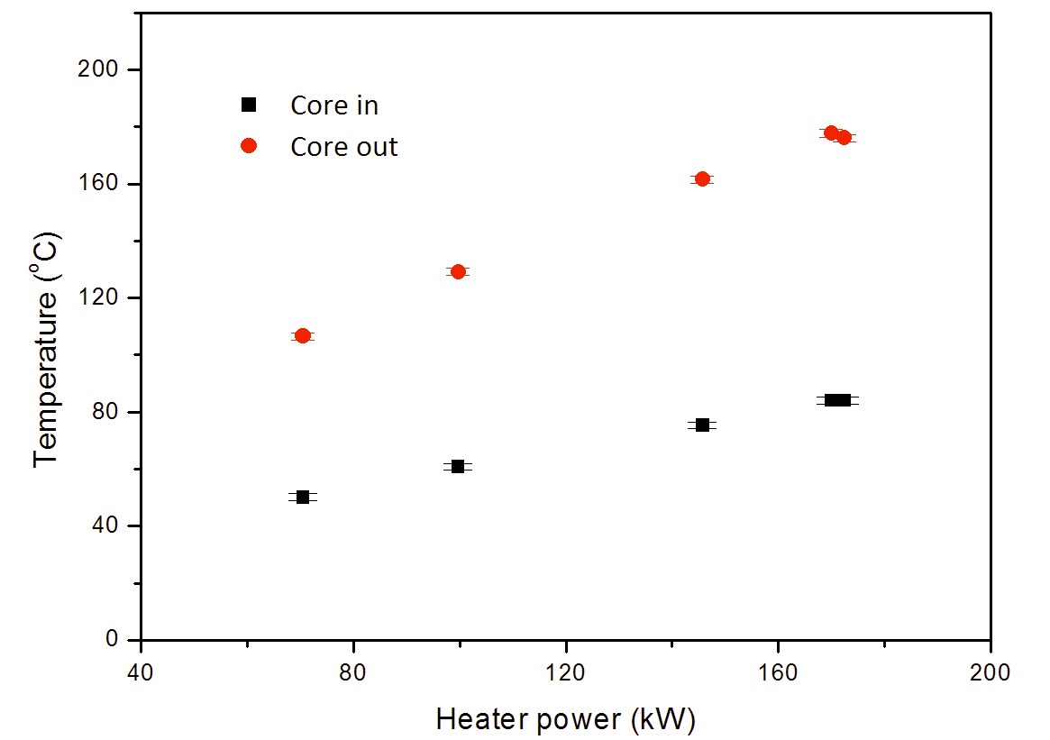
This section deals with the experimental results of the RTF steady-state natural circulation tests in Phase 1 [10]. It is noted that the type of the pressurizer has little effect on determining the steady-state mass flow rate and the temperature distribution in the primary circuit. This part of the results from Phase 1 is presented to describe the equilibrium characteristics of natural circulation in the RTF cooled by the helical-coil steam generator. The measured mass flow rate and the coolant temperature from five tests using different core powers are plotted in Figs. 8 and 9, respectively. In all cases, the secondary feedwater of 20 ℃ and 1 bar is sent into the helical coils at a rate of 4.5 LPM per tube. The heat loss to the surrounding environment is estimated to be less than 5%. From the uncertainty analysis, the maximum measurement errors of mass flow rate and coolant temperature are estimated as ± 3.8% of the reading and ± 1.3 K, respectively.
The natural circulation flow rate rises with an increase of the input power since a high input power increases the
temperature gradient of the coolant, and subsequently, the buoyancy force arising from the density differences. It is observed that the maximum flow rate in the RTF is below 0.5 kg/s for the power ranges investigated in the tests; it is quite less than the scaled mass flow rate of REX-10 as discussed in Sec. 3.1. The Reynolds number in the core region is at most 1,600. Thus, in a view of similarity, the core cooling capability of the RTF may be somewhat distorted from the prototype. It also results in a dissimilar energy distribution, i.e. the expanded temperature rise across the core, in the loop. As the core power level rises, the coolant temperatures are stabilized at higher levels as shown in Fig. 9. This is because the RCS requires a larger temperature difference across the tube walls of the heat exchanger to wholly remove the increased heat input. When the maximum core power is applied to the RTF, the core outlet temperature reaches 190 ℃.
These steady-state tests account for the effects of core power on a natural circulation flow based system. In summary, not only the natural circulation flow rate but also the temperature rise across the core and the mean coolant temperature are increased as the heat input rises. While these experiments of Phase 1 provide a better understanding of natural circulation characteristics in an integral reactor system, the steady-state results of Phase 2 are meaningful in that the fully-passive operation of REX-10 is simulated. It is verified that, by means of the steam-gas pressurizer as well as the natural circulation cooling, the scaled facility of REX-10 can maintain stable operation conditions with no active device.
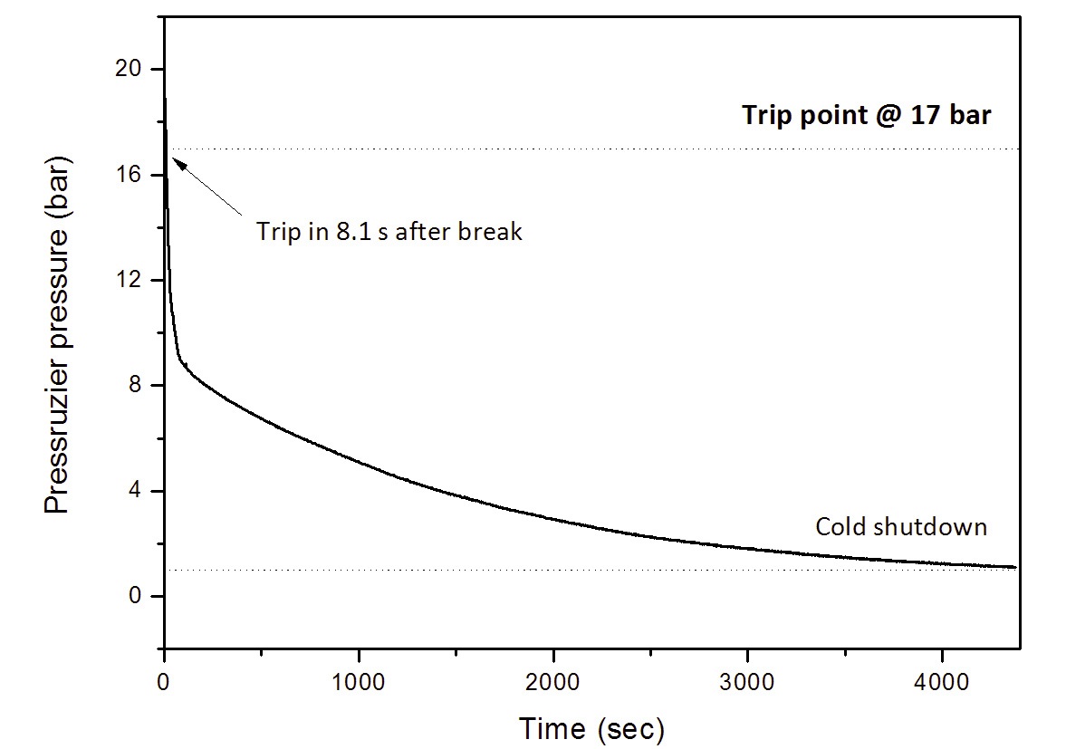
This SBLOCA experiment represents a 1/4 inch diameter break in the nitrogen injection line to the steam-gas pressurizer. Though the integral layout of REX-10 can eliminate the LBLOCA by design, one of the most severe accidents, SBLOCA, can still be initiated by a rupture at the nitrogen injection line through which the gaseous mixture is immensely discharged. As analyzed in Sec. 3.1, this test is homologous to the SBLOCA in the prototypical REX-10 whose designed nitrogen injection line is 0.045 m in diameter. The system depressurization by the break at the top of the RPV and corresponding thermal-hydraulic behavior of the RTF are investigated in this test. Major thermal-hydraulic parameters during the SBLOCA experiment are plotted in Figs. 10 ? 15.
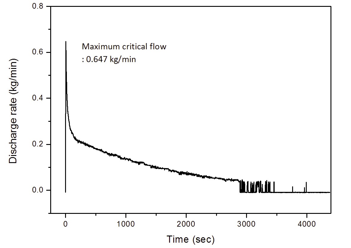
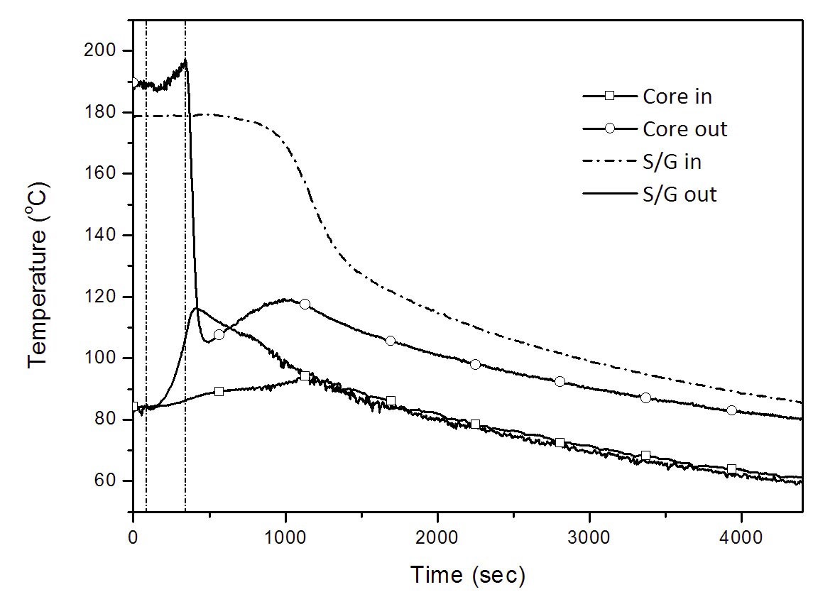
The pressurizer pressure falls to the trip setpoint, 17 bar, 8.1 s after opening the vent valve. Then the heater power is reduced to 12.5 kW instantaneously, and the feedwater flow rate is also adjusted to 0.5 LPM per tube to simulate the actuation of the PRHRS. The maximum discharge mass flux through the break is measured to be 340 kg/m2s, and the depressurization of the RTF induces radical internal flashing. The mixed flow of steam and nitrogen is discharged at the initial stage of the transient. But, as time passes, the amount of nitrogen that resides in the pressurizer reduces more quickly than steam and in the end only steam, generated by flashing, comes out of the rupture.
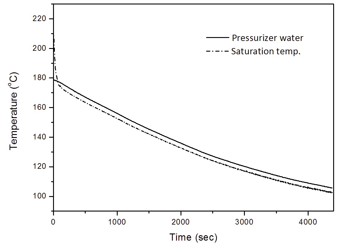
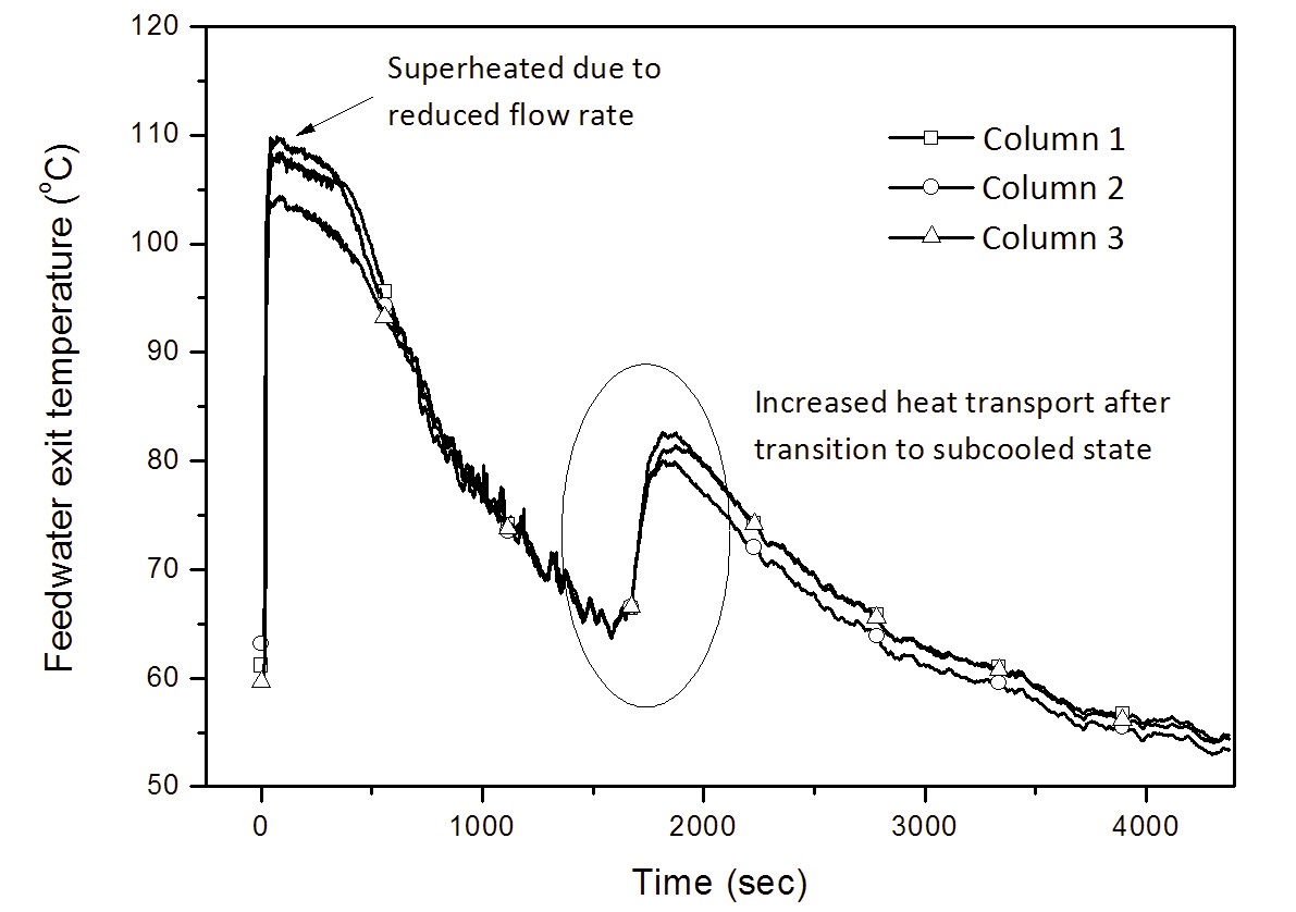
Even though the reactor shutdown is followed by a rapid drop in the core exit temperature, the coolant in the annular space above the S/G region gets saturated for a while as shown in Fig. 12. The saturation lasts until 1700s,
and then a transition into the single-phase (subcooled) flow occurs by continuous cooldown of the PRHRS. At this moment, the heat transport to S/G is increased suddenly as observed in Figs. 12 and 15. While the hot fluids between the core outlet and the steam generator inlet are saturated, a counter-current flow is established in the hot legs and the S/G inlet plenum regions. The rising bubbles apply interfacial drag forces to the liquid flowing downwards, and this considerably reduces the hydrostatic head for natural circulation. After the transition into the subcooled liquid, the mass flow rate is increased instantly as the interfacial drag vanishes. It subsequently results in a sharp increase of the heat transport from the primary to the secondary side of the helical-coil S/G.
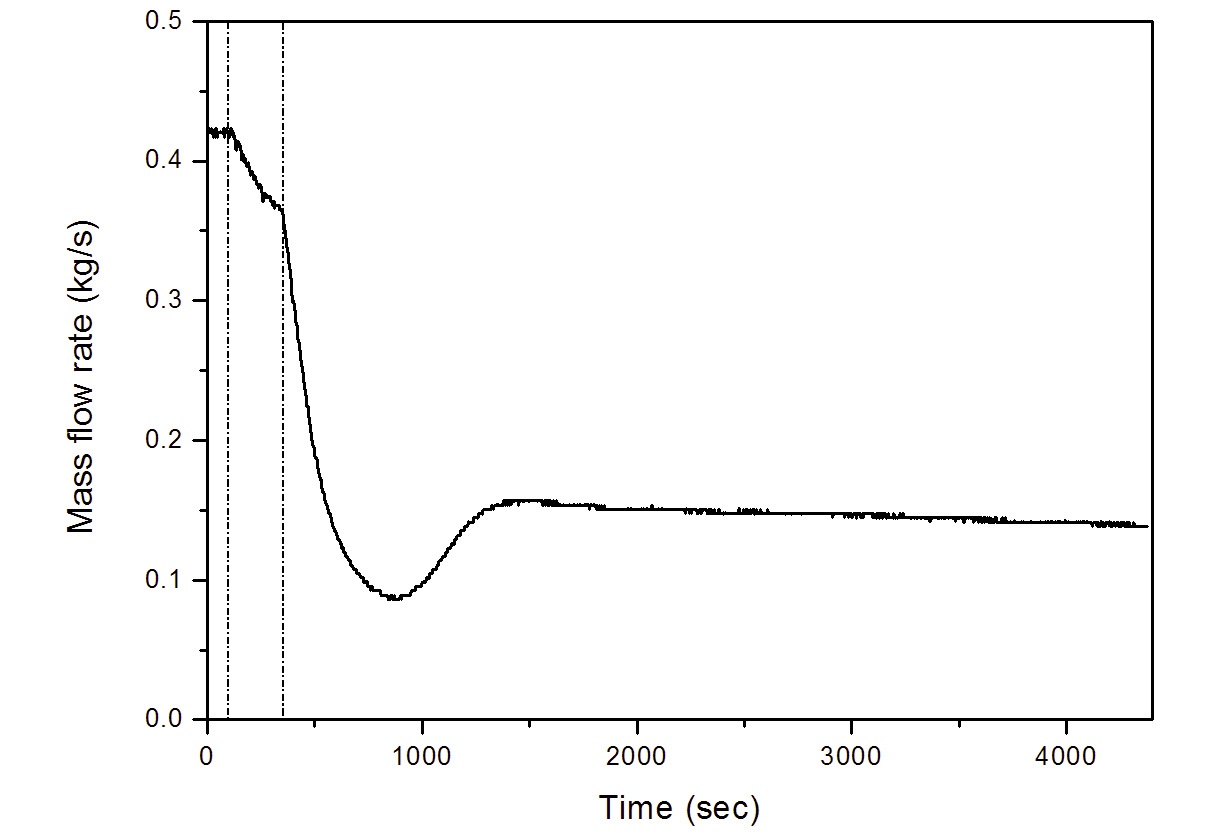
By the simulated PRHRS flow, the coolant temperatures of the RTF continue to decrease. The two-phase blowdown results in a gradual pressure decrease as the steam is expelled. At about 4400 s, the RTF is finally brought to the cold shutdown. With regard to the mass flow rate, the measurement by a turbine flowmeter may be incorrect for the two-phase flow. It is confirmed, however, that the natural circulation flow rate is stabilized at ~0.15 kg/s after the transition to the subcooled state when the single-phase heat transfer is established again.
An interesting phenomenon observed in the SBLOCA experiment is the thermal stratification of the coolant in the RTF. Figure 13 shows that the liquid in the steam-gas pressurizer is saturated for the entire transient. The primary system of an integral reactor can be considered as a long vertical flow channel. The hot liquid layer floats at the top of the vertical channel, i.e. the pressurizer vessel, by thermal stratification. Regardless of the cooldown of the RCS, the temperature of the stratified liquids in the pressurizer is maintained at the saturation value corresponding to the system pressure. The results of this experiment reveal that, under the cooldown transients of an integral PWR, the liquid conditions in the steam-gas pressurizer are rarely affected by the coolant temperature in the main flow paths.
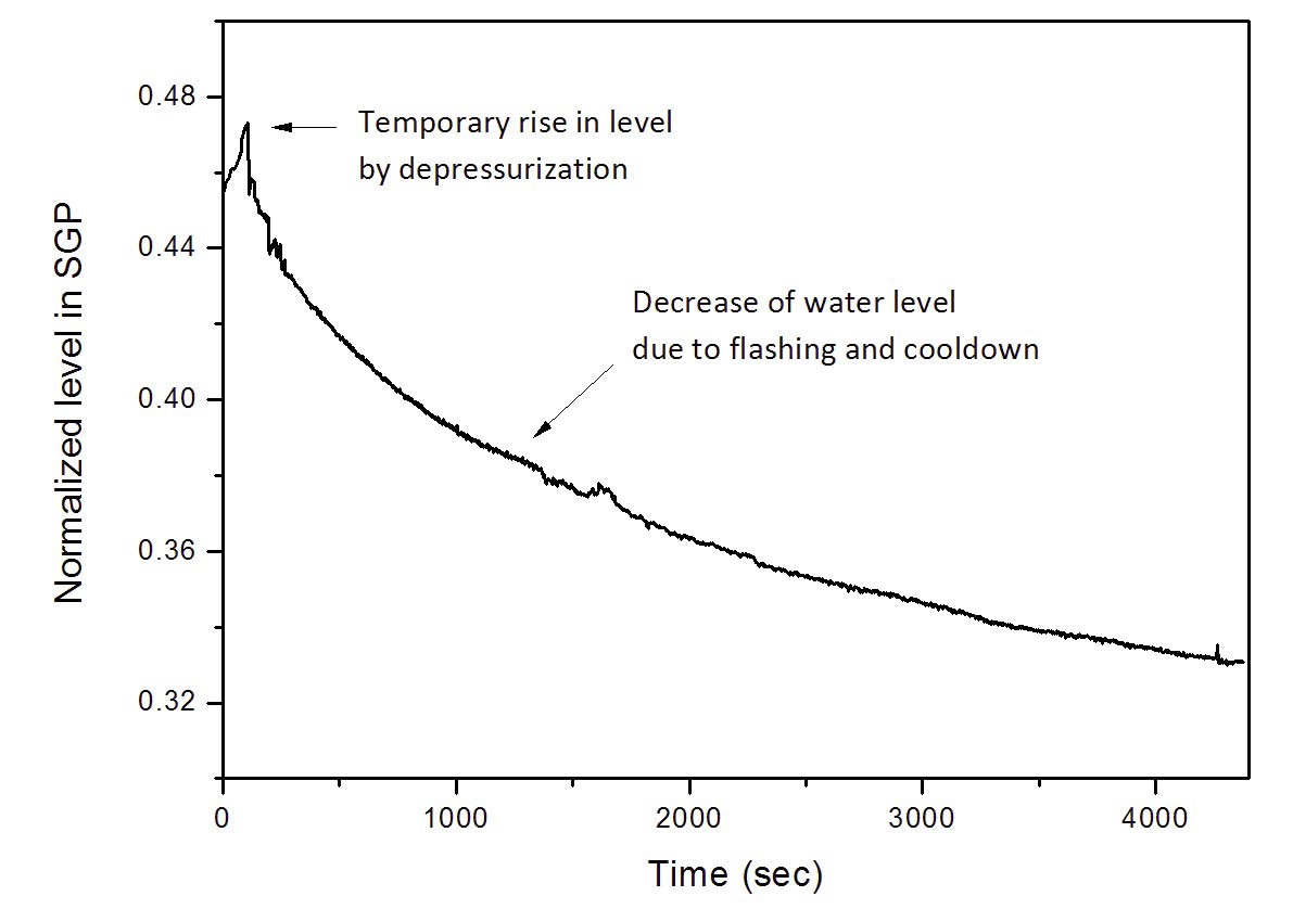
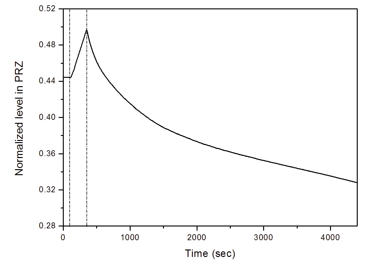
Figure 14 shows that the water level in the pressurizer is continuously reduced by the internal flashing and the coolant cooldown. However, the pace is very moderate. The water level in the pressurizer is a direct indication of the RCS coolant inventory in the integral PWR. If the water level goes below the entrance of the hot legs, the flow path of the liquid coolant will be cut off and the bulk boiling in the core and riser regions will accelerate. Unlike a general SBLOCA in which the break point is located below the RCS water level and the steam-water mixture is expelled, a SBLOCA at the steam-gas pressurizer causes a gradual decrease in the RCS coolant inventory as the gaseous mixture is discharged in the event. The RTF is brought to a stable state without a cut-off of coolant circulation or core uncovery. The experimental results imply that REX-10 may readily assure sufficient coolant inventory in response to the SBLOCA at the pressurizer vessel if a proper safety injection system is incorporated.
Through the SBLOCA experiment, the system depressurization, accompanied by internal flashing and two-phase natural circulation flow, and the transient RCS responses
with passive core cooling are investigated when the break is located above the coolant level. The loss of coolant inventory is very moderate in this accident, and a stable core cooling is established by natural circulation of the primary coolant and simulated operation of the PRHRS. During the two-phase blowdown period, the counter-current flow takes place in the annular flow passage above the S/G where the liquid flows downwards. Rapid increase in the heat removal from the S/G is also observed as the primary coolant conditions are totally brought to the subcooled state.
The second accident test simulates a hypothetical accident induced by the complete loss of feedwater flow in which the S/G no longer serves as a heat sink until a protective system is actuated. This total loss of feedwater flow can be caused by a mechanical seizure or a power failure of feedwater pumps, or an inadvertent closure of the feedwater control valves due to malfunction of the feedwater control system [16]. Through this experiment, the pressure responses and the transient natural circulation of an integral PWR with a steam-gas pressurizer is investigated in the absence of the heat sink. In particular, the pressurization transient of the LOFW event is studied with two types of pressurizer. Then the relative performances of pressurizers are compared, and the thermal-hydraulic features of the steam-gas pressurizer are discussed in this section.
When an actual reactor system experiences a LOFW event, the core is immediately tripped by a low feedwater flow trip signal. In this test, however, a more conservative scenario is assumed for conservative evaluation of the safety features of REX-10; the reactor is shutdown not by the immediate detection of low feedwater flow, but by the high pressurizer pressure trip without prompt mitigation of the event. In this case, the core power is applied continuously to the primary coolant without heat removal and the thermal energy is accumulated in the primary system. Then the PRHRS begins to operate at much higher pressure and temperature conditions in this scenario. In addition, more heat removal is required to reach the cold shutdown state compared to the situation in which the reactor is immediately shutdown. Thus, if one proves that the RTF can be brought to a stable state by operation of the PRHRS in this conservative scenario, it indicates that the RTF assures sufficient cooldown capability during an actual LOFW transient with no pressurization process.
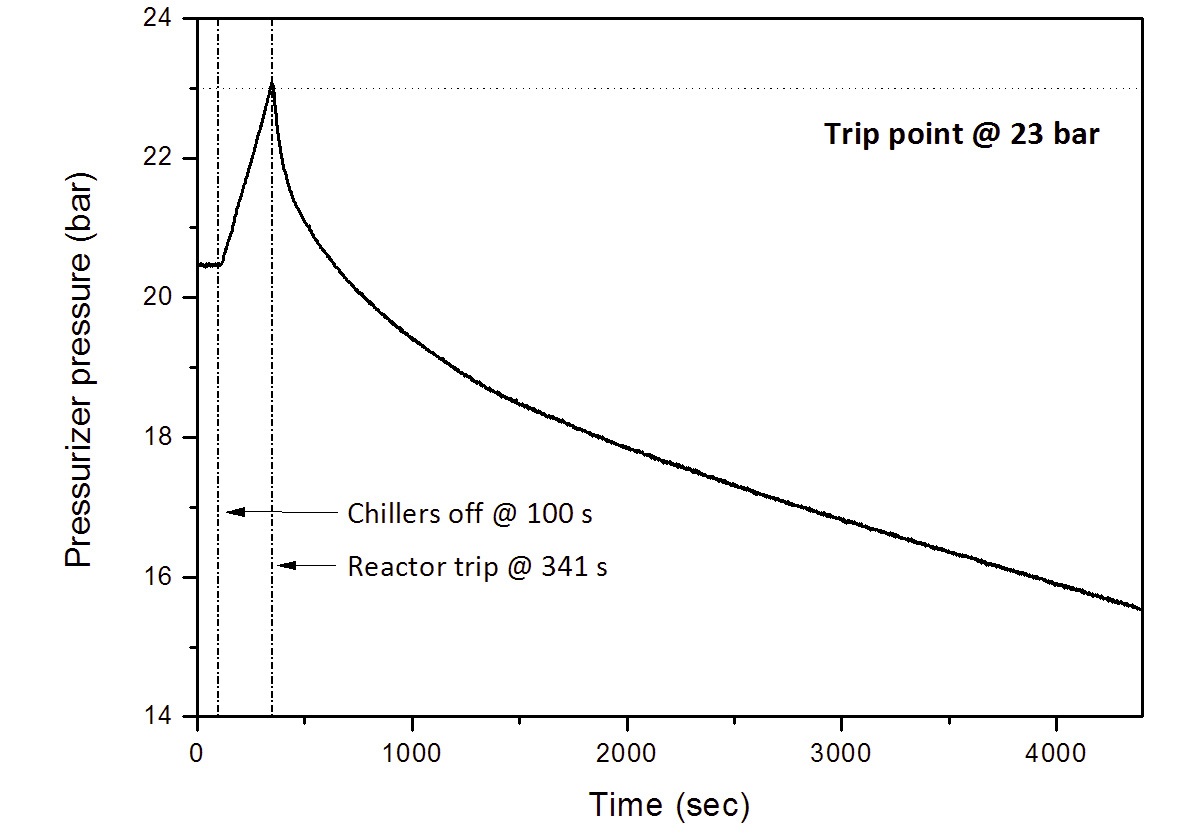
Experimental results of the LOFW experiment in the RTF are shown in Figs 16 ? 19. After the chillers are turned off, the coolants in the primary circuit are heated up at the rated power while the heat sink vanishes. Meanwhile, the RCS coolants expand and the hot insurge water flows into the steam-gas pressurizer. The reduction in the volume of gaseous mixture and the increase of the liquid temperature in the steam-gas pressurizer cause the rise in the partial pressure of the non-condensable gas and the vapor, resulting in higher pressurization of the RTF. The overpressure trip occurs 240s after the initiation of the transient, and accordingly, the prescribed decay heat and PRHRS flow are provided.
During the pressurization transient (from initiation to reactor trip) period, the natural circulation flow rate is gradually reduced due to the absence of the heat sink. Even so, the core cooling capability is maintained for a while. The coolant temperature at the core outlet increases by about 8 K, but the bulk boiling of the coolant does not occur in the RTF. This observation implies that the thermal margin for the core outlet temperature is of great importance for the safety aspects of integral PWRs operating on natural circulation.
After the reactor trip, the RCS coolant temperatures are gradually reduced on account of the stable, continuous cooldown by the PRHRS. Accordingly, the water level in the pressurizer and the system pressure continue to decrease. Since the initial mass of the nitrogen is retained during the transient, the decline of the pressurizer pressure is quite moderate compared to the SBLOCA experiment. The thermal stratification in the liquid region of the steam-gas pressurizer is observed as usual. Since the interaction between the liquids in the pressurizer and the RCS coolants is not active during the cooldown transient, the vapor partial pressure in the steam-gas pressurizer declines very slowly. It can be inferred from the results that if the PRHRS is designed and installed so that the natural circulation flow rate in the PRHRS train is at least 1/9 of the nominal feedwater flow rate, integral PWRs such as REX-10 can assure sufficient cooldown capability under these kinds of accident conditions.
For the pressurization transient in the LOFW accident, the same test is repeated while implementing the general concept of the steam pressurizer instead of the steam-gas pressurizer. In other words, instead of injecting the noncondensable gas, the upper volume of the pressurizer vessel is filled with pure vapor in this supplementary test. From this test, the performances of these two types of pressurizer are compared to each other for the insurge transient caused by the coolant heat up. In the test with the steam pressurizer,
the RTF is pressurized by using the immersion heaters to evaporate the water. At the steady-state, the heater power is maintained at a level that compensates for the heat loss to the surroundings, i.e. 2.1 kW in this test.
Transient system pressures when employing the steam pressurizer and the steam-gas pressurizer are plotted in Fig. 20. For 240s, which is the time required for the RTF with the steam-gas pressurizer to reach the high pressurizer pressure trip condition, the total pressure of the steam pressurizer increases by just 0.8 bar. The rate of the pressure rise during the LOFW accident in the RTF that employs the steam-gas pressurizer is three times faster than the RTF that employs the steam pressurizer. This result verifies that, for an identical insurge transient, the steam pressurizer has better performance in absorbing the pressure transient by the insurge flow even without using a spray.
During an insurge transient, the pressure rise is partially suppressed by the condensation heat transfer on the wall. When pure vapor exists in the upper volume of the pressurizer, a rise in the steam pressure is effectively retarded by furious wall condensation and inter-region heat and mass transfer. In the steam-gas pressurizer, however, the presence of the non-condensable gas significantly reduces the condensation heat transfer [17], and the reduction in the volume of the gas phase leads to a corresponding increase in the partial pressure of the non-condensable gas. This is why the RTF with the steam-gas pressurizer undergoes faster pressurization during the LOFW event. The above results reveal that the performance of the steam pressurizer is better than the steam-gas pressurizer for an insurge transient.
Even though the capacity of the steam-gas pressurizer is not as effective as the conventional concept, REX-10 implements a higher level of passive features in operation by employing it. The steam-gas pressurizer excludes active systems needed for an artificial control, and maintains the system pressure by containing a non-condensable gas in the cover gas. REX-10 can be operated in a passive manner. In addition, the reactor system of REX-10 is made more compact as auxiliary equipment related to active systems such as heaters or spray is eliminated. Therefore, the steamgas pressurizer can be deliberately considered as a component to accomplish the passive operation of an integral PWR.
To evaluate the transient RCS responses and assess the safety performance of REX-10 during the postulated DBAs, integral effect tests on SBLOCA and LOFW accidents are performed in the RTF, which is a full-height full-pressure facility equipped with a steam-gas pressurizer. For both tests, the RTF is successfully brought to the cold shutdown owing to the continuous cooldown by the supposed PRHRS flow without core uncovery or temperature excursion. Thermal stratification of the liquid in the pressurizer is commonly encountered. This suggests that, in this integral PWR which has the pressurizer at the upper volume of the RPV, the cooldown of the coolant does not lead to immediate decline of the vapor partial pressure in the steam-pressurizer.
In the SBLOCA test, the reduction in the coolant inventory by the discharge of gaseous mixture is quite moderate, and the RTF is brought to the cold shutdown before the liquid flow circulating in the primary system is cut off. For the pressurization transient in the LOFW, the steam-gas pressurizer undergoes a faster pressure rise compared to the steam pressurizer on account of a substantial decrease in the condensation heat transfer due to the presence of nitrogen.
The testing program presented in this paper is an experimental investigation on REX-10 characterized by passive safety features. In this regard, the output from this IET can provide unique and valuable data to understand the transient behavior of an integral PWR during accidents. Moreover, it is expected that the experimental data from this testing program will be utilized to validate a thermalhydraulic system code for analysis of an integral PWR.
A Cross-sectional area (m2)
cp Specific heat at constant pressure (J kg-1K-1)
d (hydraulic) Diameter (m)
f Darcy friction factor
g Gravitational acceleration (m s-2)
K Minor loss coefficient
l Length (m)
P Core power (W)
R Loop resistance expressed as
u Velocity (m s-1)
Greek Letters
β Volumetric expansion coefficient (K-1)

Core-averaged density of coolant (kg m-3)
Δz Elevation difference between core and S/G (m)
Subscripts
i i-th component
NC Natural circulation
R Ratio of model to prototype
t Throat
0 Reference point / component