The United States Nuclear Regulatory Commission (NRC) established Generic Safety Issue (GSI)-191 to determine whether the transport and accumulation of debris in pressurized water reactor (PWR) containments following a loss-of-coolant accident (LOCA) could impede the operation of PWR emergency core cooling systems (ECCSs) or containment spray systems (CSSs) [1]. In the event of a LOCA, the materials in the vicinity of the break (e.g., thermal insulation, coatings, and concrete) could be damaged and dislodged. The material could then be transported to the recirculation sump and may accumulate on its strainer (or screen). Debris transported to the sump strainer has a tendency to form a bed, which, much like a filter, could increase head loss across the sump strainer. The flow restriction at the sump strainer can threaten the safety margin required to assure the successful operation of ECCS and CSS pumps after the LOCA. In addition, chemical precipitates, which mean solid particles formed by chemical reactions between dissolved chemical species in solution, can form, interact with fibrous debris bed, and aggravate the sump strainer blockage possibly to an extreme condition, i.e., no water flow through the fibrous debris. This phenomenon is called “chemical effects.” The formation of the chemical precipitates in the post-LOCA ECCS recirculation water is a reasonable assumption. High concentration of boron is present in the primary water, and containment spray solutions may be injected at high pH values depending on the plant design. The containment spray water can cause the corrosion of metallic components and the release of metallic ions into the post-LOCA cooling water. Even after the cease of the CSSs, submerged surfaces of metallic components, insulations, concrete, coating etc. in the ECCS recirculation water would still be subject to corrosion or chemical reactions over a long period of time (typical mission time is 30 days).
If the sump pump cannot provide enough cooling water to a reactor core because of the strainer blockage, this can lead to a serious consequence like core damage. To help resolve the NRC GSI-191, the NRC issued Generic Letter (GL) 2004-02 outlining schedules for licensees to complete PWR sump performance evaluations and if necessary, sump modifications and procedure changes [2]. The PWR sump performance methodology requires an evaluation of chemical effects, including the potential consequences of chemical precipitates on head loss across the sump strainer, on plantspecific basis. Since then, various industry- or NRC-led researches have been performed in the U.S., specifically on the chemical effects.
The objective of the current article is to review the research efforts in the U.S. to resolve the GSI-191 chemical effects. This review is limited to the PWR sump strainer works. The downstream in-vessel chemical effects are excluded in this review, which are still on-going efforts by plant licensees and NRC. The efforts in the other countries related to the chemical effects on the sump strainer blockage are also excluded (for examples, see references [3-6]).
2. RESEARCH EFFORTS PRIOR TO INTEGRATED CHEMICAL EFFECTS TEST
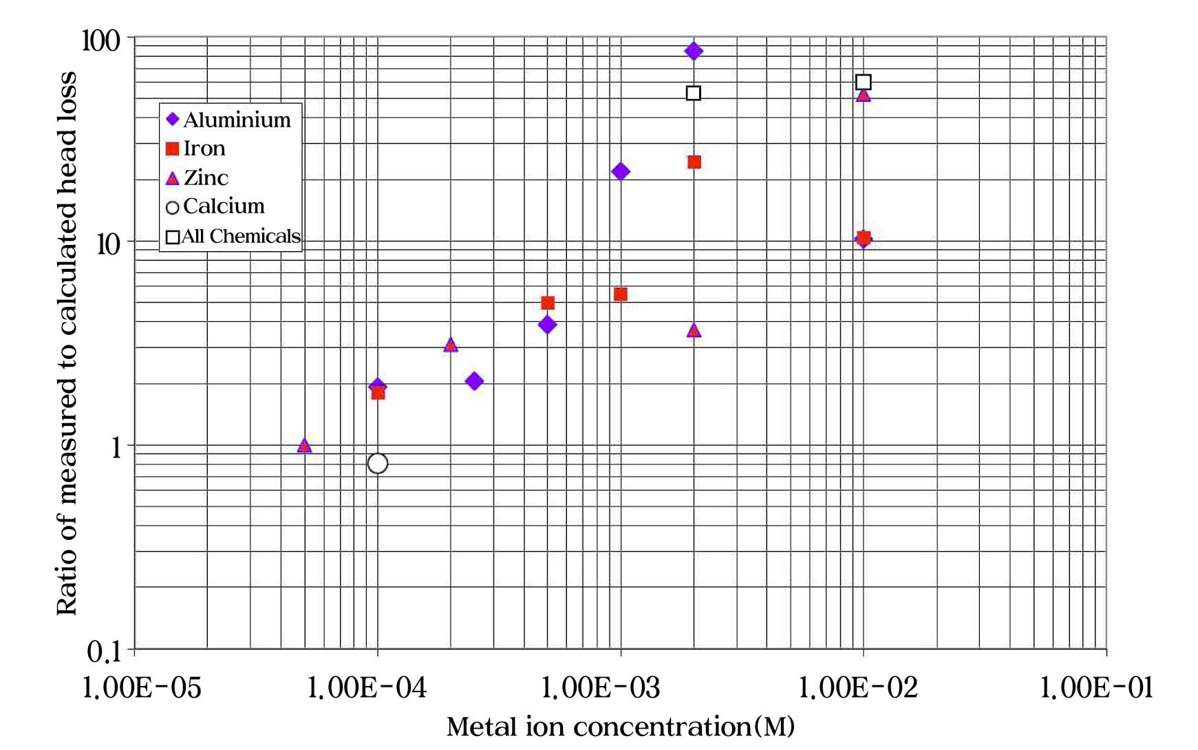
The NRC initiated a small-scale chemical effects test in response to a concern raised by the Advisory Committee on Reactor Safeguards (ACRS) during its review of staff activities related to the resolution of GSI-191 in February 2003 [7]. Specifically, the NRC ACRS raised the concern that chemically induced corrosion products have the potential to impede ECCS recirculation after a LOCA. Under this study, several small-scale head loss tests were conducted to determine whether debris generation and sump strainer head loss can be affected by chemical interactions between the ECCS recirculation water and exposed metal surfaces [7-8]. The principal conclusions are that it is possible for gelatinous materials, if formed, to transport to PWR sump strainers, and that such materials can increase head loss across a fibrous debris bed. These results lend credibility to the concerns raised by the ACRS. Figure 1 shows the ratio of the measured head loss as a function of metal ion concentration. The head loss with chemical precipitates was normalized by the head loss without chemical precipitates. In the case of aluminum, the head loss with chemical precipitates is almost two orders of magnitude higher than that without chemical effects.
Even though this study showed the significance of chemical effects, the scope of the work was limited; only
sodium hydroxide (NaOH) was used as a pH buffering agent, and metal salts (as nitrate forms) were added to the test loop. Only separate-effects tests were performed for each potential stage of the progression. As a result, the study did not include integrated tests to demonstrate the complete progression of chemical effects from metal corrosion to the ultimate formation of precipitation products. Three NRC-sponsored research activities described in the following sections are follow-on studies to implement the findings in this study.
3. INTEGRATED CHEMICAL EFFECTS TEST (ICET)
The Integrated Chemical Effects Test (ICET) project was a joint effort by the NRC and the nuclear power industry [9-10]. The ICET attempted to simulate the chemical environment in a containment water pool after a LOCA and monitored the chemical system for 30 days to identify the presence, composition, and physical characteristics of chemical products that formed during the tests. The primary objectives were to determine, characterize, and quantify chemical-reaction products that may develop in the containment sump under a representative post-LOCA environment, and identify and quantify any chemical precipitates that might be produced during the post-LOCA recirculation phase [9]. No measurements of head loss were made in the tests. The head loss testing conducted by Argonne National Laboratory (ANL) is discussed in a later section of this article.
All of the ICETs were conducted in an environment that attempted to simulate containment pool conditions during recirculation. The tests included an initial 4-hr spray phase to simulate containment spray interaction with the non-submerged materials. The materials present in this environment included representative amounts of submerged and non-submerged aluminum, copper, concrete, zinc, carbon steel, and insulation samples. Representative amounts of concrete dust and latent debris (dirt) were also added. Insulation samples consisted of NUKON fiberglass and calcium silicate (CalSil). Water was circulated through the bottom portion of the test chamber during the entire test to achieve representative flow rates over the submerged specimens. The amounts of material in the test were scaled to the liquid volumes of the test chamber and the containment sump volume. Detailed plant survey information was available after testing, and indicated the amount of insulation (e.g., CalSil) in these tests may have been too high to be representative.
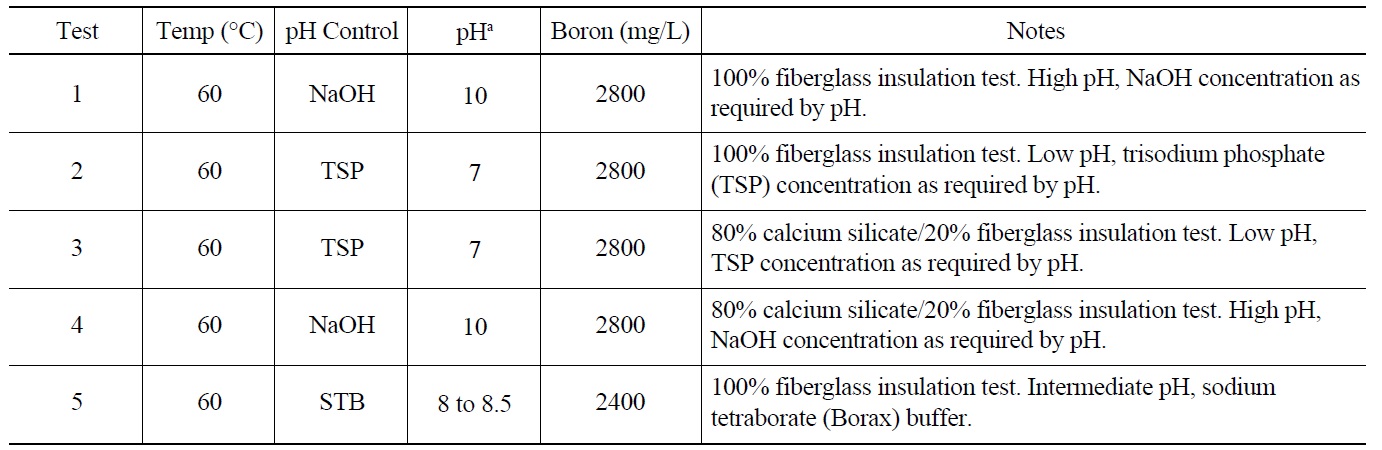
The physical and chemical parameters that defined the tank environment are summarized in Table 1. The pH of the initial test solution was different for each test because three different pH control agents were used: NaOH, trisodium phosphate (TSP), and sodium tetraborate (STB). The
[Table 1.] Test Parameters of the ICET Series [9].
Test Parameters of the ICET Series [9].
solution pH varied from ?7.3 (Test 2) to ?9.8 (Test 4). Several different combinations of the test solution pH and insulation materials were tested. The predetermined amounts of chemicals were added for each test, and no attempt was made to control or alter the resulting pH during the test. The test materials were introduced to the tank as 373 flat-metal coupon samples (40 submerged) and one submerged concrete sample. Flow rate and temperature were controlled to maintain target values of 25 gpm and 60℃. The solution was sampled daily for measurements.
3.2 Important Findings and Discussion
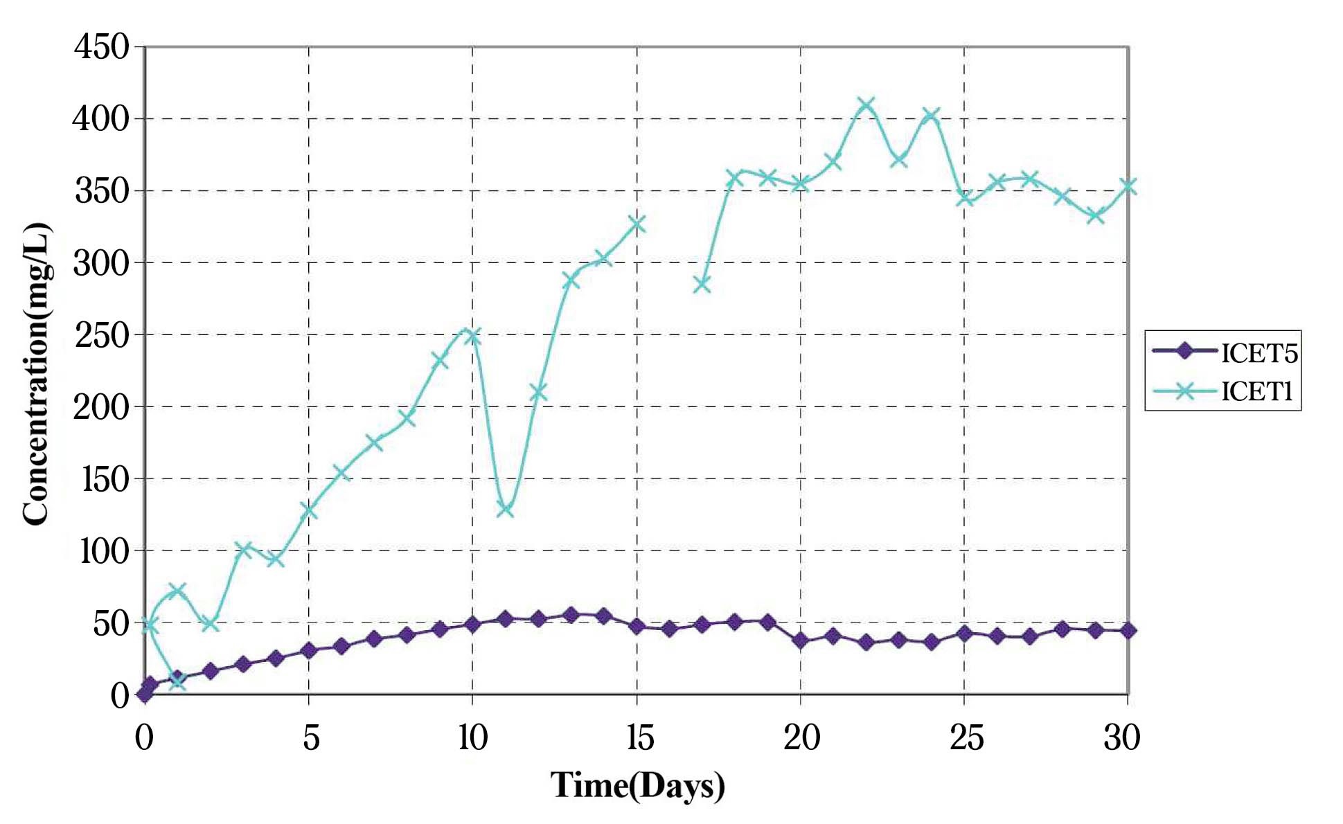
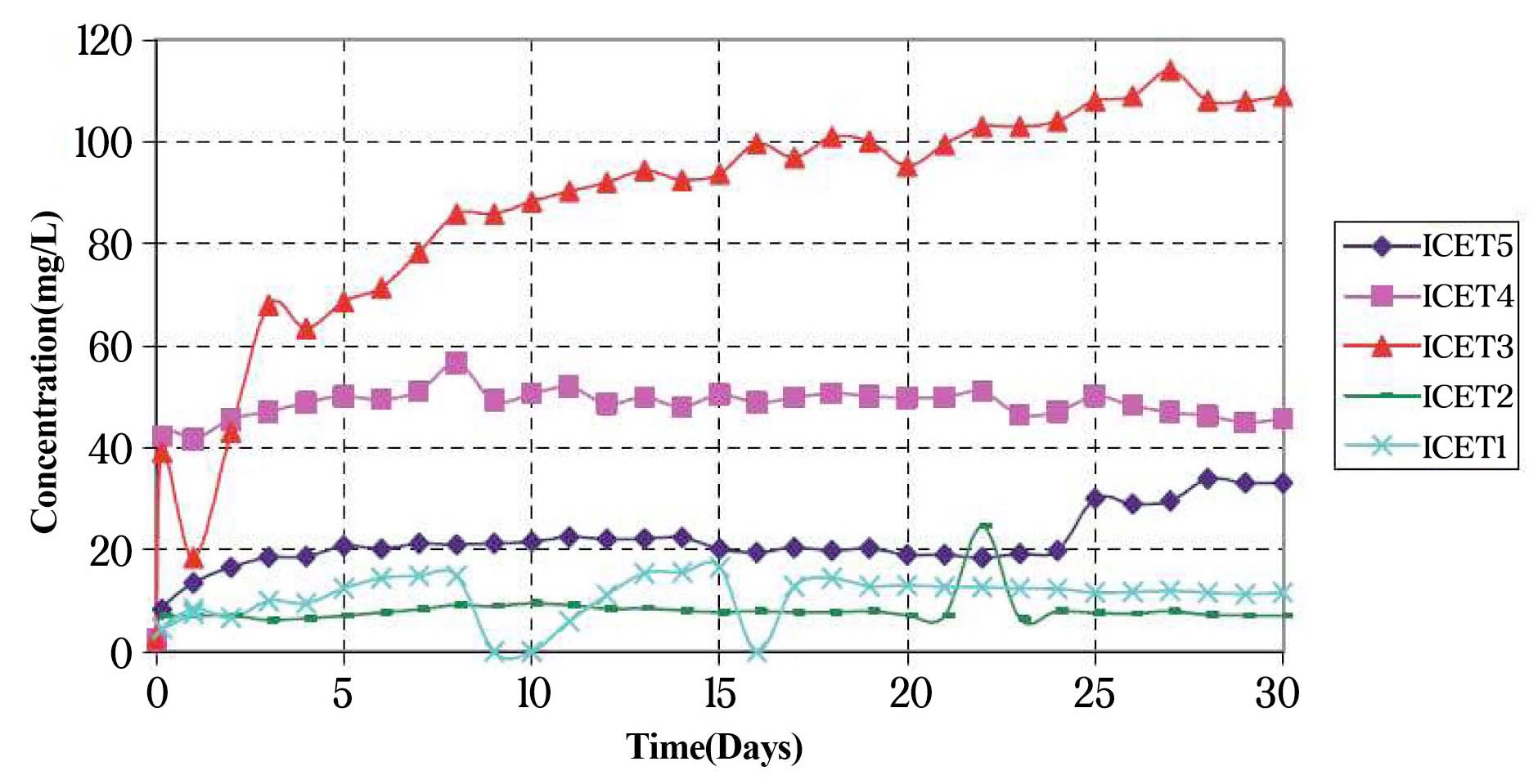
Aluminum hydroxide, Al(OH)3 or related forms, and calcium phosphates are the primary chemical precipitates in the ICET tests. Significant dissolution of aluminum was observed in solutions with pH of 8.0 or greater, as shown in Fig. 2. Calcium phosphates were formed in solutions with TSP and CalSil, which was observed in Test 3. The formation of the calcium phosphates occurred early in the test by the reaction between dissolved Ca and phosphates. Measured Ca concentrations are shown in Fig. 3. Calcium levels in Tests 3 and 4 are high due to the presence of large amount of CalSil. Concrete and other insulation materials are other potential sources of dissolved Ca that could react with TSP to form calcium phosphate. Rapid formation of calcium phosphate precipitate may be especially detrimental because the safety margins of sump pumps are typically at a minimum near the switchover to ECCS recirculation.
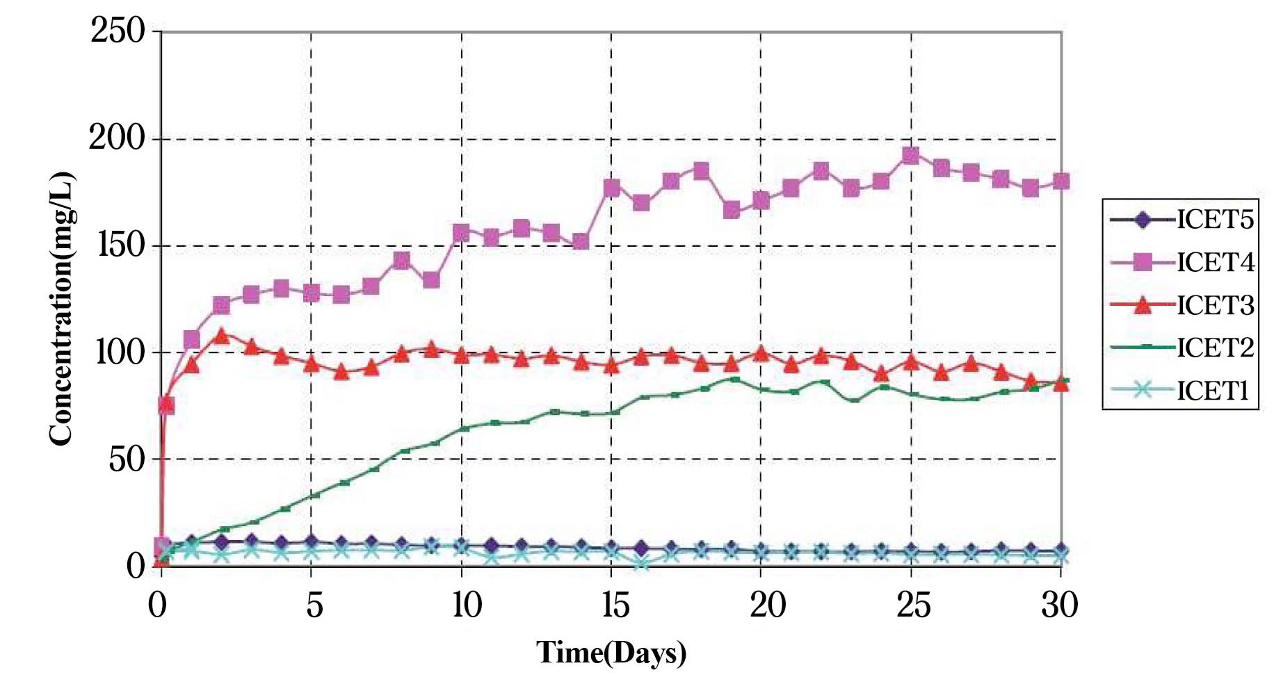
Another noticeable finding from the ICET results is the potential inhibition effects of dissolved species on other materials. The results suggest that fiberglass dissolution (i.e., leaching of Si) could be inhibited by the presence of dissolved Al (Test 1) and Al corrosion could be inhibited by the presence of dissolved Si (Test 4). Fig. 4 shows the measured silicon concentration in Tests 1-5. The Si level of Test 1 is unexpectedly low even at high pH compared with the level of Test 4. It appears that dissolved aluminum in Test 1 quickly reacted with the fiberglass to coat it. The
ICET results show that solution chemistries observed in complex multicomponent environments are not always consistent with those predicted on the basis of tests in simpler environments. The concentrations of dissolved silicon in Test 1 are much smaller than those predicted from tests on fiberglass in solutions with comparable pH value [11] because of the inhibition effect of aluminum in solution. The low concentrations of dissolved aluminum in ICET Test 4 provide a strong evidence for the potential for passivation of aluminum in solutions with large amounts of Si in the solution by forming aluminum silicates. In this respect, the large amount of CalSil in the ICET tests is nonconservative on the amount of Al corrosion. Westinghouse data reported in WCAP-16530-NP [12] indicates a 75 ppm threshold silica inhibition level for Al passivation, with a marked decrease in aluminum corrosion at a 50 ppm concentration. Aluminum phosphates are also highly insoluble, making phosphates a candidate inhibitor (if no CalSil is present) [13]. Passivation also occurred in Tests 1 and 5 after 15 to 20 days. At the low concentrations of dissolved silicon in these tests (? 8 ppm), it is not clear whether the mechanism of passivation in these tests was related to the formation of aluminum silicates. It is also not clear how to “credit” passivation in such environments based on the various ratios of aluminum surface area, fiberglass volume, pH, other materials, etc. When passivation occurs, use of the average corrosion rate over the whole test period gives non-conservative estimates of the amount of corrosion that will occur during active dissolution, before the material becomes passivated.
In the plant, contrary to the constant temperature condition in ICET tests, the recirculated water is cooled by the shutdown cooling heat exchangers. The temperaturecycling may affect the solubility and reaction kinetics of precipitates. Therefore, the temperature-cycling effect by heat exchangers on precipitation needs to be further investigated. This was partially investigated by ANL [14] suggesting that the rapid thermal cycling does not appear to affect chemical precipitation. The initial aluminum precipitation product is amorphous. Eventually, it will transform to the more stable, crystalline form. The crystalline form is much less soluble than the amorphous form, and any portion of the precipitate that is transformed would be less likely redissolved at higher temperatures. However, it is noted that this transformation would take time, depending on temperature and solution chemistry.
3.3 ICET Aluminum Chemistry (NUREG/CR-6915)
Additional bench-scale experiments, examinations, and literature reviews [15-16] were conducted to gain a better understanding of the corrosion of aluminum and the formation of precipitation products in environments similar to ICET Tests 1 and 5 (i.e., high pH without CalSil). The precipitates that form as the ICET Tests 1 and 5 solutions cool at room temperature are agglomerations of nanometer-sized particles. The precipitate is highly hydrated, consisting of about 90% water by mass. The X-ray diffraction (XRD) and transmission electron microscopy (TEM) analyses of the precipitates of Tests 1 and 5 indicate that the precipitates were largely composed of amorphous aluminum hydroxide, with a substantial quantity of boron adsorbed onto the surface, although the XRD refinement revealed pseudoboehmite, poorly crystalline boehmite (AlOOH). The amorphous form is to be expected because of the high concentration of anions in the solution; such high concentrations of anions are known to retard crystallization at temperatures below 60℃. Also, as discussed in the report NUREG/CR-6915 [15], earlier literature showed that the crystallographic phase of aluminum hydroxide precipitation in alkaline solution depends on a degree of supersaturation; this is further discussed in an ANL letter report in terms of aluminum solubility in alkaline solution [17]. Chemical analysis indicates that up to 35% of the boron in the initial solution may have been adsorbed onto the amorphous aluminum hydroxide precipitate. The NMR measurements showed complexation between aluminum and boron. This finding corroborates the hypothesis that complexation was responsible for impeding the crystallization of aluminum compounds.
The literature reviews and a bench-scale test proved that the presence of silicon in solution can lead to inhibition of the corrosion of aluminum. Complete inhibition of aluminum corrosion was demonstrated in a bench test with a concentration of silicate inhibitor at 88.7 mg/L. This finding is in reasonable agreement with WCAP-16785- NP values [13]. It is noted, however, that the large amount of CalSil in ICET Test 4 probably produced a concentration of dissolved Si that is not representative of what would be found in the post-LOCA environment. Passivation needs to be demonstrated for representative plant-specific conditions.
4. ANL HEAD LOSS TESTING (NUREG/CR-6913)
A test loop was constructed at ANL to study the effects of the chemical products observed in the ICET tests on head loss [18]. This study considered the effect of head loss at a CalSil loading of 19 g/L (ICET 3), along with much lower CalSil loadings (0.5 g/L and less), which would be more representative of most plant situations. Most tests in the ICET 3 environments were integrated, and the chemical products were formed by the dissolution and reaction of actual containment materials. In the ICET 1 and 5 environments, surrogate chemical products (aluminum nitrates) were used. Use of the surrogate forms was justified by comparisons with the chemistry and other physical characteristics, such as the amorphous structure of the products formed in the integral ICET.
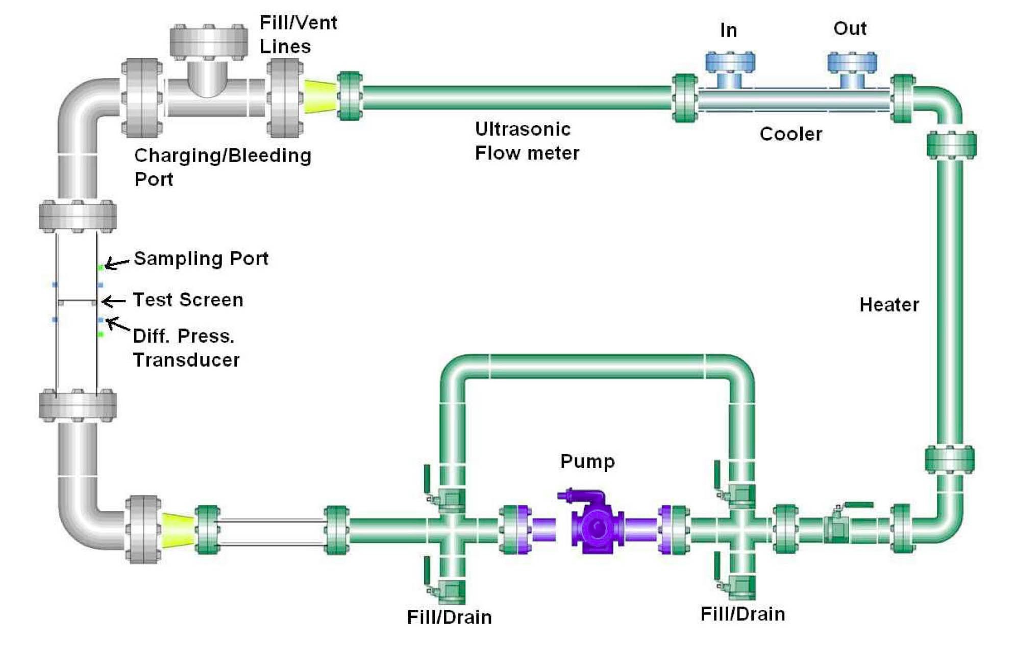
A schematic diagram of the ANL vertical head loss test loop is shown in Fig. 5. Piping in most of the loop is chlorinated polyvinyl chloride (CPVC); the clear test section
containing the test strainer was either LEXAN or clear polyvinyl chloride (PVC). The heater and cooler sections are stainless steel. Loop velocities can be controlled over the range from 0.006 to 0.6 m/s (0.02 to 2 ft/s). Fluid volume in the loop is 119 L. At 0.03 m/s (0.1 ft/s), the transit time around the loop is about 4 min. The sump strainer in these tests is a flat perforated plate. Differential pressure transducers measure the differential pressures across the strainer and bed. In scaling the results from the ANL test facility, the mass of chemical product and physical debris per unit area of strainer were considered. Physical debris and chemicals are introduced to the loop through a charging port at the top of the loop. The horizontal configuration of the strainer is not intended to reflect a realistic strainer configuration, but rather to permit the development of uniform beds with well-defined characteristics.
In the basic test procedure, the test loop was filled with deionized water and heated to 54℃ (130℉). Boric acid, LiOH, and a pH control chemical (NaOH, TSP, or STB) were added to reach desired concentrations and pH. The loop was held at temperature overnight to deaerate the liquid. NUKON and/or CalSil were used to create the physical debris bed. The insulation materials were shredded and added as slurries. Pressure drop across the bed, flow velocity, and temperature were monitored continuously. In ICET 1 environments, aluminum nitrate solutions were added to the loop after the physical debris was formed.
4.2 In ICET-3 Environments: TSP with CalSil
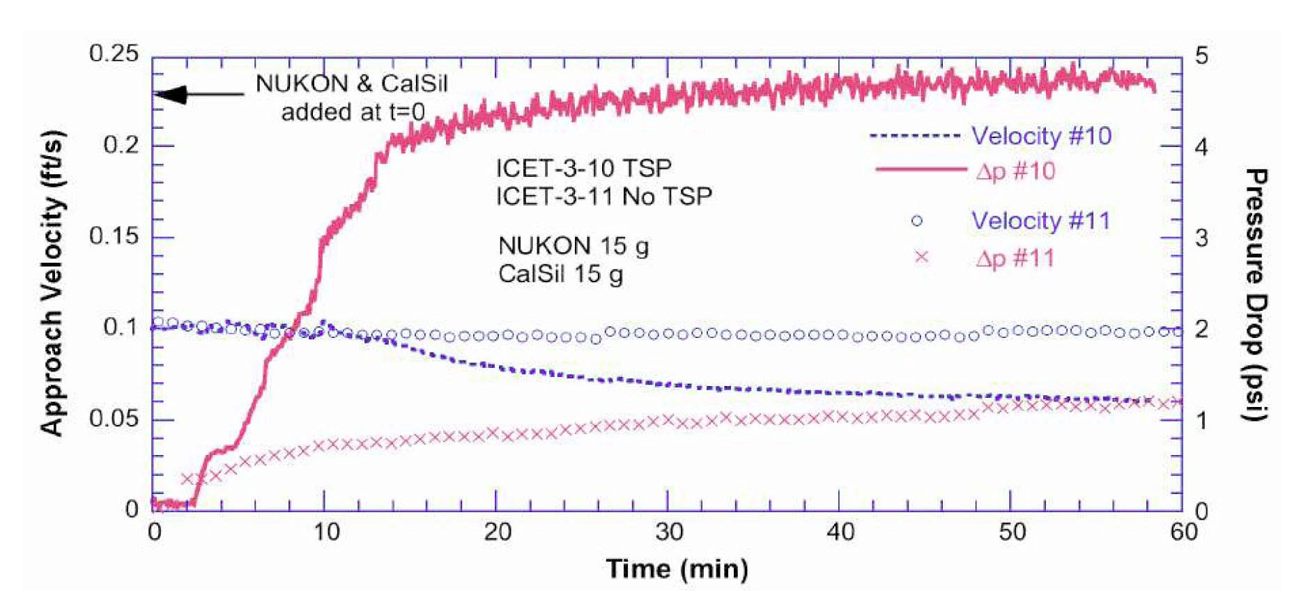
A series of head loss tests was performed to explore conditions corresponding to a range of debris amounts, dissolution of CalSil before the bed formation, and TSP dissolution time. Pressure drops across the debris bed for tests with physical debris and TSP present are compared with the baseline test, which had the same amount of insulations but without TSP. As expected, the initial pressure drop behavior of the test with TSP was similar to the baseline case. However, the pressure drop started to deviate from the baseline case, indicating the debris bed clogging by calcium phosphates. It started to rapidly deviate from
the baseline when some amount of calcium phosphate precipitates were allowed to form and arrive at the strainer as the debris bed was formed (see Fig. 6), whereas the pressure drop gradually increased when precipitation was limited as the bed was formed. The final pressure drops, however, were similar regardless of the limitation on the calcium phosphate precipitation during the bed formation.
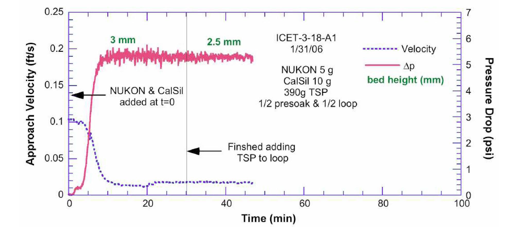
Test ICET-3-18 used debris loading of 5 g NUKON and 10 g CalSil. This resulted in a thin debris bed about 3-4 mm thick. Figure 7 shows the bed approach velocity and differential pressure across the strainer as a function of time for this test. This test resulted in a rapid buildup of a head loss. The thinner bed was blocked more rapidly than the thicker bed in the tests. Another test was run with debris loading of 25 g CalSil with no NUKON. The 25 g of CalSil used in this test corresponds to a strainer loading of 1.2 kg/m2, which is probably conservative for most plants after their sump strainers are updated. Although a portion of flow area was blocked by the CalSil, the significant portion of the strainer remained open with this loading. The pressure drops were very low as expected with a significant open area. It appeared that, even with a heavy loading of CalSil, another source of fiber is necessary to form a bed that can trap the CalSil particulate and the associated chemical product.
The test results suggest that variability in the degree of CalSil dissolution is likely to have a relatively small effect on the chemical effects of head loss in this system. Differences in debris transport time would probably have a much larger effect on the rate at which the pressure drop increases but less effect on the total amount of head loss. The actual amount of head loss for a plant-specific case is also dependent on many additional factors such as sump strainer debris loading, uniformity of the strainer debris loading, propensity for flow bypass (i.e., jetting) through the debris bed, debris bed strainer approach velocity, and transport of chemical precipitate not addressed in these tests.
4.3 In ICET-1 & -5 Environments: Al at High pH
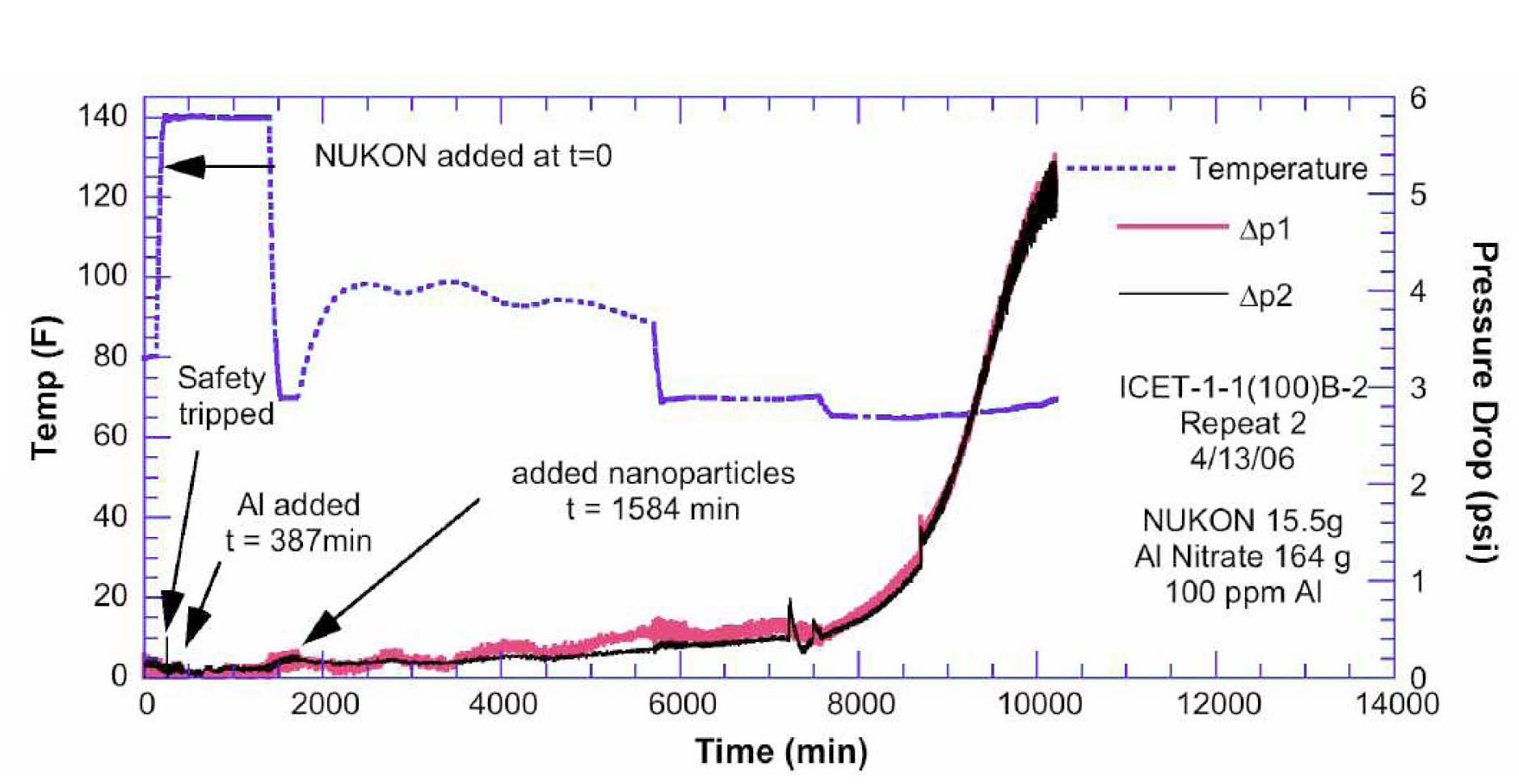
Pressure drops much larger than the expected value from corresponding debris beds in an inert environment have been observed in environments with NaOH buffer for dissolved aluminum levels of 375 and 100 ppm (ICET- 1 environment). These high pressure drops can occur with no visible precipitates. The increases in pressure drops are much larger than those expected due to the small changes in bulk fluid properties, like viscosity, for these solutions. Both tests with 375 ppm dissolved Al concentrations resulted in large pressure drops. No high head losses were observed in two short (8-10 hr) tests with 100 and 200 ppm Al in solution, respectively. However, two longer (6-8 day) tests with 100 ppm Al did result in large pressure drops. The pressure drop history in one of these tests is shown in Fig. 8.
The head loss test in the ICET-5 environment was conducted for ?11 days. No increase in head loss due to precipitate formation was observed. Sodium tetraborate buffers seemed more benign than NaOH or TSP. Interaction of sodium tetraborate with NUKON/CalSil debris mixtures produced much lower head losses than observed in corresponding tests with TSP, although tests were not performed over the full range of CalSil loadings that might be of interest.
Although the final concentration of dissolved Al in ICET 1 was ? 375 ppm, actual plant levels of dissolved Al for the same environments would “scale” with the amount of Al exposed, which is plant specific. In addition, the ICET 1 was run isothermally at 60℃ (120℉), whereas the actual temperatures will vary considerably over the whole course of the accident. The amount of Al exposed to the environment depends strongly on whether the containment sprays are on. To obtain a better estimate of the range of Al that
may be expected in the recirculating water, calculations were performed using more realistic thermal histories for 17 plants [19]. The results suggest that the dissolved Al concentration in ICET-1 is conservative, and most plants with NaOH buffering would be expected to have dissolved Al concentrations at 30 days below 100 ppm. Although comparable time-temperature dissolution history calculations were not performed, the dissolved Al concentration in ICET-5 (i.e., 50 ppm) is probably similarly conservative. Based on the corrosion rates inferred from ICET-5 and the relative amounts of Al in containment compared to ICET-5, most plants with STB buffering would be expected to have dissolved Al concentrations at 30 days below 15 ppm.
A study was initiated before the ICET program to determine the need for a pressurized test loop for ICETs [11]. In addition, to assess whether gelatinous products could form following a LOCA, gain insights into important parameters, and attempt to predict the ICET results, this study performed computer-based thermodynamic simulations of chemical effects. The report NUREG/CR-6873 [11] documents the results of experiments to determine corrosion rates for metals and leaching rates for concrete and fiberglass, which were used as input parameters to the thermodynamic model. Based on the measured corrosion rates, estimated exposed surface area, and exposure time, the thermodynamic simulations indicated that the formation of dominant solid phases was controlled by the presence of NUKON, aluminum, and concrete. The predicted dominant solid phases consisted of potentially amorphous silicate phases such as sodium aluminum silicate (NaAlSi3O8), calcium magnesium silicate (Ca2Mg5Si8O22(OH)2), calcium silicate (CaSiO3), and silica (SiO2). The thermodynamic simulations indicated that, in alkaline simulated containment water at pH 10, corrosion product formation does not differ as high-temperature and -pressure conditions during the initial stages of a LOCA event approach steadystate atmospheric pressure conditions, which could support the validity of ICETs without a pressurized water loop. This study provided initial understanding of the evolution of solution chemistry and possible solid phases. However, as identified in the report, there were assumptions and simplifications to the thermodynamic model. One simplification is that the model does not consider reaction kinetics, which is a common weak point of thermodynamic equilibrium modeling. Another weak point is that the modeling results such as chemical speciation entirely rely on what kinds of information are included in the code database, for example, the reaction equilibrium constant (K) as a function of temperature. In this study StreamAnalyzerⓒ Version 1.2 was used. The modeling results need to be benchmarked by another thermodynamic programs and experimental results. For this purpose, a follow-on study to compare simulation results with ICET observations was conducted by the same authors.
NRC initiated a follow-on study to evaluate the feasibility of utilizing commercially available thermodynamic simulation computer codes to predict the formation of chemical species in a typical post-LOCA PWR containment environment [20]. As an initial step, not only OLI Systems StreamAnalyzer, which had been used in the previous work [11], but also three other computer codes were used: EQ3/6, PHEEQC, and Geochemist’s Workbench REACT. After the code comparison exercise, three of the codes were further examined in more detail. The simulations by three codes were benchmarked to the ICET experiments. After a couple of trial predictions, a complete set of blind and informed predictions was attempted using a single modeling program, PHEEQC, which provided modeling advantages in terms of its flexibility in suppressing the precipitation of specified solids and the ease with which its thermodynamic database could be modified. Because the corrosion/release rates were predetermined and constant over the time period, the code could not address properly the timedependent effect observed in ICETs, such as inhibition effect or metal surface passivation. Results of this study demonstrated that thermodynamic simulation modeling software is broadly useful in assessing the potential effects of post-LOCA interaction on sump strainer blockage. However, its predictive capability is often hindered by insufficient thermodynamic data for relevant phases and
[Table 2.] Containment Materials Classification Summary [12].
Containment Materials Classification Summary [12].
aqueous species in the code database, as well as limitations in the kinetic data for dissolution of reactive materials in the presence of co-dissolving materials. When thermodynamic simulations were refined using ICET data and experimental observations, the predictions broadly agreed with experimental results. Overall, prediction of chemical byproduct concentrations and species is most accurate when the analytical models are properly benchmarked with experimental data.
6. INDUSTRY APPROACH TO EVALUATE CHEMICAL EFFECTS
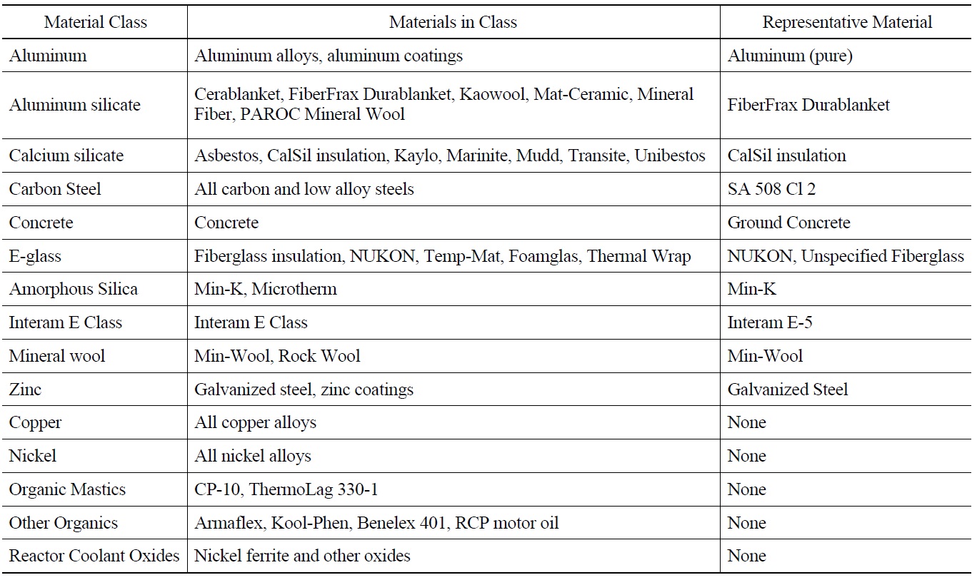
The Westinghouse report WCAP-16530-NP [12,21] is intended to provide a consistent approach for plants to evaluate the chemical effects. The results of this evaluation are intended to provide input on the type and amounts of chemical precipitates that may form post-accident. Based on a containment materials survey for 69 U.S. PWRs, ten material classes were selected for dissolution testing at pH values of 4.1, 8.0, and 12.0, in solutions that contained boric acid (4400 ppm B) with added TSP, STB, and sodium hydroxide. Table 2 shows the summary of containment materials classification. The dissolution tests were conducted at temperatures of 88 and 129℃ (190 and 265℉). Dissolution of each element from representative materials was estimated by Inductively Coupled Plasma (ICP). Precipitation testing was, subsequently, conducted by sampling and cooling the dissolution-test solution. The settling rates and filterability of precipitates were measured which provided baseline data for surrogate chemical precipitate qualification. The WCAP-16530-NP chemical model was developed based on the dissolution testing results. Instructions were provided for preparation of three chemical (surrogate) precipitates.
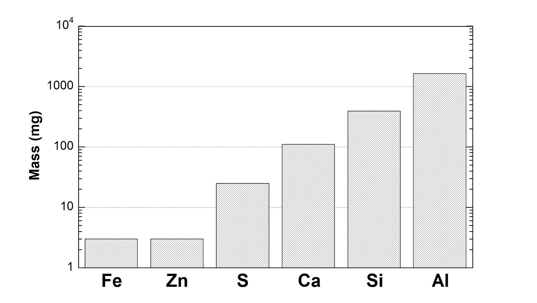
Eleven containment materials were used for the dissolution test: seven insulation materials, plus aluminum, zinc, carbon steel, and ground concrete. The total time for the dissolution testing was 1.5 h at either 88 or 129℃ (190 or 265℉). Elemental analysis was performed using ICP. The ionic material concentration after the equilibration tests was greatest for aluminum, and followed by silicon and calcium in order, as shown in Fig. 9. For this figure, the total mass of each element release in the design matrix dissolution tests was calculated by summing the releases for all times, temperatures, and pH levels. Released mass of Al increased with the solution pH.
Precipitation testing was performed following the dissolution testing. The solution from the dissolution testing was transferred and cooled down, or the solution was mixed with other pH-buffering agents, such as TSP or sodium tetraborate. Precipitate formed in thirteen of the sixty tests performed, and none of the 13 precipitates settled rapidly; thus, all of the precipitates would be expected to be transported to the sump strainer. Chemical composition of the 13 precipitated materials was analyzed by scanning electron microscopy (SEM) and energy dispersive x-ray spectroscopy (EDS). The “best guess” for the precipitates identified six different types: hydrated aluminum oxyhydroxide (AlOOH), sodium aluminum silicate (NaAlSi3O8), calcium aluminum silicate, calcium phosphate, sodium calcium aluminum silicate, and Zn2SiO4 (willemite). Among them, the major chemical precipitates were determined to be aluminum oxyhydroxide, sodium aluminum silicate, and calcium phosphate. Since any TEM or XRD analysis to characterize crystallographic phases was not reported, for example, “aluminum oxyhydroxide (AlOOH)” in WCAP-16530- NP [12] should be considered as a common name for the
aluminum hydroxide family, including the amorphous phase. Precipitate filterability was also assessed, by calculating filter cake coefficients.
For each chemical species, concentration data generated during dissolution testing at specific conditions were used in a regression analysis to develop release rate equations as a function of temperature, pH, and the concentration of that species. Release rate equations were developed for each predominant containment material for each chemical species. It is noted that using the WCAP-16530-NP [12] chemical model for precipitate formation, dissolution of CalSil is greatest at pH values between 5.6 and 8.5, and decreases above 8.5. The chemical model conservatively assumes all dissolved aluminum precipitates as hydrated AlOOH and/or sodium aluminum silicate and all dissolved calcium in phosphate solutions precipitates as calcium phosphate. This assumption appears reasonable for calcium phosphate because of the low solubility, while it is highly conservative for aluminum because ICET 1 and 5 testing [9-10], ANL solubility tests [14], subsequent Westinghouse solubility study [13], and other publications suggest that a significant amount of dissolved aluminum would not precipitate readily but stay in solution as dissolved form or extremely small-size colloidal particle form, which would not induce head loss across the debris bed on the sump strainer.
Since corrosion of aluminum resulted in the greatest mass released during the dissolution testing, the release rate equation for aluminum incorporated into the chemical model needs to be carefully evaluated. The WCAP-16530-NP chemical model underestimates the aluminum release for the active corrosion part of ICET 1. However, since the 30-day total aluminum release is conservative compared with ICET 1 and the WCAP-16530-NP chemical model assumes 100% precipitation of released aluminum, using this chemical model to estimate the 30-day total mass of chemical precipitates for chemical-effects head loss testing appears to be reasonable, if the total precipitates are added at the beginning of the head loss testing.
The WCAP-16530-NP chemical model assumes that sodium aluminum silicate would precipitate first if there is dissolved silicate, and then the remaining aluminum would precipitate as AlOOH, which is based on the thermodynamic analysis in NUREG/CR-6873 [11]. As discussed in a previous section, the thermodynamic analysis suggested sodium aluminum silicate precipitation if NaOH, aluminum, NUKON, and concrete are present together. This analysis might be correct but needs to be carefully evaluated because the ICETs did not indicate any formation of sodium aluminum silicate precipitate, and thermodynamic modeling is highly dependent on the adequacy of its thermodynamic database. However, if the filterability of the sodium aluminum silicate is comparable with that of AlOOH, as claimed in this Westinghouse report, the assumption of sodium aluminum silicate formation in the model would be acceptable. Comparison of two precipitates in terms of filterability was performed by ANL head loss testing [22] and is further discussed in the following sections.
The chemical model is based on single effects and does not consider multiple materials effect. The ICETs indicated some multiple materials effects, such as Al corrosion inhibition by dissolved silicate (ICET 4) and Si release inhibition by dissolved Al (ICET 5). However, the enhancement of release rates by the multiple materials effect was not evidenced. Therefore, the chemical model based on single effects appears reasonable.
6.3 Surrogate Chemical Precipitates
WCAP-16530-NP provides instructions on preparing chemical surrogates for three major chemical precipitates (AlOOH, sodium aluminum silicate, and calcium phosphate) and qualification criteria for the settling rate of these surrogates. If the settling rate is too high, the prepared surrogate should not be used in head loss testing. The way to prepare surrogates is relatively simple and convenient to follow, but an identification analysis to confirm the surrogate’s crystallographic phases was not provided. Rough estimation for surrogate size is available, but size distribution measurements in solution are needed, for example, by using a laser light scattering method. Argonne letter reports suggest that the AlOOH surrogate in WCAP-16530-NP is most likely amorphous [23]. To prepare AlOOH surrogate, aluminum nitrate was added into water, followed by sodium hydroxide. Since aluminum would precipitate in alkaline water under actual post-accident sump conditions, it would be more prototypical if sodium hydroxide were added into water first, followed by aluminum nitrate. This reverse procedure might raise other issue because of a strong caustic condition by dissolved sodium hydroxide. As long as the AlOOH surrogate is efficient in inducing head loss across the debris bed, this procedural modification may not be necessary.
Important containment material classes were selected on the basis of survey results. Eleven representative materials were tested for dissolution and precipitation. From these tests, three major chemical precipitates were identified: hydrated AlOOH, sodium aluminum silicate, and calcium phosphate. Settling rates and filterability were measured for formed precipitates. However, the measurement of filterability, in this study, was not reliable since the model used to calculate the filter cake coefficient was determined by calculating a precipitate mass measured after drying. These calculations assumed the same degree of hydration for different batches of precipitate and different precipitates. This may not be a valid assumption. The chemical model was developed from dissolution testing and can predict total precipitate mass during the 30-day mission time under plantspecific conditions. The model assumes that all dissolved aluminum would precipitate, and all released calcium would precipitate in phosphate solution, which is highly conservative for aluminum precipitation. The WCAP-16530-NP report provides instructions on preparing each chemical surrogates and qualification criteria for the settling rate. The chemical surrogates were poorly characterized in terms of crystallographic phases and particle size distributions. However, if these surrogates are highly efficient in inducing head loss across the debris bed, detailed surrogate characterization might not be necessary.
Several industry- or NRC-sponsored researches were performed to further evaluate the methods or test results in WCAP-16530-NP. Some NRC-sponsored tests focused on a more detailed evaluation of the dissolution characteristics of specific insulation materials and concrete [24]. An industry-sponsored investigation was performed to further evaluate the inhibition of corrosion in aluminum and aluminum alloys in the presence of silicates and phosphates at 38 and 93℃ (100 and 200℉) [13]. The solubility was also measured for sodium aluminum silicate, aluminum oxyhydroxide, and calcium phosphate. Another industrysponsored effort was to evaluate alternative pH buffers to the most common ones: NaOH and TSP [25]. Two buffers, sodium metaborate (SMB) and STB, were recommended based on the results from a series of testing including precipitation formation, dissolution rate, corrosiveness, etc. Although several screening testing was performed, more critical testing, specifically the effect of precipitates on the strainer head loss, is needed to fully qualify the recommended buffers. It is noted that the reported threshold values for precipitate formation from dissolved aluminum in STB (177 ppm) are significantly higher than those observed during longer term bench testing and head loss testing at ANL [23] and ICET 5 [9]. In the following sections, studies on three topics (WCAP chemical surrogates [22,26], Al chemistry [27-28], and aluminum hydroxide precipitation [14,29]) are reviewed more in detail.
7.1 Follow-on Study on WCAP-16530 Chemical Surrogates
Since the WCAP-16530-NP provided little information on the characteristics of the chemical surrogates and their effect on the head loss, additional testing was performed at ANL [22,26]. ANL conducted vertical loop head loss tests to evaluate precipitate filterability and bench-type tests and to investigate precipitate characteristics such as particle size and settlement rate and solubility. Specific precipitates that were evaluated included aluminum oxyhydroxide (AlOOH) and sodium aluminum silicate (SAS) prepared according to the instructions of the WCAP-16530-NP [12].
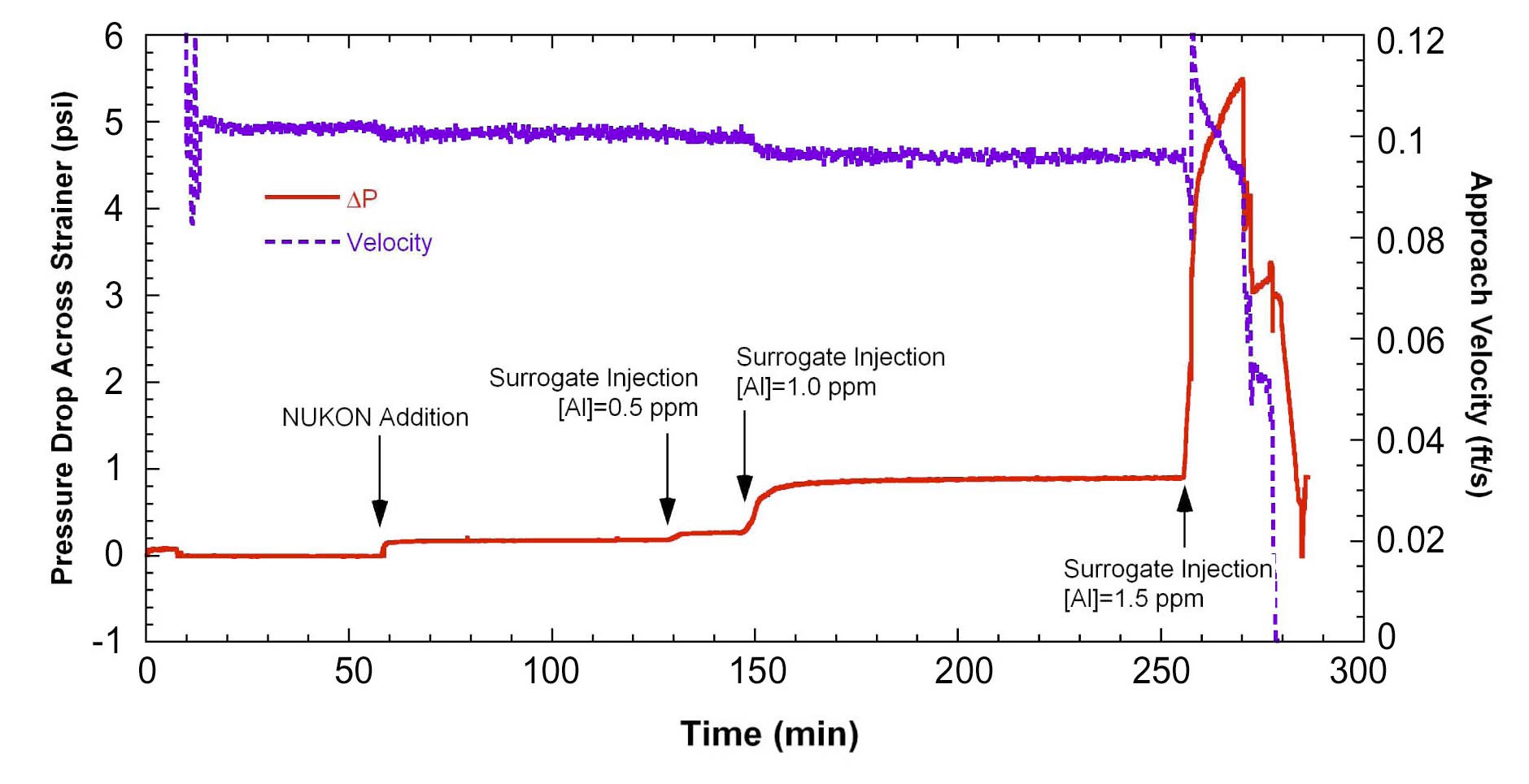
ANL had previously performed a vertical head loss loop test with the WCAP-16530-NP AlOOH precipitate [18,23]. An additional head loss test using the WCAP- 16530-NP AlOOH surrogate but at lower concentration was performed [22,26]. In the ANL loop, only 1.5 ppm Al equivalent of surrogate (29.6 g/m2) can completely plug a glass fiber bed, as shown in Fig. 10. The test confirmed that the AlOOH surrogate is highly effective in increasing the head loss across a glass fiber bed, which is consistent with that of the earlier ANL head loss test with 5 ppm Al [23]. Tests with the SAS surrogate showed that it is not quite as efficient as the WCAP AlOOH surrogate in increasing head loss. At low levels, the SAS surrogate tends to dissolve, especially in high purity water. However, in tap water, only 2 ppm Al equivalent SAS surrogate (172 g/m2) is needed to generate a significant head loss. Therefore, both surrogates are quite effective in the increase of head loss with a glass fiber debris bed.
The median particle sizes of the WCAP-16530-NP AlOOH surrogates were 13-72 μm, depending on the Al concentration in the mixing tank. For the same mixing concentration, the particle sizes of the SAS surrogate are larger than those of the AlOOH surrogate. The settling rates of the surrogates are strongly dependent on particle size, and the rates are reasonably consistent with those expected from Stokes Law or colloid aggregation models [22,26]. The particle size distribution of these surrogates was significantly shifted by ultrasonic vibration (i.e. the size became smaller) suggesting that the binding energy between particles in surrogates is relatively low. Compared with the precipitate size formed in the ICET-1 solution at room temperature, the WCAP-16530-NP AlOOH surrogates are highly flocculated, but the total Al concentrations are different (i.e., 375 ppm vs. 1000 ppm). It was also shown that the particle size distributions of various surrogates are universal, consistent with the predictions of reactionlimited colloid aggregation theory [26].
7.2 Al Chemistry and Corrosion Products
Previous ANL head loss tests for aluminum hydroxide (Al(OH)3) precipitates have been performed with surrogates
proposed by the WCAP-16530-NP [22-23] or by forming precipitates in situ with aluminum nitrate, Al(NO3)3 [18] or sodium aluminate [22,26] as the source of dissolved Al. In a post-LOCA environment, however, the precipitates would form in situ with the source of the Al, dissolution of Al by corrosion of Al alloys. To resolve this issue, additional head loss tests were performed with the source of Al, corrosion from submerged Al alloy plates [27-28]. The head loss characteristics were compared with those obtained with WCAP-16530-NP precipitates and with precipitates formed in situ as a result of chemical addition.
The head loss tests were performed with 6061 Al alloy and “commercially pure” 1100 Al plates immersed in borated solution. The Al release rate from 6061 Al alloy in borated water at a pH=9.35 (at room temperature) and 60℃ (140℉) with a flow rate of 0.03 m/s (0.1 ft/s) was similar to predictions based on data from bench-top tests and low-flow rate tests with 1100 and 3003 Al alloys. However, the Alloy 1100 corrosion rate was higher than the predictions based on data from bench-top tests, suggesting the corrosion rate of Al alloys is dependent on the flow rate.
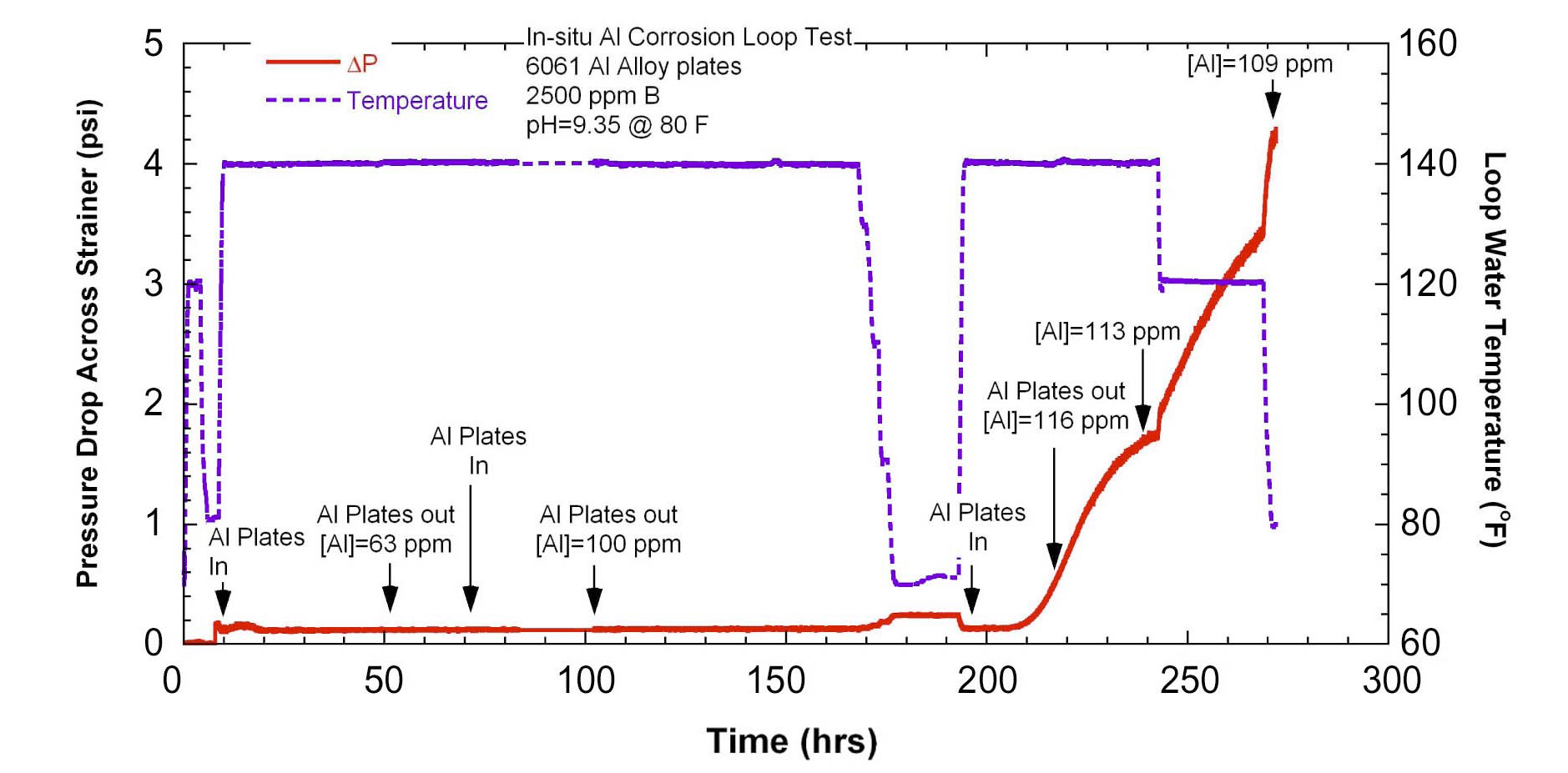
Figure 11 shows the pressure drop across the debris bed and temperature as a function of time. Alloy 6061, when allowed to corrode in a flowing loop, created a significant head loss at Al concentration of 116 ppm with a pH of 9.35 and 60℃ (140℉). An additional increase in the head loss was observed when the temperature was lowered. Posttest examination revealed that grayish black particles were trapped in the glass fiber bed. Stagnant bench-top corrosion tests with Alloy 6061 also showed grayish black particles, which were released from the coupon surfaces rather than being generated as a precipitate from the solution. Based on microscopic analyses, it was concluded that the grayish black particles were intermetallic particles present in the alloy that were released by corrosion of the alloy matrix. The intermetallic particles were primarily ternary compounds (FeSiAl) ranging in size from a few tenths of a micrometer to 10 μm. The ANL bench-top tests and other loop tests showed that the solubility limit for Al(OH)3 at pH=9.35 (at room temperature) and 60℃ (140℉) is significantly greater than 116 ppm Al. This result indicates
that the head loss at 60℃ was induced by the intermetallic particles present in the 6061 Al alloy. As the temperature of the loop was decreased, additional head loss occurred due to the formation of Al(OH)3 at lower temperatures (i.e. the dissolved aluminum exceeded its concentration limit at the lower temperature).
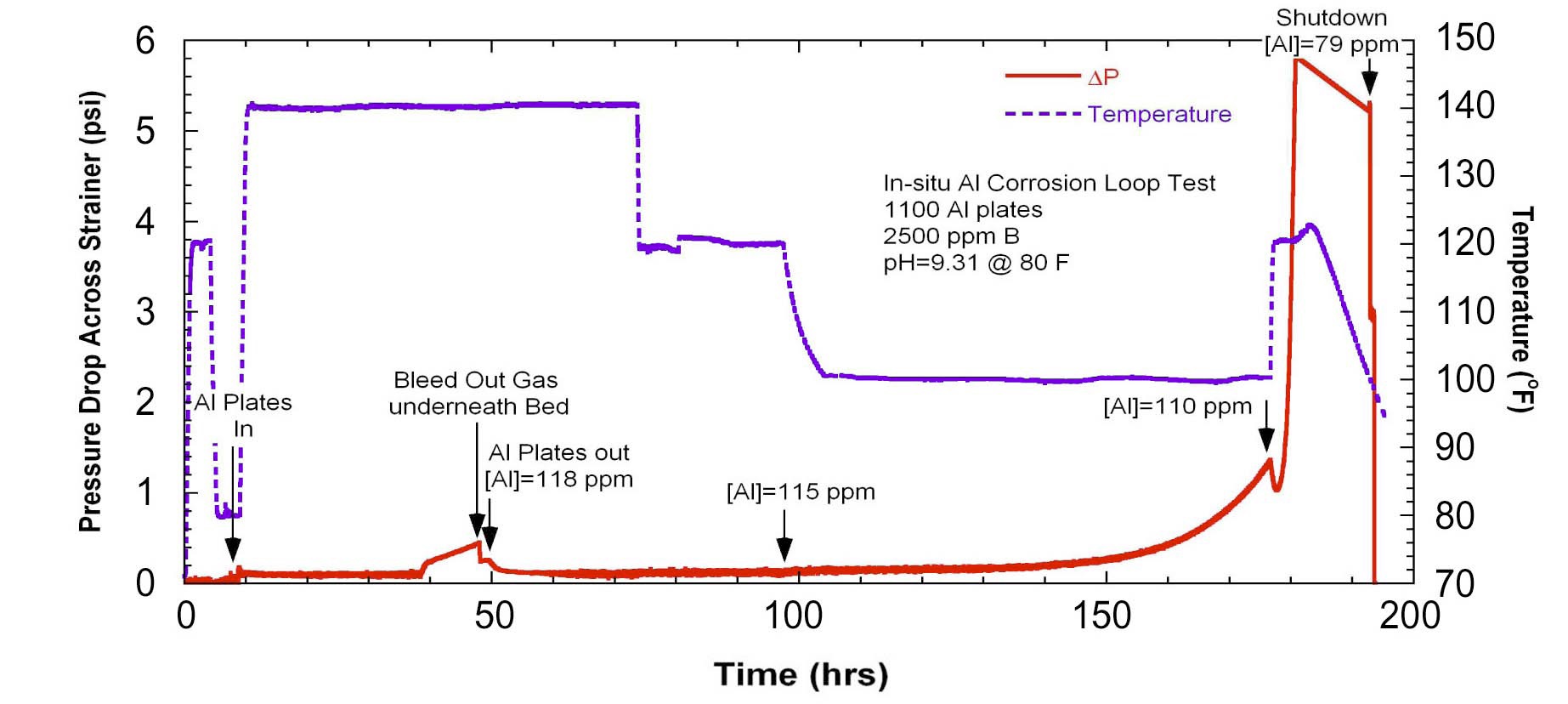
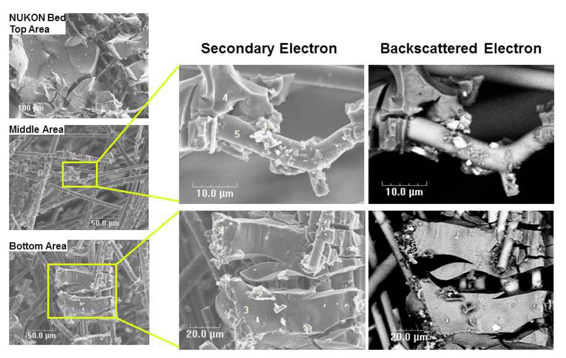
Another head loss test was conducted with 1100 Al plates. Figure 12 shows the pressure drop and temperature variation with time. With an Al concentration of 118 ppm in the loop from corrosion of 1100 Al plates, no significant increase in head loss was observed at 60℃. Post-test examination for the glass fiber bed and bench-top test results confirmed that Fe-Cu enriched intermetallic particles were present in the 1100 Al, which were released and captured in the bed during the loop test. The differences in head loss behavior associated with the intermetallic particles may be attributed to the size difference of the intermetallic particles. The intermetallic particles in 6061 Al alloy were typically larger than those in 1100 Al alloy. At the Al concentration of 118 ppm no significant increase in head loss was observed in the 1100 Al test until the temperature was decreased to 38℃ (100℉). This increase appeared to be induced by Al hydroxide precipitation, not by intermetallic particles. Once the head loss began to increase, a rapid increase in head loss was observed, even though the temperature was increased from 38 to 49℃ (100 to 120℉). As shown in Fig. 13, the glass fibers in the debris bed was coated with Al hydroxide precipitates, and at some areas thick precipitation layers were also observed. In addition to the Al hydroxide precipitates, intermetallic particles were identified on the fiber or precipitates surfaces, which is more noticeable in the backscattered electron images in Fig. 13.
The vertical-loop head loss tests for Al corrosion with 6061 and 1100 Al plates suggest somewhat lower solubility than the chemical Al tests. This difference may be due to heterogeneous nucleation of Al hydroxide on intermetallic particles and/or on the surfaces of preexisting Al hydroxide precipitates. This Al solubility issue is further discussed in the following section. The test results suggest that the contribution from corrosion of an Al alloy to increased head loss would depend on its microstructure (i.e., the size distribution and number density of intermetallic particles), as well as its Al release rate. The increase in head loss due
to in situ precipitation of Al(OH)3 observed in these tests seems reasonably consistent with that expected from the addition of corresponding amounts of the WCAP-16530- NP surrogate. Per unit mass of Al removed from solution, the WCAP-16530-NP surrogate appears somewhat more effective in increasing head loss than the Al(OH)3 precipitates formed in situ by corrosion or chemical addition of Al, and thus it gives conservative estimates of the head loss due to the precipitation of a given amount of Al from solution. However, in choosing the amount of surrogate that should be used, consideration should be given to the potential for additional head losses due to intermetallic particles and the apparent reduction in the effective solubility of Al(OH)3 when intermetallic particles are present.
7.3 Al Hydroxide Precipitation Limit
One of the significant findings in the ICETs was that Al alloy was most susceptible to corrosion under the test conditions [16], particularly in higher pH solutions, which would be observed in plants using sodium hydroxide or sodium tetraborate. Several Al dissolution/solubility testing suggested that dissolved aluminum in the sump water may not cause a noticeable head loss to some extent, which can be considered as a solubility limit. Since the solubility concept for Al precipitation as a function of pH and temperature could significantly affect the possibility of head loss through a sump strainer at a given Al concentration, it is desirable to obtain a reasonable estimation on the Al hydroxide precipitation limit under a post-LOCA sump chemical environment.
Long-term Al(OH)3 solubility tests were conducted in solutions containing 2500 ppm B, and 40-98 ppm Al, using aluminum nitrate or sodium aluminate as the Al source [14,29]. The solution temperature was cycled to obtain a temperature history more representative of ECCS temperatures during operation in the recirculation mode after a LOCA in PWR. Precipitates were observed to form as fine, cloudy suspensions, which showed very little tendency to settle. Under certain conditions, however, they formed as flocculated precipitates, which appeared on the inner surface of the test flasks. Based on the prior ANL head loss tests with chemical surrogates [22], the flocculated precipitates would be expected to cause significant increases in head loss in glass fiber beds. Very fine precipitates associated with the cloudy solutions would be less effective for causing head loss in the ANL vertical loop with a fiberglass-only bed, but could cause a different head loss response for different bed conditions (e.g., in cases where pore sizes are smaller than in fiberglass-only beds). The flocculation tendency of the precipitates can be qualitatively explained in terms of ionic strength and solution pH according to a colloidal stability theory referred as the Derjaguin, Landau, Verwey and Overbeek (DLVO) theory, considering van der Waals and electrostatic inter-particle potentials [29].
The thermal cycling intermittently introduced during the long-term solubility testing did not induce rapid precipitation. Thermal cycling did not cause either instantaneous Al hydroxide precipitation from clear solution or additional precipitation from already precipitated solution. A typical thermal cycling time of 30 min might not be sufficient for incubation of Al hydroxide precipitate in the temperature range (60-27℃) of interest. However, this result does not necessarily exclude the possibility that precipitation would be enhanced by the thermal cycling at a heat exchanger because one ANL loop head loss test (see Fig. 12) showed that the head loss decreased but rapidly increased again after the temperature increase from 38 to 49℃ (100 to 120℉). More systematic experiments are needed to evaluate the issue of temperature cycling.
A degree of supersaturation
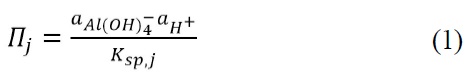
where
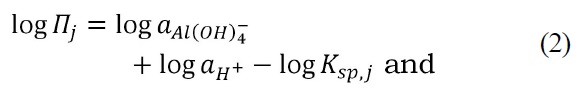
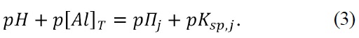
In these expressions,
Since using
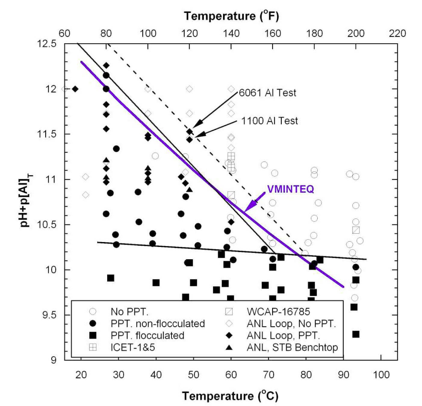
Based on the solubility data summarized in Fig. 14, bounding estimates of aluminum solubility (or Al hydroxide precipitation) in alkaline environments containing boron can be obtained. The bounding curves were drawn based on engineering judgment. The bounding line between flocculation and non-flocculation is shown in Fig. 14, which is less sensitive to temperature. Two bounding lines are proposed for the boundary between precipitation and non-precipitation (see solid and dashed lines in Fig. 14). The lower solid line bounds all data except for the two data points from the Al corrosion loop tests [27] and one other data point from another loop test based on chemical
additions. Shifting the solubility estimate upward to bound the data points from the loop tests gives the dashed line. Quantitative equations for each bounding line are available in literatures [29]. The Al solubility values based on the dashed bounding line are more conservative, i.e., they predict a lower value for the amount of Al that can be present before precipitation occurs.
Most of the available high temperature (>60℃) data come from long-term Al solubility tests at ANL. The test solution was alkaline or near neutral and composed of boric acid and sodium hydroxide. Aluminum was added as sodium aluminate. The temperature history was to be representative of the temperature of the reactor coolant as it passes through the core, a heat exchanger, and the sump after a LOCA. The test durations at higher temperatures (>60℃) are relatively short, no more than one day at each temperature. The relatively short test times and the presence of boric acid in the test solution should be kept in mind when applying the proposed Al solubility curves at relatively high temperatures (>60℃) or in boron-free environments. In a boron-free environment the Al solubility may decrease significantly.
8. ADDITIONAL ISSUES ON CHEMICAL EFFECTS
The NRC convened an external peer review panel to review the NRC-sponsored research and to identify and evaluate additional chemical phenomena and issues that were either unresolved or not considered in the original NRC-sponsored research [31]. A phenomena identification and ranking table (PIRT) exercise was conducted to support this evaluation in an attempt to fully explore the possible chemical effects that may affect ECCS performance during a hypothetical LOCA. The PIRT was not intended to provide a comprehensive set of chemical phenomena within the post-LOCA environment. Rather, these phenomena should be combined with important findings from past research and informed by ongoing research results.
The PIRT panel identified a number of significant chemical phenomena. These phenomena pertain to the underlying containment pool chemistry; radiological considerations; physical, chemical, and biological debris sources; solid species precipitation; solid species growth and transport; organics and coatings; and downstream effects. Several of these phenomena may be addressed using existing knowledge of chemical effects in combination with an assessment of their implications over the range of existing generic or plant-specific post-LOCA conditions. Other phenomena may require additional study to understand the chemical effects and their relevance before assessing their practical generic or plant-specific implications.
Experimental testing and other studies have been completed to determine the effect of cooling water composition, debris sources, and materials corrosion on the nature of the debris, presuming no fuel cladding failure. However, ten further topics related to chemical effects were identified that deserve additional consideration [32]. The ten topic areas are radiation effects (particularly on material corrosion), differences in concrete carbonation between tested systems and existing containment structures, effects of alloy variability between tested and actual materials, galvanic corrosion effects, biological fouling, co-precipitation, other synergistic solids formation effects, inorganic agglomeration, crud release effects (types and quantities), retrograde solubility and solids deposition, and organic material impacts. Sufficient data or prior related studies were available to sufficiently address some of the questions raised in the 10 topic areas. However, among these ten broad areas, topics that merit additional consideration were also identified. The topic with the greatest perceived influence on ECCS performance is the interaction of organic materials (lubricants and coatings) with inorganic solids. The effects of radiolysis on redox potential and thus metal corrosion have the next most influence. Of similar influence are the effects of biological growth in the post-LOCA system and the impacts of dried borate salts on hot fuel cladding and reactor pressure vessel materials. Of lesser, but not insignificant, influence are galvanic corrosion, inorganic agglomeration, and crud release effects on increasing and altering solids delivered to the post-LOCA coolant. Changes in concrete carbonation and differences in alloy corrosion rates were judged to have minor impacts on ECCS functionality.
The NRC staff conducted an initial evaluation of phenomena identified by the peer review panel, which are summarized in NUREG-1918 [31], and reduced the list to those phenomena that can be potential contributors to ECCS performance degradation. The final list is consisted of 41 items and tabulated in an NRC evaluation report [33]. The NRC staff grouped these phenomena into 10 topic areas, which were subsequently evaluated and reported in NUREG/CR-6988 [32]. A team of NRC staff further evaluated these phenomena using existing knowledge and the findings from the industry and NRC-sponsored research. The staff’s evaluation of the outstanding issues concluded that the implications of these issues are either not generically significant or are appropriately addressed, although several issues associated with downstream in-vessel effects remain. The remaining issues are summarized below [33].
The deposition of precipitates on reactor fuel and its effects on core cooling
The effect of physical and chemical debris contained within the core on the ability of the coolant to remove heat from the core
The effect of debris settling on the grid straps to block flow and prevent heat transfer from the fuel cladding
The potential for particulate settling on the grid straps to block flow and prevent heat transfer from the fuel cladding
Potential chemical effects on the head loss across the debris-loaded sump strainer under a post-LOCA condition, raised by NRC ACRS, were experimentally evidenced by small-scale bench tests [7], integrated chemical effects tests [9], and vertical loop head loss tests [18]. Industry’s efforts to address the chemical effects were documented in WCAP-16530-NP [12,21]. Three main precipitates were identified by WCAP-16530-NP: calcium phosphate, aluminum oxyhydroxide, and sodium aluminum silicate. The former two precipitates were also identified as major chemical precipitates by the ICET tests. The assumption that all released calcium would form precipitates is reasonable. CalSil insulation needs to be minimized especially in a plant using TSP buffer, which has already been implemented by licensees. The assumption that all released aluminum would form precipitates appears highly conservative because ICETs [9-10], and other studies suggest substantial solubility of aluminum at high temperature [14,29] and inhibition of aluminum metal corrosion by silicate or phosphate [13]. The buffer STB tends to allow even higher solubility of aluminum [13,18,23]. This buffer was estimated as a good candidate to replace NaOH [25].
The WCAP-16530-NP [12,21] is conservative in terms of not only aluminum solubility but also filterability of surrogates. The AlOOH and SAS surrogates are quite effective in increasing the head loss across the debrisloaded bed and more effective than the prototypical aluminum hydroxide precipitates generated by in-situ aluminum corrosion. The NRC Safety Evaluation of WCAP-16530 (NRC-SER-2007b) also notes that some of the conservative assumptions in the WCAP-16530-NP methodology are the basis for accepting other chemical effects uncertainties. In the plant-specific surrogate case, aluminum hydroxide precipitates were deflocculated by dissolved silicates, which led to fine particle size (100-300 nm) and poor filterability by a glass fiber debris bed [22]. This result suggests that preparation procedures and test conditions for the chemical surrogates different from the one proposed by WCAP- 16530-NP need to be carefully evaluated so that any nonconservatism can be avoided.
Modeling efforts to predict possible chemical precipitates formed under a post-LOCA sump water condition were documented [11,20]. Thermodynamic modeling is limited by available thermodynamic database and cannot predict effects related to reaction kinetics, such as aluminum inhibition/passivation. Thermodynamic modeling, therefore, needs to be benchmarked by experimental results.
NRC conducted an exercise of the phenomena identification and ranking table (PIRT) between March 2006 and June 2006 to identify additional chemical effects that may affect the performance of the ECCS [31]. The PIRT panelists identified and evaluated over 100 chemical effects phenomena. These phenomena pertain to the underlying containment pool chemistry; radiological considerations; physical, chemical, and biological debris sources; solid species growth and transport; organics and coatings; and downstream effects. As identified in NUREG/CR-6988 [32], there appears to be some unresolved potential issues related to GSI-191 chemical effects, such as organic/inorganic interaction, the effect of radiolysis, the effect of biological growth, and the impacts of dried borate salt on hot fuel cladding. The NRC staff further evaluated 41 outstanding issues including those identified in NUREG/CR-6988. They concluded that the implications of these issues are either not generically significant or are appropriately addressed, although several issues associated with downstream invessel effects remain.

![Ratio of Measured Head Loss with and without Chemical Precipitates as a Function of Metal ion Concentration [7].](http://oak.go.kr/repository/journal/12382/OJRHBJ_2013_v45n3_295_f001.jpg)
![Test Parameters of the ICET Series [9].](http://oak.go.kr/repository/journal/12382/OJRHBJ_2013_v45n3_295_t001.jpg)
![Measured Aluminum Concentrations in Tests 1 and 5 [9].](http://oak.go.kr/repository/journal/12382/OJRHBJ_2013_v45n3_295_f002.jpg)
![Measured Calcium Concentrations in Tests 1-5 [9].](http://oak.go.kr/repository/journal/12382/OJRHBJ_2013_v45n3_295_f003.jpg)
![Measured Silicon Concentrations in Tests 1-5 [9]. Note that Although Expressed in NUREG/CR-6914 [9] as Silica (SiO2) Concentration, it is Probably Silicon (Si) Concentration because that is what Would be Directly Measured by ICP.](http://oak.go.kr/repository/journal/12382/OJRHBJ_2013_v45n3_295_f004.jpg)
![Schematic Diagram of ANL Vertical Head Loss Test Loop [18].](http://oak.go.kr/repository/journal/12382/OJRHBJ_2013_v45n3_295_f005.jpg)
![Fiber Debris Bed Approach Velocity and Differential Pressures Across the Strainer as a Function of Time [18]. Note that ICET-3-10 (#10) was Tested with TSP but ICET-3-11 (#11) was Tested without TSP. 1 psi=6.895 kPa; 0.1 ft/s=0.03 m/s.](http://oak.go.kr/repository/journal/12382/OJRHBJ_2013_v45n3_295_f006.jpg)
![Fiber Debris Bed Approach Velocity and Differential Pressure Across the Strainer as a Function of Time for Test ICET-3-18 with TSP [18]. 1 psi=6.895 kPa; 0.1 ft/s=0.03 m/s.](http://oak.go.kr/repository/journal/12382/OJRHBJ_2013_v45n3_295_f007.jpg)
![Fiber Debris Bed Approach Velocity and Differential Pressure Across the Strainer as a Function of Time for a Head Loss Test with 100 ppm Al Concentration [18]. 1 psi=6.895 kPa.](http://oak.go.kr/repository/journal/12382/OJRHBJ_2013_v45n3_295_f008.jpg)
![Containment Materials Classification Summary [12].](http://oak.go.kr/repository/journal/12382/OJRHBJ_2013_v45n3_295_t002.jpg)
![Comparison of Total Mass Released during Dissolution Testing by Element [12].](http://oak.go.kr/repository/journal/12382/OJRHBJ_2013_v45n3_295_f009.jpg)
![Pressure Drop and Strainer Approach Velocity vs. Time in a Loop Test using the WCAP16530-NP Aluminum Hydroxide Surrogates [22]. 1 psi=6.895 kPa; 0.1 ft/s=0.03 m/s.](http://oak.go.kr/repository/journal/12382/OJRHBJ_2013_v45n3_295_f010.jpg)
![Pressure Drop and Loop Water Temperature vs. Test Time using 6061 Al Plates with 2500 ppm B, Initial pH=9.35 Solution, and Temperature of 80℉ [27]. 1 psi=6.895 kPa.](http://oak.go.kr/repository/journal/12382/OJRHBJ_2013_v45n3_295_f011.jpg)
![Pressure Drop Across the Strainer and Temperature vs. Test Time using 1100 Al Plates [27]. 1 psi=6.895 kPa.](http://oak.go.kr/repository/journal/12382/OJRHBJ_2013_v45n3_295_f012.jpg)
![SEM Micrographs of the Glass Fiber Debris Bed Internal after the Head Loss Testing with 1100 Al Plates [27].](http://oak.go.kr/repository/journal/12382/OJRHBJ_2013_v45n3_295_f013.jpg)
![Al Hydroxide Precipitation Map in the ‘pH+p[Al]T’ vs. Temperature Domain Based on ANL’s Bench Top and Loop Test Data and Literature Data [29].](http://oak.go.kr/repository/journal/12382/OJRHBJ_2013_v45n3_295_f014.jpg)