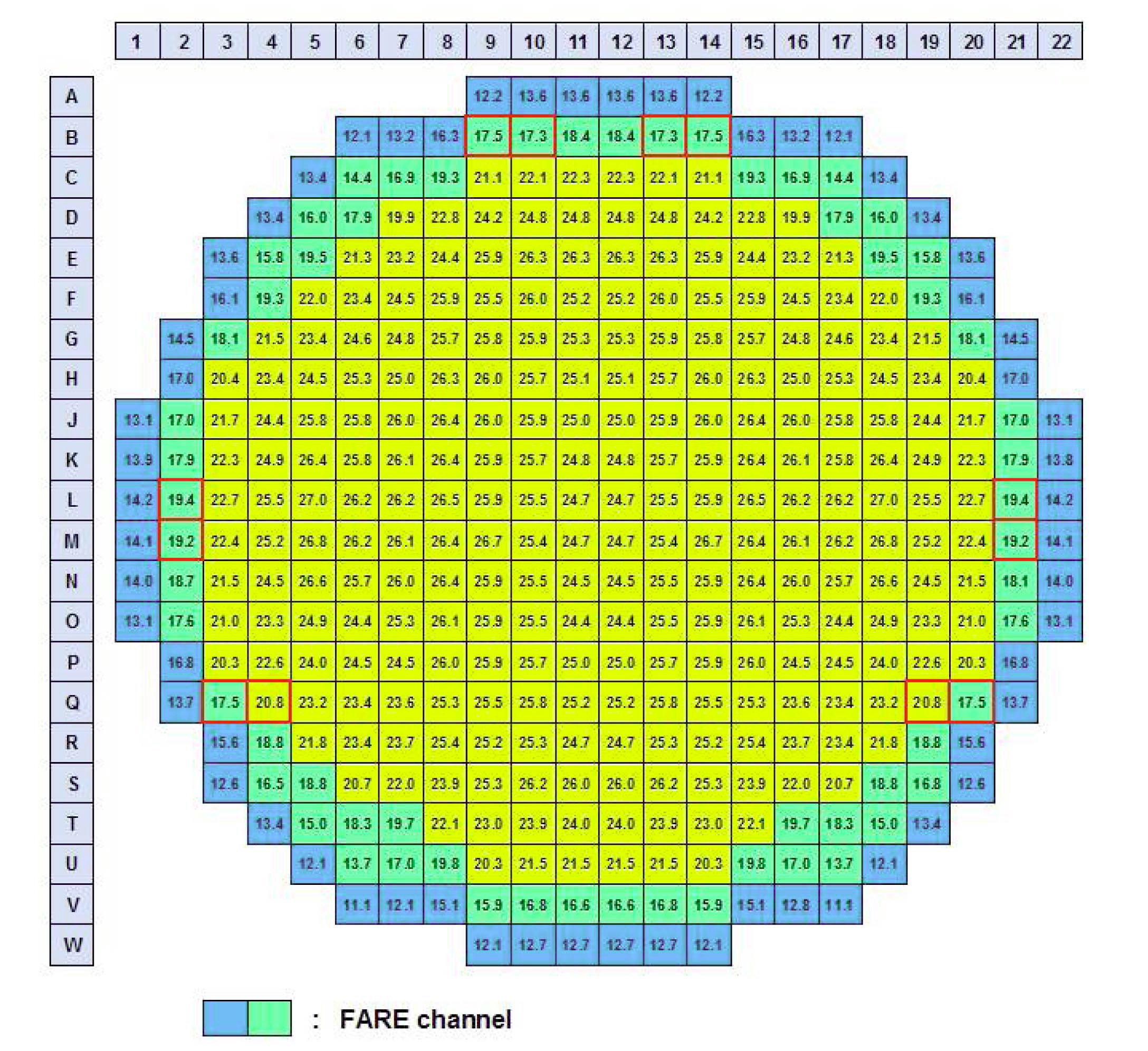
In Canada Deuterium Uranium (CANDU)-type nuclear power plants, the reactor is composed of 380 fuel channels (Fig. 1). Refueling is performed on one or two channels on a daily basis. During the refueling operation, two remote controlled Fueling Machines (F/M) are attached to a designated fuel channel and carry out the refueling job. The upstream F/M inserts new fuel bundles into the fuel channel while the downstream F/M discharges spent fuel bundles. At the time of refueling, the fluid force of the cooling water inside the channel is exploited. Specifically, new fuel bundles inserted upstream of the fuel channel are moved downstream by the fluid force of the cooling water, and spent fuel bundles are pushed out. Through this process, refueling is completed. Among the 380 fuel channels, outer rows 1 and 2 (called FARE channels) make it impossible to perform refueling with only the internal fluid force because of the low flow rate of the channel cooling water. Therefore, a Flow Assist Ram Extension (FARE) tool, a refueling aid, is used for these channels in order to compensate for the insufficient fluid force. The FARE tool causes flow resistance, thus allowing the fuel to be moved down with the flow of cooling water.
The existing FARE tool can perform refueling in Korean domestic plants; however, the coolant flow rate decreases to below 80% of the normal flow for some time during refueling. A Flow rate below 80% of the normal flow causes a low flow rate alarm signal in the plant operation. A flow rate below 80% of the normal flow may cause difficulties in the plant operation because of the increase in the coolant temperature of the channel. An improved FARE tool is needed to solve this issue with the existing FARE tool.
2. FARE TOOL STRUCTURE AND CHARACTERISTICS
2.1 Structure of the FARE Tool
Figure 2 shows the FARE tool structure [1], [2]. A FARE tool is composed of a fuel adapter, flow orifice, sleeve, and stem. The total length of a FARE tool is equal to that of two fuel bundles (about 1 m), and its external diameter is equal to that of a fuel bundle. The front part of the FARE tool includes a fuel adapter that contacts the end plate of the fuel bundle (Fig. 2-①), and forms three concentric circles such that the end plate constantly supports the fuel bundle. The fuel adapter and the flow orifice are connected by a Zircaloy-2 tube (Fig. 2-②). The Zircaloy-2 tube has holes that allow the cooling water to flow. The flow orifice is composed of an orifice housing (Fig. 2-③), a spring holder (Fig. 2-⑫), a ring orifice (Fig. 2-④), and a spring (Fig. 2-⑪). The ring orifice is closed by the spring (Fig. 2-⑪).
The orifice housing has four bypass slots. The cooling water flows through the four slots when the ring orifice moves. The major portion of flow resistance of a FARE tool occurs at the ring orifice composed of the four rings.
2.2 Characteristics of Existing FARE Tool
Figure 3 shows the variation of differential pressure (pressure drop, ΔP ) that occurs in the existing FARE tool at several different initial flow rates. These results were measured using a CANDU refueling test apparatus (Fig. 4). This apparatus was installed in the Korea Electric Power Research Institute in Deajeon for this FARE tool experiment. The differential pressure is the source of the force pushing fuel inside the channel from upstream to downstream.
As shown in the figure, the pressure drop shows a sharp upward trend when the initial flow is increased from 0 to 5.0 kg/s. The pressure drop then shows a steady upward trend when flow is increased beyond 5.0 kg/s. When the flow rate is 5.0 kg/s and over, the FARE tool’s ring orifice is opened. This opening forms a flow path to the four bypass slots, which mitigates the increase in pressure drop.
The FARE tool is used in the refueling of outer rows 1 and 2 of the fuel channels. In these channels, the coolant flow range is between 11 and 20 kg/s. The pressure drop occurring in this range is from 450 to 480 kPa, as shown in Fig. 3.
During refueling, fuel bundles can be pushed downward when the fluid force of the FARE tool exceeds the frictional force of the 12 fuel bundles inside the channel. The frictional force of one bundle of fuel is 0.6 (frictional coefficient, AECL°Øs test result [3])×23.27 kg (the weight of one bundle of fuel) 9.8 m/s2 = 137 N. Thus, a force of 1644 N is required to push out the 12 bundles of fuel for refueling.
When the differential pressure of the FARE tool, shown in Fig. 3, is converted to fluid force, the lowest coolant flow rate of the FARE channel (11.0 kg/s) exhibits a fluid force of 3700 N. When the flow rate is 20.0 kg/s, the fluid force is 3900 N. This means that the force necessary for refueling can be generated by the FARE tool.
3. ANALYSIS OF FLOW RATE DECREASE PHENOMENA DUE TO THE FARE TOOL
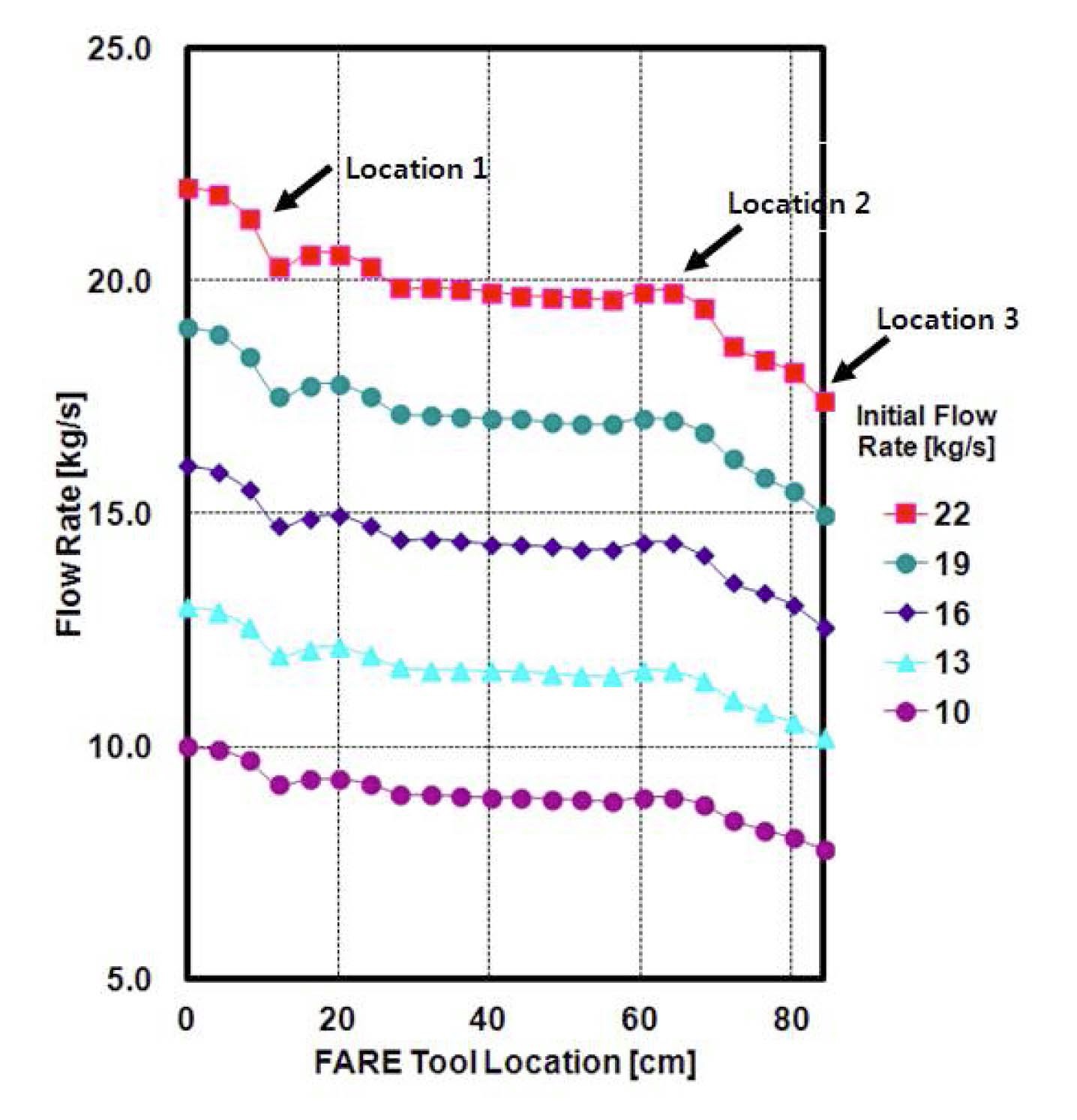
Figure 5 shows flow rate changes corresponding to the FARE tool location for several initial flow rates: 10, 13, 16, 19, and 22 kg/s. This test was carried out using the CANDU refueling test apparatus at room temperature with the existing FARE tool. In Fig. 5, the horizontal axis refers to the FARE tool position relative to the CANDU reactor pressure tube liner tube holes (Fig. 6). The vertical axis refers to the flow rates of the FARE channel.
As shown in Figure 5, the flow rate dropped in two stages. When the FARE tool enters the fuel channel at the beginning of insertion,rate remains almost unchanged. When the FARE tool arrives at a position of 8 cm (Fig. 6(a)), the first stage of flow rate drop occurs
(Fig. 5 (location 1)). In this position, the front of the FARE tool passes the second row of the fuel channel linear tube holes. Then, the flow rate shows a gradual downward trend. When the FARE tool reaches a position of 68 cm (Fig. 6(b)), the second stage of the flow rate drop begins (Fig. 5 (location 2)). At this position, the FARE tool’s ring orifice passes the first row of linear tube holes (Fig. 6(b)). Subsequently, the ring orifice passes the end of the linear tube holes (Fig. 6(c)).
As shown by these results, the low flow phenomenon occurs in the fuel channel when the FARE tool’s front passes the linear tube holes and continues until the ring orifice passes the end of the linear tube holes (Fig. 6(c)).
As outlined above, the main cause of the excessive flow decrease when using the existing FARE tool is attributed to excessive pressure loss and the delayed opening of the orifice slots when the FARE tool passes the linear tube holes.
4. DEVELOPMENT OF IMPROVED FARE TOOL
4.1 Design of the Improved FARE Tool
As shown in the above experimental results, the excessive flow decrease due to the existing FARE tool in the fuel channel is attributed to excessive pressure loss occurring when the FARE tool passes through the fuel channel liner tube hole, and a delayed opening of the FARE tool’s orifice ring inside the fuel channel. To solve these problems, we redesigned the original FARE tool in the following three ways. First, the spring coefficient of the ring orifice was adjusted to solve the delayed opening of the orifice ring inside the fuel channel. Second, the size of the orifice bypass flow slot was expanded to increase the channel flow rate inside the fuel channel. Third, the number and positions of the flow holes in the FARE tool were optimized to minimize the pressure loss that occurs when the FARE tool passes the fuel channel liner tube holes.
4.1.1 Adjustment of the Ring Orifice Spring Coefficient
To solve the problem of the delayed opening of the orifice ring, the orifice spring coefficient was adjusted. ΔP of 250 kPa was set as the ring orifice opening value, and ΔP of 485 kPa was set as the value of the fully opened ring orifice.
4.1.2 Adjustment of the Orifice Bypass Flow Slot size
To increase the flow rate inside the fuel channel, the orifice bypass flow slot was enlarged to twice that of the existing FARE tool. This adjustment provided a sufficient flow path to increase the flow rate inside the fuel channel.
4.1.3 Optimization of the Number and Position of Flow Holes of the FARE Tool Body
To minimize the pressure loss that occurs when the FARE tool passes the fuel channel liner tube holes, the number and position of the flow holes were optimized. The flow holes were arranged in nine rows in the lengthwise direction at the FARE tool. Each row has eight flow holes in the circumferential direction.
4.2 Performance Test of the Improved FARE Tool at Real Conditions
Figure 7 shows photographs of the original FARE tool and the improved FARE tool. In order to verify the performance of the improved FARE tool under real plant conditions, tests were performed at 310 ℃ and 10 MPa at Stern Laboratories, Inc. in Canada. Stern Laboratories has a CANDU plant refueling test facility that can simulate real plant conditions.
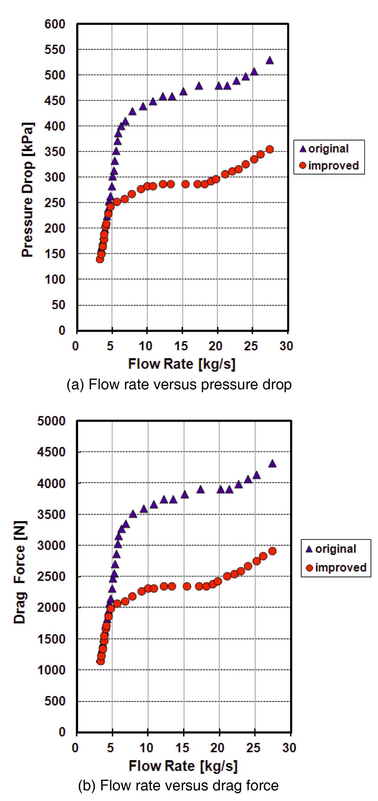
Figure 8 shows the test results comparing the original and improved FARE tool pressure drops at different initial flow rates. The horizontal axis in each figure refers to the initial flow rate (kg/s) of the fuel channel, and the vertical axis refers to the pressure drop (ΔP, kPa) and drag force (N) caused by the FARE tool. The figures show both that the pressure drop and drag force of the improved FARE tool decreased compared to those of the original FARE tool (in the range of 10.0 to 25 kg/s; improved/original = 63%). The reduced pressure drop and drag force resulted in an increased flow rate in the fuel channel.
The drag forces of the improved tool are about 2300 and 2800 N at flow rates of 10.0 and 25 kg/s, respectively.
As the required fluid force for refueling is 1644 N, the drag force of the improved FARE tool provides a sufficient fluid force for refueling.
Figure 9 shows the flow rate changes of the original and improved FARE tool corresponding to the location of the FARE tool during refueling. The figure shows an overall increase of channel flow rate for the improved FARE tool compared to the original tool. The increase of channel flow rate helps to suppress the increase of coolant temperature during refueling, thereby improving the safety and operation of the plant.
4.3 Analysis of FARE Channel Internal Flow
We analyzed the change in flow rate when the FARE tool is used inside the fuel channel. As the fuel channel tubes are connected in parallel between the inlet header and the outlet header of the fuel channel tube, the pressure drop occurring at each channel is equal when evaluated at the inlet header and the outlet header regardless of the FARE tool insertion [3]-[5]. The relationship between the pressure drop and flow rate in each channel can be expressed as
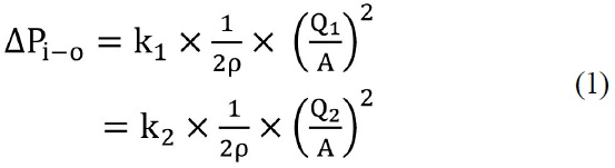
Where ΔPi?o is the pressure drop from inlet header to outlet header; k1, k2 are the pressure loss coefficients in arbitrary channels 1 and 2, respectively; Q1, Q2 are the flow rates (kg/s) in channels 1 and 2, respectively; A(m2) is the crosssectional area of the channel; and ρ(kg/m3) is the fluid density.
From Eq. (1), the equation
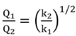
can be obtained
to show the relationship between the flow rates and pressure loss coefficients. This means that the change in the channel flow rate is proportional to the square root of the reciprocal of the change in channel pressure drop.
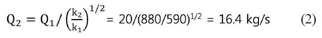
Figure 10 shows the plant on-site measurement results of the channel pressure drop caused by fuel bundles and the original FARE tool. According to this figure, when 12 fuel bundles are loaded into the fuel channel with an initial flow rate of 20.0 kg/s, the pressure drop is 590 kPa. However, when ten fuel bundles and the original FARE tool are loaded in the same channel, the pressure drop is 880 kPa. The channel flow rate change due to the insertion of the original FARE tool is calculated as follows:
For the improved FARE tool, the pressure drop is 170 kPa less than the original FARE tool, as seen in Fig. 8(a). Although this is the value obtained in the laboratory test under the condition of a ten fuel bundles unload, the pressure drop difference can be used to estimate the improved FARE tool flow rate change when used in a real plant with ten fuel bundles load. The flow rate change due to the improved FARE tool is calculated as follows:
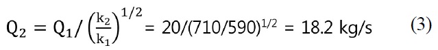
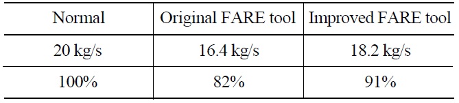
Table 1 show the calculated results, and compares the original and improved FARE tool in terms of the channel internal flow rate when used at a plant site with ten fuel bundles loaded. When the original FARE tool is used in the normally operating channel with a flow rate of 20 kg/s, the channel flow rate is reduced by 3.6 kg/s (18%), from 20 to 16.4 kg/s. In contrast, when the improved
FARE tool is used, the channel flow rate is reduced by 1.9 kg/s (9%), from 20 to 18.2 kg/s. When the improved FARE tool is used, the channel flow reduction is about 50% of the original FARE tool.
4.4 Plant On-site Test at Wolsong NPP Unit 2
After confirming through laboratory testing and analysis that the improved FARE tool performance is sufficient for application to a real plant site, an on-site refueling test was conducted at Wolsong Nuclear Power Plant Unit 2. The on-site test was carried out in two stages during August 12-22, 2009.
In the first stage, a latching/separation test between the improved FARE tool and the plant site refueling supporting equipment rams was conducted. No problems occurred during ten rounds of latching/separation tests between the FARE tool and the rams. In the second stage, a real refueling test was conducted with the improved FARE tool on August 22, 2009 at 60% of full power. The target refueling channel was the B-14 channel shown in Figure 1.
Figure 11 shows the channel flow rate change during the whole process of refueling when the original and improved FARE tools were used. The original FARE tool caused about 4 minutes of low flow rate below 80% of normal flow during the whole process of refueling. A flow rate below 80% of normal flow causes a low flow rate alarm signal in the plant operation. However the improved FARE tool completely eliminated the low flow rate alarm
[Table 1.] Flow Rate of the FARE Channel

Flow Rate of the FARE Channel
signal by maintaining the flow rate above 80% of normal flow during the whole process of refueling. The improved FARE tool kept at least a 5% margin from the low flow limit, and refueling work with the improved FARE tool was successfully completed without any problems.
CANDU-type nuclear power plants use a flow-assist ram extension (FARE) tool as a refueling aid for the refueling of fuel channels. The existing FARE tool showed an inadequate flow rate in the fuel channel for a period of time during the refueling process.
We identified the cause of the low flow rate phenomenon associated with the existing FARE tool. The excessive low flow phenomenon in the FARE channel was attributed to the delayed opening of the orifice ring inside the channel and to excessive pressure loss occurring when the FARE tool passes the linear tube hole.
Based on this understanding, a new FARE tool design that would solve the low flow rate problem was developed and built. This new design was tested many times using a refueling test apparatus in order to determine the optimum design parameters. For a performance test at a real plant under conditions of high temperature and high pressure, tests were carried out at Stern Laboratories, Inc. in Canada. Finally, a plant on-site test was performed at Wolsong Nuclear Power Plant Unit 2 in Korea. This refueling test with the improved FARE tool was successfully completed without any problems. The low flow rate phenomenon (below 80% of normal flow) was eliminated with the improved FARE tool. Several additional improved FARE tools were manufactured and are currently being used for Korean CANDU plants refueling work.