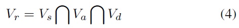
An autonomous unmanned underwater vehicle (AUV) is a marine robot that moves under water in order to collect helpful information about different conditions at the bottom of the ocean, the structure of the upper sediment layer, or the presence of objects and obstacles. Intellectualization of AUV’s control system is critical in order for it to fulfill its mission even in unforeseeable circumstances. The robot must have the ability to control its motion by learning and making logical conclusions [1,2]. The main challenge being experienced by all existing mobile devices that move independently without any control by humans remains that of navigation. Bukhari et al. [3] did considerable work on this problem using fuzzy logic to try to solve the issue of multiple vessel navigation.
For successful sailing in open space, the onboard robot system should be able to build the route, control the motion parameters, and keep track of its own position in real-time mode. One of the approaches to this issue is the integration of the novel algorithm called the dynamic window approach (DWA) to control the motion of the vehicle. Fox et al. [4] were the first to propose the approach in 1997. That proposal led to the changing of automatic control notion in non-permanent environments and enabled the vehicle to move at high speeds. Thus, a dynamic window can be specified as the area of obstacle detection, which depends on the speed of the vessel and can be changed dynamically. The values of several variables of motion must be evaluated after each limited time interval. This process makes it possible for a robot to switch from one to another appropriate velocities and courses while moving at a high speed.
Like all nautical algorithms, DWA chooses and constructs the most appropriate trajectories from initial to destination positions. The major difference from other approaches is that it controls the speed of a vehicle in order to avoid obstacles. For instance, when its sensors detect an obstacle, the robot will decrease its velocity or even stop. Additionally the algorithm allows the AUV to go on at maximal speed if there are no blockages in its path. It is obvious that all the calculations and decision-making processes must be handled dynamically [5].
However, to the best of our knowledge, no research work has been done toward the integration of DWA into autonomous unmanned vehicle navigation systems. We have attempted just such an integration, which we call 3-dimensional (3D) Global DWA. 3D Global DWA enhances DWA with the ability to move in narrow 3D ocean environments.
The remainder of this paper is organized as follows: In Section 2, we discuss the basic ideas underlying a number of previous works related to the topic. In Section 3, we provide the details of our proposed approach. In Section 4, we discuss the results of experiments conducted. Finally, we conclude this paper in Section 5.
A number of methods and approaches applicable to robotics and designed for surroundings rarely change have been presented by researchers [6,7]. However, the types of algorithms used in these approaches are not able to manage and make decisions when faced with dynamic circumstances.
DWA changed the notion of automatic control of objects in unstable conditions, while providing the ability to move robots at high speeds [4]. A dynamic window is the area of obstacle detection that is changing dynamically depending on the speed of the vessel [8].
Initially the technology was applied only to robots that were to be used as serving staff inside an office [4,9]. Another practical example of its application is shown in [10], where the robot with integrated system was tested during exploration in a museum in order to conduct various excursions for visitors.
The number of scientists interested in this method has increased over several decades. This fact is the evidence of its effectiveness. Among these researchers are Brock and Khatib [8], whose work differs from Fox and many others in that they applied the DWA algorithm to holonomic robots, whereas Fox initially applied this method to synchro-drive robots [9]. In addition, the search space in Fox’s approach had a square shape while in Brock’s approach it was a circle.
Researchers started to improve the DWA’s equations after noticing that the robot was likely to go far away from its goal and to increase its speed in some cases while maximizing the objective function. This is why the approach in [11] is stated as being more efficient than the original DWA. In [11], the robot utilizing the proposed motion planning is able to decrease its speed before changing direction on detecting an obstacle.
Seder and Petrovic [12] highlighted the differences between global and local path planning and proposed the idea of combining these two methods into one algorithm for more safe motion that is free of collisions. Their research was based on their previous work [13] but it improved on it by introducing changes that gave robots the ability to avoid collisions even with dynamically moving objects.
Another attempt to improve the global DWA was made by Schroter et al. [14], who tried to use clothoid curves instead of circle to make the process of motion planning more real and closer to machine moving simulation. Their proposed approach was compared with vector field histogram. The virtual force field algorithm has since been modified and expanded to modified virtual force field (MVFF) by Kwon et al. [15]. They incorporated fuzzy logic in order to provide safe tracking without collisions. Their approach is very similar to the one proposed in this article in terms of the way in which obstacles are detected: both our approaches use a circle (in 3D) as a space to control, monitor, and detect any obstacles around the vessel on a distance equal to the radius of the circle far from it.
To describe the proposed algorithm improvements, general information of the marine world and navigation systems must first be provided. An AUV is a marine robot, an automatic self-propelled vehicle with research equipment, which moves under water in order to collect information about the topography of the bottom or the presence of any objects. Usually, the ocean environment is narrow and full of objects travelling independently. One of the works done toward solving the problem of multiple vessels navigating using fuzzy logic was shown in [11]. In that research, vehicles were guided in ocean space by calculating time to closest point of approach (TCPA) and distance to closest point of spproach (DCPA) and bearing values in order to prevent any collisions and provide safe motion from start to target destinations. One of the techniques successfully used in navigation is the Bandler and Kohout’s fuzzy relational products (BK-products) [16]. One of the attempts related to this was done by Anwary et al. [2], who integrated ARTMAP and the fuzzy BK-product method into the onboard system of an AUV and demonstrated its effectiveness by developing a camera based motion system [17].
The limitations of the autonomous planning methods has led researchers to study real-time planning, which is based on the knowledge gained from probing the local surroundings to handle unknown obstacles as far as the robot traverses a path in this environment [18-21]. Similar characteristics are possessed by the approach described in this section based on DWA. We discuss the original DWA in this section and describe the novel navigation algorithm called 3D Global DWA in the ensuing section.
As mentioned before, Fox et al. [4] were the first to propose DWA in 1997. The original purpose of DWA was to handle collision avoidance in robots travelling at high speeds in hazardous and populated environments. Its original idea was to face the problem of the robot’s dynamics by considering only the speed of a vehicle.
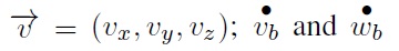
DWA works out with the limitations of velocities and accelerations and provides command generation in a small period of time. This approach is based on a two-dimensional search space using two types of velocities. The pair of values (
Admissible velocities, indicated as
where (
are accelerations for breakage; and
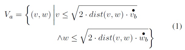
When searching for the set of admissible velocities, the objective function must be taken into account by maximizing its value, as shown in (2) below:
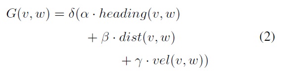
where
The overall search space (
where
are values of translational and rotational velocity accelerations.
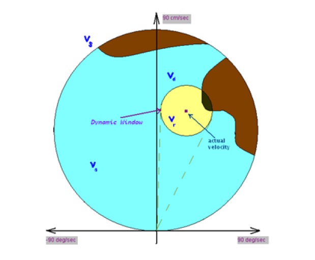
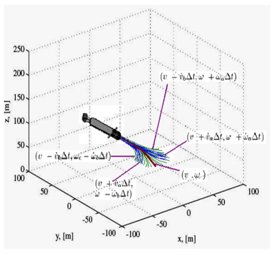
As shown in Figure 1, the space of velocities
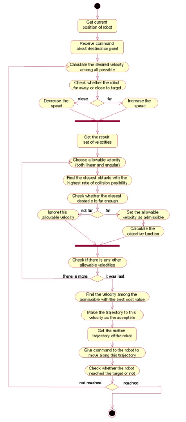
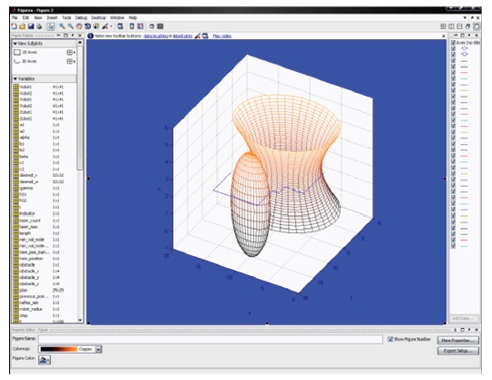
We constructed a unified modeling language (UML) diagram to demonstrate the logic of DWA (Figure 2). First, the acceptable velocity of the vessel to reach the goal must be evaluated taking into account the actual position. Second, the algorithm calculates the allowable linear and angular velocities based on the vehicles dynamics. The following process must be repeated in a loop for the list of allowable velocities: measure the nearest obstacle while the robot travels at a suggested velocity; check whether the values of the braking distance and the distance to the nearest obstacle are equal. The speed must be determined as admissible or nonadmissible. The next step is to measure the objective function, which consists of heading and clearance values. The final step is to determine the cost value for the suggested admissible velocity and to compare it with all the other costs. If the result obtained is the best cost, then the velocity must be considered as the best. Consequently, this velocity will be set to the robots acceptable trajectory.
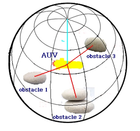
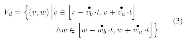
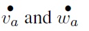
In the previous section, we described DWA’s underlying principles. The next step toward the novel navigation approach is the development of motion control in a 6DOF system. In order to implement this idea, the 3D configuration space (CSPACE) was confined to a 3D dynamic window. This window must be enlarged to the shape of a sphere with radius
With regard to the global coordinate system, the robot’s current position at time
The following formulas present the motion equation for three axes (5):
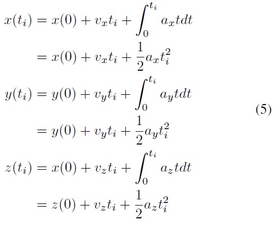
One conclusion can be done based on the formulas above. To achieve a specific command of the speed changing when accelerating at a constant velocity, the vehicle moves along a quadratic curve. It continues along until the desired speed approved by the algorithm is not achieved by the AUV [8,22]. Although the cardioids of these spherical curves depend on the magnitude of the acceleration, acceleration and curvature are mutually proportional. For instance, a small acceleration creates a small curvature of the trajectory and allows the simulation of behavior that is similar to cars [4].
The dynamic window is presented as the set of velocities
If the vehicle can decrease its speed or even stop before collision with obstacles while following the path along the chosen trajectory, then the velocity pair (
Another indicator related to trajectory is known as the path
alignment measure
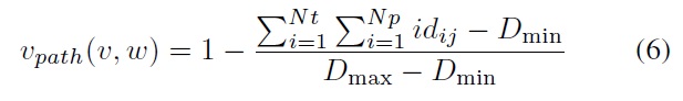
where
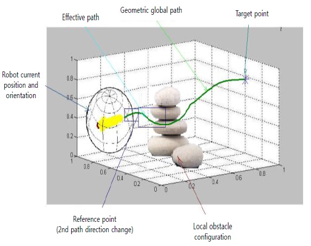
The effective path is a line consisting of a number of points. It binds two states on the path: actual position of the vehicle and a way-mark on the route, as shown in Figure 5.
3.3 Combination of Avoidance Algorithms: 3D Global DynamicWindow Approach
Nowadays, the effective navigation method is usually presented as a system of algorithms genetically related to each other by combining both the autonomous monitoring mode and the realtime path navigation mode (DWA) with a simple map and efficient planning algorithm. The first part of the sailing approach, called autonomous planner, is looking for the best global path from the start to the target, whereas the second part is handling any possible crashes with previously unknown objects. This process is done by replacing a part of the planned global-optimal path with the auxiliary path [23].
The proposed algorithm is an evolutionary navigator that combines autonomous and real-time planning modes with a simple highly accurate map and an efficient planning approach. The algorithm first reads the map and receives the initial and target coordinates.
The Global DWA has already been proposed by Brock and Khatib in [3]. In its essence, DWA has no knowledge about the linkages of points on a path in free space. This is the reason why, in cooperation with a motion-planning algorithm, DWA can overcome this weakness. This function finds the motion that is free of collisions from the initial position to the target point. Our proposed 3D Global DWA (3D GDWA) is based on this concept and underlying idea.
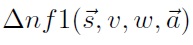
The best-matched motion algorithm has been proved to be the neuro-fibromatosis type-1 (NF1) because of its global, local minima free features [8]. The GDWA path planner is based on the NF1 navigation approach. GDWA integrates the sensor data into an occupancy grid where the robot is presented in the form of a dot. It simplifies the route planning process in a way that the robot will detect the free cell and classify it as the obstacle-free area. The best way from the start to the goal position is denoted as the shortest path that can be found by the NF1 algorithm [24].
While the GDWA is an extension of the original DWA, it is obvious that it uses the same logic and equations as its predecessor. The key difference among them is the objective function (2), which evaluates the possibility of selecting among the potential moves that the robot can make. The novel objective function (7) presented above is changed by adding
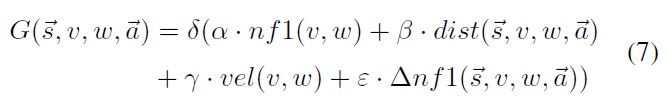
To determine
shows the extent to which the motion command will decrease the space between the vehicle’s current position and the target point during the next repetitions.
In previous sections of this paper (Section 2 and Section 3.1), a number of approaches were described. According to the information collected, our proposed 3D GDWA is considered to be one of the best methods for navigation systems for AUVs in narrow marine environments. The reason is that it complies with the requirements for any navigation algorithm described subsequently.
The main purpose of motion planning and path following approaches is to avoid collisions, not to stop the vehicle if there are still possible ways to go, and finally allow the robot to go as fast as possible. An algorithm is called an obstacle avoidance algorithm if it prevents the robot from colliding during its traversal of the entire path, which increases the importance of the accuracy and speed of searching new obstacles. Obviously, the map must be precise. There are several factors that can affect the velocity of the vehicle, but the narrowness of the surroundings should not force the algorithm to reduce the speed to any large extent.
It is a well-known fact that the histogram grid is a quick and secure mapping technique for tracing dynamically moving obstacles. In addition, it helps in collision avoidance by dividing velocities into admissible and non-admissible groups (DWA). The vehicle can be pulled away from the problem of getting stuck by using the histogram grid because another non-blocked way of travelling can be found.
In conformity with the information provided in this paper, 3D GWA has been demonstrated as an approach that has the capacity to securely navigate obstacle courses while moving at a high speed.
In summary, in the first part of the proposed algorithm, (autonomous planner), the robot looks for a globally optimal path from the start to the target, while in the second part, the 3D GDWA algorithm is responsible for processing potential collisions or previously unknown objects, replacing part of the original global path to a sub-optimal path. Finally, in experiments conducted, both in the articles referenced above and in
this research paper, it is proven that the robot with the integrated approach has the ability to navigate obstacle courses traveling as fast as the platform allows. On the basis of these conclusions, we chose the 3D GDWA as the algorithm to implement and further test.
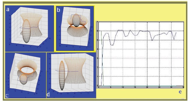
To evaluate the reliability of the proposed method, we conducted experiments in which we used MATLAB (Mathworks, Natick, MA, USA) to handle all the calculations and draw the images of the resulting paths, as shown in Figures 6 and 7.
The results of the experiments conducted illustrate that the algorithm is supremely managed all the assigned navigation tasks. More specifically, it built the most optimal path from the start to the target points; herewith, it did not expose the AUV to any risk of colliding with any of numerous obstacles (Figures 6,7a?d). These obstacles were presented in the form of spheres and cylinders. As can be seen in the image, the robot avoided the obstacles and successfully reached the target without any crashes.
Furthermore, 3D GDWA provides additional features for controlling the dynamically changing speed values. As shown in Figure 7e, the speed of the AUV varied (rising and decreasing) depending on the route, presence of obstacles, and remoteness from the goal point.
The above arguments point to the effectiveness of the proposed algorithm while using it in the narrow surroundings of the underwater world, which in turn can be used for any type of AUVs.
We also set motion planning values for the vehicle that was used in the simulator (Table 1). They were generated based on
[Table 1.] Technical prerequisites for motion planning
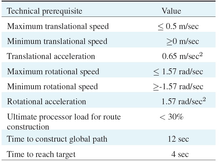
Technical prerequisites for motion planning
the basic requirements for a vehicle that is able to perform tasks related to AUVs.
In the various attempts to create an autonomous moving vehicle or mobile agent, a number of issues have appeared, organized under the title “navigation tasks.” This is not only about movement on the Earth’s surface but also about the movement of vehicles or guided missiles.
Global planning algorithms incorporate information about the whole space in order to identify areas where it is possible to move, and then determine the best path. The planning heuristic methods reduce the complexity of the task and the sensitivity to errors in the data in various ways. Thus, for the development of a universal autonomous robot path following system, a navigation evolutionary algorithm was selected.
The Global DWA was developed for 3D marine environments and proved to be an effective solution to navigate AUVs in underwater surroundings.
Selection of this algorithm makes it possible to take into account a set of behaviors of a vehicle and the environmental aspects in the path planning stage. However, one key challenge in the proposed method still remains: namely, inability of the vehicle to go up or down when avoiding obstacles. Another aspect to take into consideration is the factor of dynamic obstacles because they were not simulated in the current study. Additionally, it must be supposed that the vehicle does not know the exact trajectory of these kinds of obstacles. The solution to these problems will form the basis of future research.