Given their ability to walk, leg-based mobile manipulation systems are very convenient to work with in normal as well as in irregular environments [1-3]. For achieving the desired mobility, it is important to design a multiple-leg mechanism and manage system balance in a manner wherein there is adequate coordination among the legs. For instance, if any of the legs in a quadruped walking configuration is incompatible with the others, the robot may not remain in equilibrium. Therefore, proper coordination among the legs is required for achieving system balance and the desired walking performance in the stationary state as well as while maneuvering. A performance measure is helpful for identifying system balance during robot walking. From a geometric viewpoint, a few criteria have been put forth for ensuring stable quadruped walking [4-7]. In addition, an energy-based stability margin has been considered for the potential stability of legged walking robots [8,9]. Recently, Bretl and Lall [10] attempted to evaluate the static equilibrium by considering the foot placement. However, the body’s falling direction may not have been considered in the aforementioned approaches. In contrast, when a robot is off balance, suitable foot stepping or walking steps can be executed for restoring the system balance. Additionally, for taking a step, the robot needs to know the location of the foot to be moved. In fact, the next foot location for effective balance compensation could be determined by testing an effective measure. However, comprehensive studies on identifying and compensating for the balance of quadruped walking systems are rare.
The objective of this study is to analyze the balance of quadruped walking configurations using a boundary-range-based balance margin. In addition, suitable compensation for system balance through foot stepping is addressed.
2. QuadrupedWalking Configuration Model
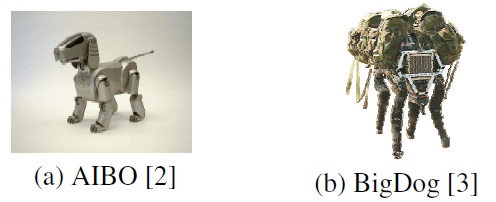
Consider a representative quadruped robot system such as a dog, shown in Figure 1a. The AIBO robot is a well-known example of four-legged mobile manipulation systems. Thus, many researchers have been interested in the locomotion of the robot that can be used as a test bed for walking algorithms. The four-legged robot shown in Figure 1b is well known and is actually used for delivery and exploration tasks in rough terrain. A stable walking strategy is usually required for quadruped tasks, and the walking mechanism’s stability is closely related to the shape of the polygon formed by its supporting feet. That is, system balance is influenced by the placement of the mechanism’s feet. If the walking configuration is well balanced, the given task is executed with ease.
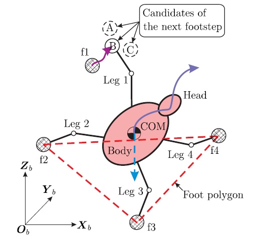
For dealing with such a quadruped walking problem, we consider a simple model of a four-legged robot, shown in Figure 2, where
So long as the vertical projection of a multi-legged robot’s center of mass (COM) lies inside the supporting foot polygon [1], it can walk stably. During walking, the foot polygon varies based on the location (A, B, or C for f1) of the moving foot, as shown in Figure 2. If the location of the first foot (f1) is assigned as A, the system balance improves intuitively. Therefore, our goal is to devise a feasible measure for identifying the degree of balance of any quadruped walking configuration and demonstrate the applicability of said measure to the analysis of quadruped robotic walking.
3. Boundary-Range-Based Balance Margin
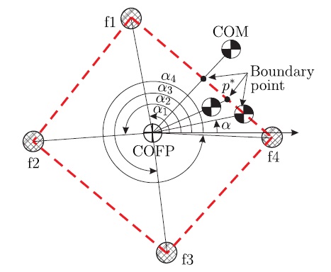
Consider an arbitrary motion of a quadruped robot in a landing situation, as shown in Figure 3. The landing situation implies that all feet are stably on ground, and the entire range of body motion within the operating range of the robot system is available. For effective description, we approximated body motion to the movement of the robot system’s COM.
In general, a quadruped robot system can attain a balanced posture so long as the vertical projection of its COM lies within the boundary of its foot polygon. The balance worsens if the vertical projection of the robot system’s COM lies outside the foot polygon. Based on this concept, we propose a boundaryrange- based balance margin that can be used for checking the degree of balance of a quadruped walking configuration. Figure 3 shows a schematic diagram of the process of defining the boundary range based on a quadruped robot’s motion. Here, each foot lands on the
In order to present the balance margin during walking, we first check the point of intersection of
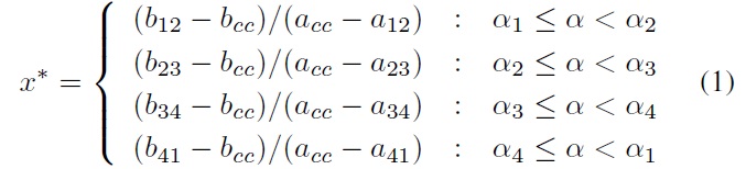

where
Second, if the

where
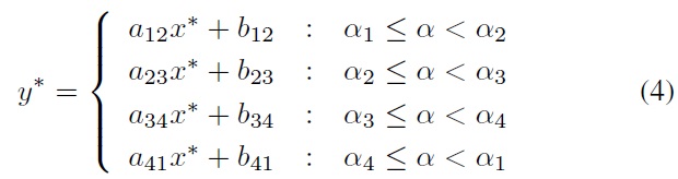
Third, if the

where
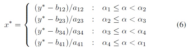
Finally, if all positions of the COM and the COFP are identical, the intersection point is determined to be on the boundary of the foot polygon such that the distance between the COFP and the edge of the polygon is at its minimum.
Following the above-mentioned procedure, the


Given that the boundary ranges include the directional information of walking motion, they are useful for analyzing the directional balance of the quadruped robot in the stationary and walking situations.
We finally define the


where the values of
4. Simulation for Balance Analysis
This section shows exemplary simulation results to analyze the balance of the quadruped robot system doing some stationary motions or walking.
4.1 Balance Trend as Stationary Motions
The effort to identify the system’s balance is basically important to achieve the performance of a walking robot system performing a stationary motion or a mobile manipulation. So, the goal of the first simulation is to analyze the stationary balance of the robot system by estimating the boundary range and the balance margin described in Section 3. through some exemplary motions.
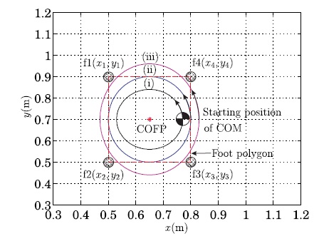
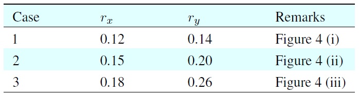
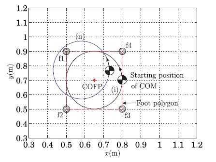
The three trajectories shown in Figure 4 have been considered for the first simulation. These trajectories imply the body motions for some manipulation tasks of the quadruped robot and they specified as the trajectories of the COM projected on the planar ground space. Those COM trajectories are represented by


where
[Table 1.] Parameters of rx and ry for the case studies

Parameters of rx and ry for the case studies
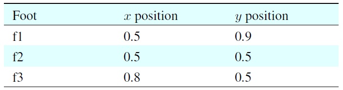
[Table 2.] Positions of four feet standing on planar ground

Positions of four feet standing on planar ground
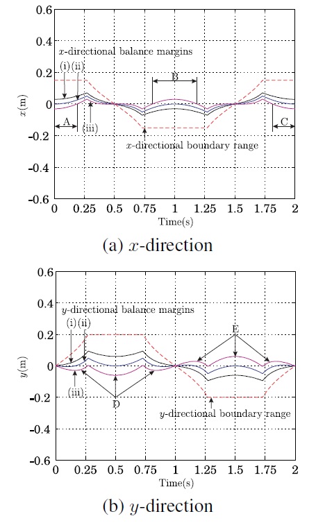
In particular, the first case in Figure 4 implies that the stationary motion of the robot’s body is performed in the inside of the foot polygon and its pattern is an elliptical shape. The second case shows that the motion approaches to the boundary of the foot polygon. The third case shows that some parts of the motion are performed in the outside of the foot polygon. The current positions of the four feet have been specified in Table 2. In this situation, the
Figure 5 shows the
4.2 Balance Compensation by Foot Stepping
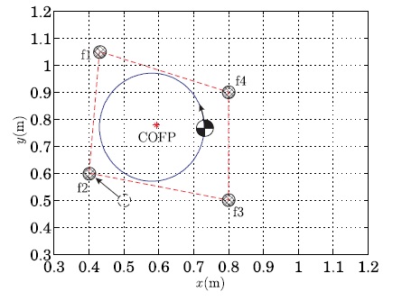
In order to consider the issue of balance compensation by foot stepping, we especially used the two trajectories shown in Figure 6. Actually, the second trajectory is to consider a moving situation for a walk so that some parts of the body’s motion are out of the stable range of the foot polygon and the walking system is to be unbalanced.
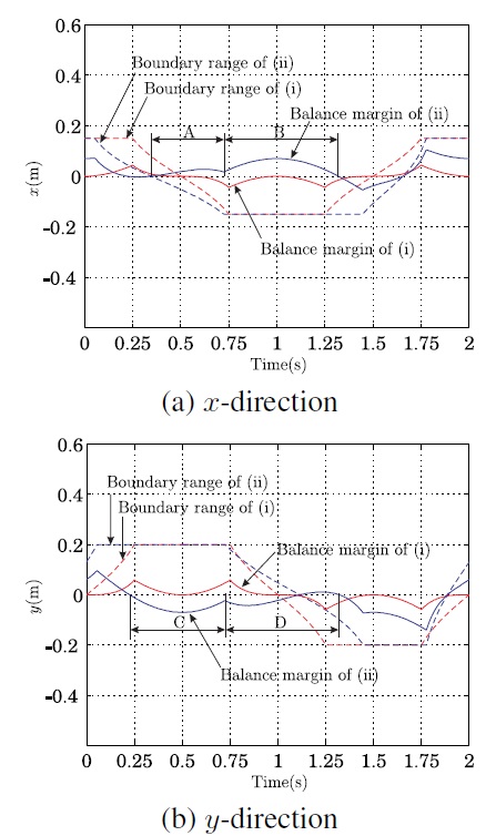
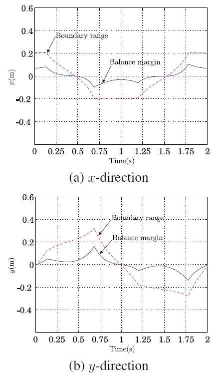
Figure 7 shows the boundary ranges and margins for the given motions in Figure 6. It is found that the quadruped robot has some margin for the stability in the motion of the first case. However, the balance margins at the regions of A-D in Figure 7 are inadequate to achieve the second motion stably without walking.
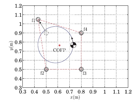
Now, we tried to move a foot in order to compensate the unbalance. Figure 8 shows that the first foot has been moved for the balance compensation during the second motion. The objective of this simulation is to show the improvement of the system balance when the first foot f1 is moving to a suitable position of
In order to compensate such an unbalance, the robot can try an additional foot stepping by the second foot f2 as shown in Figure 9. Figure 10 shows the resultant boundary ranges and balance margins by the second foot stepping. Finally, we can confirm that the system balance has been made stably. Therefore, our analysis of balance compensation through appropriate foot stepping can be applied for effective gait generation of quadruped robots.
The main conclusion of this study is that the balance of quadruped walking robots can be identified using the proposed boundaryrange- based balance margin. Through exemplary simulations using certain standing and foot-stepping motions, we demonstrated the effectiveness of the proposed measure. Additionally, the effect of balance compensation through appropriate foot stepping was analyzed. We finally concluded that the boundaryrange- based balance margin can be applied to determine the foot to be moved and its optimum landing location for effective balance restoration, and that the measure can contribute to improving the system balance over the course of a reasonably long walk. In addition, the proposed measure can be applied to the development of a footstep-planning strategy for ensuring effective quadruped walking.