Driver-assistance technologies are the subjects of widespread research and development in the car industry, especially computer-vision-based driver assistance [1]. Computer-vision-based driver monitoring is aimed mainly at detecting sleepiness and distraction using a camera mounted in front of the driver (e.g., on the dashboard). By studying and analyzing the frames recorded by the camera, the system can provide feedback or warn the driver if their state is abnormal, even in non-ideal lighting conditions [2]. Research is focused on detecting the signs of sleepiness, particularly by analyzing a driver’s eyes and their gaze. For example, long blinks shows that a driver is experiencing fatigue. Gaze detection can also determine where a driver is looking. When the eyes focus in one direction for a long period, this indicates that driver may be experiencing distraction.
However, some situations must include head pose estimation, e.g., eye detection will not work if a driver is wearing (dark) sunglasses while driving, and eyes cannot be detected on occasions when the driver is wearing a hat. The direction of the head can convey important information, so we can use head poses to understand where driver is focused and to determine a driver’s state while driving. For example, a sudden head movement while driving may indicate that the driver is looking at something special outside the car. Long-term bowing or frequent nodding can also indicate that the driver is tired or sleepy. In these cases, it is better to use head pose analysis to determine whether a driver is distracted or suffering from sleepiness. These issues are addressed in this paper. Our goal is to develop a system that can provide a robust estimation of a driver’s head pose to analyze the status of the driver. This is achieved by
The remainder of this paper is divided into the following sections. Section 2 provides a brief description of previous headpose estimation approaches. Section 3 describes the details of our proposed system. Section 4 presents all the experiments we conducted, with a discussion of the results. Section 5 provides our conclusions and possible future work.
Previous head-pose estimation approaches can be grouped into
The proposed head-pose estimation system is able to provide the roll, yaw and tilt angle of the driver’s head from a monocular image sequence. Then, according to those angles and detected changes of them, we will be able to understand the status of the driver.
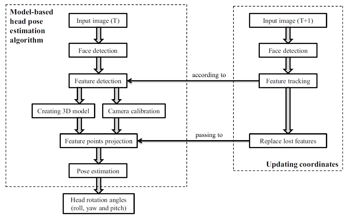
The flowchart in Figure 1 demonstrates basic procedures of the proposed head-pose estimation system. A monocular image is the input of the system for one run. Initially, face detection is applied to find the face region in the input image. The detected region is considered to be the
Then, the system detects the
In the proposed system, because POSIT and PnP are utilized for pose estimation, both require not only the feature points in 2D coordinates on the image plane but also corresponding 3D coordinates which are located on the surface of the 3D model. Therefore, the projection points of the 2D feature points on the 3D model have to be computed beforehand.
Moreover, by camera calibration we calculate the focal length of the used camera before computing 3D projection points and implementing the POSIT pose-estimation function, and also the camera intrinsic matrix and distortion coefficients needed for implementing the PnP pose-estimation function.
Finally, the pose-estimation algorithms are used to calculate or update the affine transform of the driver’s head. Based on the rotation matrix, the system computes roll, yaw, and tilt angles of the driver’s head. Then, the created 3D model is rotated based on those three estimated rotation angles (e.g., for visualizing the head pose). As a consequence, the viewing direction of the driver can be detected.
Moreover, to analyze the status of the driver, the system has to work on a sequence of images to study changes in roll, yaw and tilt angles. Thus, a procedure for updating the coordinates is also included. It consists of detecting the new face region in the new input image and tracking previously detected good features. Then, as some of the good feature points are lost during tracking, the number of lost features is replaced by newly selected ones. Next the updated good features will be passed on to the process of feature point backprojection. At the end, the new pose is estimated according to the updated feature points.
After applying all these processes on a sequence of images, we analyze the results for providing information about the status of the driver. The remaining parts of this section describe the procedures more in detail.
The camera is assumed to be mounted on the dashboard in front of the driver. Face detection is the first step for locating the head. For initialization, we assume a frontal view on a face where yaw, tilt, and roll angles are small. In general, a driver is looking forward, thus we can expect that this initialization state occurs in a reasonable time.
The most descriptive head feature points are in the face region. Compared to this, using a profile face view or other angular face views for initialization works against robust and “meaningful” feature detection, and creates an uncertainty for the initialization of head pose angles. The Viola-Jones face detection approach is used for detecting the face region by simply using the pretrained frontal-view cascade classifier from the OpenCV library due to its robustness and high performance for the considered initialization step.
Tracking the movement of individual feature points in the face region provided for us better results (for understanding head rotation) than tracking the whole face region at once. We apply the KLT feature detector for selecting the features in the face region. Detected features are evaluated for their quality (their trackability), thus defining selected good features within the detected face region. These features are stored in descending order according to their
There are many different 3D models that can be utilized for representing a driver’s head. Popular 3D models are the cylindrical head model, the ellipsoidal head model, a detailed active appearance model, or a planar model. For the detailed active appearance model, there are many degrees of freedom that need to be considered when initializing the model. Furthermore, its tracking performance is not regarded as being robust and precise [16]. The cylindrical or ellipsoidal head model appear to be more preferable due to simplicity (fewer degrees of freedom, reasonable fits to a human head).
According to experimental results in [16], the 3D cylindrical head model can provide robust performance on yaw and roll, but is unstable for tilt. Therefore, for the proposed system, we decide to render an
As mentioned before, camera calibration is needed due to the requirement of both pose estimation algorithms, as well as the approach which is used to backproject 2D points onto the 3D ellipsoidal model surface. By calibrating the camera, we only need to obtain the
3.6 Backprojection of 2D Points
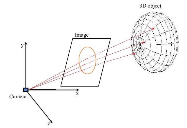
In order to get rotation angles to render the ellipsoid model at the correct pose of the driver’s head, we compare the performance of PnP and POSIT pose-estimation methods. We have to provide not only coordinates of 2D image points but also their corresponding 3D coordinates on the surface of the ellipsoid. The feature detection stage provided the 2D feature points. In this step, we calculate their corresponding 3D points which are projected back onto the surface of the ellipsoid.
The concept here is to calculate the intersection of rays with an ellipsoid [20]. A ray is defined by
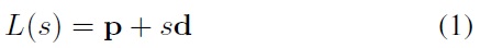
where
Next, a general ellipsoid is represented as below, where

However in our system, we utilize an ellipsoid of revolution with a pair of equal semi-axes (i.e.,

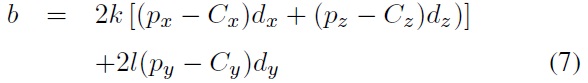
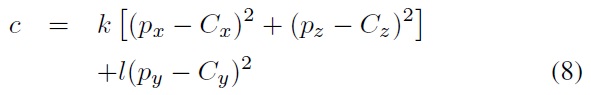
By substituting Eq. (1) into Eq. (3), the intersection is defined by
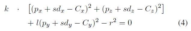
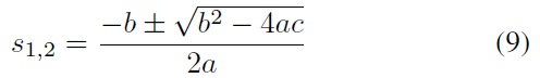
simplified as a quadratic equation in the form
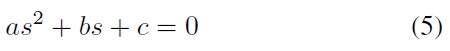
with

[Table 1.] OpenCV pose estimation methods
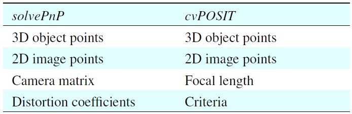
OpenCV pose estimation methods
and solutions
By substituting
Now we have 2D feature points and corresponding 3D coordinates on the ellipsoid surface; we are ready to estimate the pose of the driver’s head.
For this stage, we implemented two different pose estimation methods from the OpenCV library,
In fact, all the previous steps are the preparation stages for triggering these pose estimation methods. Once the program is initialized, the requested 2D points can be obtained from the feature detection step as well as the corresponding 3D points on the surface of the ellipsoid. These data are required by both pose-estimation methods as indicated by Table 1. Data
The previously described steps are all for initializing head pose estimation. In order to analyze the status of the driver, we also analyze subsequent frames for providing a sequence of head-pose estimations.
By using initial 3D model points and updated 2D points, both tested pose-estimation algorithms provide updated estimations. However, two problems need to be solved. First, when a driver’s head is rotating, tracked feature point get lost. As a result, there are insufficient feature points to be fed into the pose estimation algorithms. As a consequence, they will not be able to provide robust estimations for a driver’s head. Second, there is the goal of automatically re-initializing the system. We need to decide when and how to re-initialize, such that time-efficiency and system performance is guaranteed.
In the following sections, we describe how to update 2D coordinates for generating new estimations of the driver’s head pose, as well as how to solve those two problems mentioned above.
Updating of 2D coordinates consists of two steps: tracking of feature points and replacing lost feature points by newly detected ones.
As illustrated in Figure 1, in order to increase the performance of tracking, face detection is applied again for the new input image. However, at this time, face detection is based on frontal and profile face detection, as well as on the previously detected face region. The reason is that the face in the new image may not be the frontal view. If not, the face will be detected by using profile-detection procedure or according to the previously detected face region due to the small displacement between two consecutive frames. Once the face region is again detected or estimated, the KLT tracker will track previously detected features within this region.
However, by experience, many features will be lost due to the preset constraints. Not only due to head motion, there are various other reasons which can lead to tracking errors, such as illumination changes, feature location occlusions, and so on. Thus, in order to prevent bad pose estimation due to a lack of feature points, lost feature points are replaced by using newly detected feature points. Once the replacing process is finished, the feature list is updated. Next, the new 2D and 3D correspondences will be obtained, then new pose estimation will be calculated.
According to our design, the system has to be able to do reinitialization automatically. For example, based on the detected head pose it could be decided when to trigger the function for replacing lost feature points. However, a simple approach of replacing lost features in every
about 0°, 15°, 35°, etc.), and so on.
We take every fifth frame as a re-initialization frame to replace lost features. More in detail, contributing processes perform the following:
1. Estimate the head pose; if a frontal-view face then first (re-)initialization.
2. Calculate three head-rotation angles for the first (re-) initialization frame.
3. Trigger the function to replace lost features.
4. Estimate the head pose in the following frames, until the next re-initialization frame, according to newly updated features.
5. Calculate the head rotation angles for the current frame. The result will be referred to as that for the most recent re-initialization frame.
6. Adding newly calculated head rotation angles which refer to the most recent re-initialization frame for providing the head rotation angles which refer to the frontal view face.
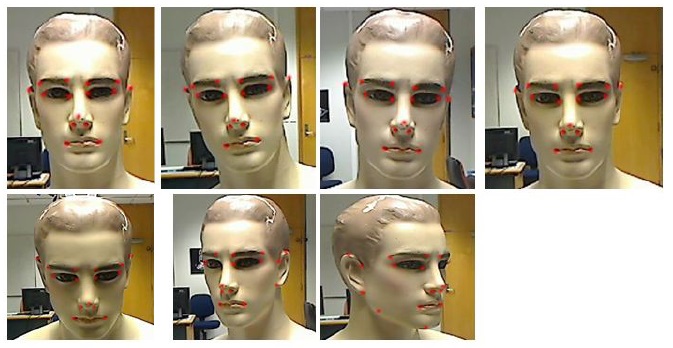
We conducted extensive experiments using our proposed system with image sequences recorded in a test vehicle. However, these real-world data lacked ground-truth data for comparison. Thus, we also developed an approach for generating ground-truth data. We compared the estimated results (using the PnP and POSIT pose-estimation approaches) with the head-pose ground-truth data, which were obtained from manually marked feature points or automatically tracked feature points in the input images.
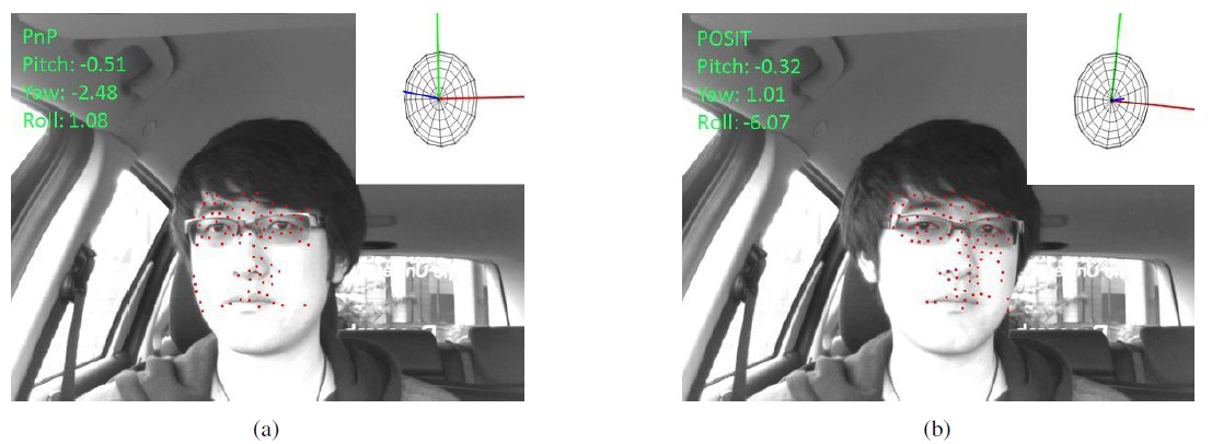
To achieve this, we used a mannequin model as our test object and recorded three sequences: one for changing the tilt angle
only, one for changing the yaw angle only, and one for changing the roll angle only. Sample input images and their manually marked feature points are shown in Figure 4.
4.1 Using Mannequin Model Sequences
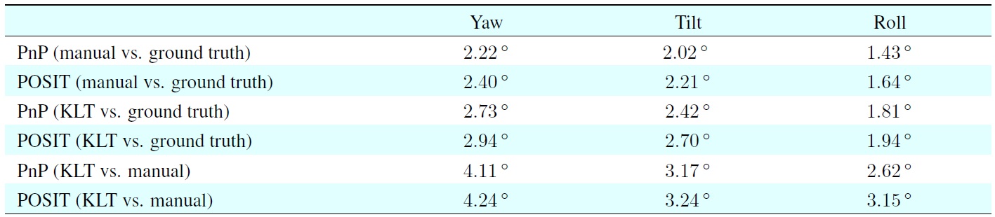
Based on experiments using mannequin model sequences, we were able to determine the accuracy of our results when using manually marked feature points for head pose estimation or the results when running our system to automatically detect feature points, and we compared the results with the ground-truth head pose data. We calculated the standard deviations of the errors between the pose results based on manually marked feature points or the KLT-detected feature points compared with the measured mannequin head pose.
The first four rows in Table 2 show the standard deviations of the errors for the estimated angles, which were obtained using both pose estimation approaches with manually marked feature points or KLT-detected features, compared with the ground-truth data. In general, PnP provided better estimates than POSIT, while the manually marked feature points yielded
[Table 2.] Standard deviations of the errors

Standard deviations of the errors
PnP results
better results than automatically (here: KLT) detected feature points.
The results obtained using manually mark points were very close to the (measured) head-pose ground-truth data. Thus, they can be regarded as
This required fewer replacements of lost feature points, and to more accurate and robust estimates. The estimated yaw angles had the largest standard deviation error. This was because the changes in yaw angle could be very large and a large yaw angle change required more replacements.
As mentioned earlier, both pose estimation approaches were sensitive to changes in the feature points. Therefore, there were bigger errors when estimating the yaw angle. The accuracy of the estimated tilt angle was between the yaw and roll angle estimates.
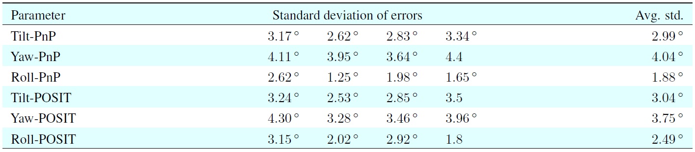
The last two rows in Table 2 show the standard deviation error for the KLT approach relative to the manually marked points approach. These values can be used as reference for checking the accuracy of the results when applying the pose estimation approaches to test vehicle sequences.
4.2 Using Test Vehicle Sequences
We applied manually marked feature points to four test vehicle sequences (including scenes of a non-occluded driver’s face, eyeglasses, and dark sunglasses) to provide a
Table 3 shows that the average errors were very similar to the errors shown in the last two rows in Table 2. This demonstrated that the use of the mannequin model sequences was appropriate. Our system can provide relatively accurate estimates of a driver’s head pose and PnP provided better results than POSIT using our proposed system.
5. Conclusions and Future Work
We developed a model-based monocular head pose estimation system that utilizes a novel form of backprojection and a KLT feature tracker for selecting, tracking, and replacing feature points in a detected face region, as well as calculating their corresponding 3D coordinates on the surface of an ellipsoid model to estimate the pose of a driver’s head and to analyze the status of the driver’s head.
There is no publicly available source code for other headpose estimation methods, so our comparisons were limited to re-implementation. However, we compared two different pose estimation algorithms: PnP and POSIT. Using the results for manually marked feature points as
It would be interesting to test the performance of other feature points (e.g., SIFT and Harris corner detector) to improve the accuracy of our estimation results. Moreover, the rapid advances in mobile devices, such as smartphones, means that a mobile device application would be a very useful extension of our system. We could obtain many advantages from mobile device applications. For example, the majority of smartphones have a built-in camera so we would simply mount it on the driver’s side of the windscreen instead of using a separate camera.
No potential conflict of interest relevant to this article was reported.