검색 전체 메뉴
PDF
맨 위로
OA 학술지
Shaded-Mask Filtering for Extended Depth-of-Field Microscopy
  • 비영리 CC BY-NC
  • 비영리 CC BY-NC
ABSTRACT
Shaded-Mask Filtering for Extended Depth-of-Field Microscopy
KEYWORD
Aberrations , Apertures , Diffraction theory
  • I. INTRODUCTION

    Imaging systems with a high depth-of-field (DOF) are required in many applications across different fields [1-5], such as microscopy [6-8] and communications [9]. However, most imaging systems described in the literature are very sensitive to defocusing. This means that small misalignments between the object and image plane impose great limitations on the imaging systems. In order to increase the DOF of these systems, numerous studies have been carried out recently along these lines [10-16].

    The trivial method for increasing the DOF is to reduce the numerical aperture (NA) of imaging systems. However, this provokes a dramatic decrease in the transverse resolution: there exists a compromise between the transverse resolution and DOF. Thus, considerable effort has been expended in attempting to increase the DOF of imaging systems without undermining their resolution. In a particular case of the extension of the DOF while maintaining the transverse resolution [8,13], many pupil masks have been designed based on phase [6,7,13-15,17,18] and/or amplitude [19-21]. It is of interest that the advantages of phase masks are superior to those of amplitude masks, including the fact that the most recently developed amplitude masks are not sufficiently light efficient. Another technique is the utilization of a multifocal concept, which uses various lenses of different focuses [22].

    In this work, we analyze the enhancement of DOF in imaging systems. For this, we employ the analogy between the axial behavior of a system affected by spherical aberration and the transverse response of an imaging system. To study the increase in the DOF, we implement an amplitude filter in two optical systems. Similarly, any other filter designed to reduce the spherical aberration can be used to increase the DOF.

    The paper is organized as follows. In Section II, we derive the equations that describe an optical system affected by spherical aberration. Also, as a specific case worth analyzing, the complex amplitude distribution is particularized to study the axial behavior of the imaging system. Section III is devoted to demonstrating the similarity between the axial response of an imaging system with spherical aberration and the transverse response of an optical system. Finally, in Section IV, we set up two different experiments. The first of them is implemented in an imaging system whose NA is low. For this case, we show both the numerical and experimental verification; the high agreement between them is clear. The second experiment is performed with conventional scanning microscopy. To sum up, in Section V, we conclude the main achievements of our research.

    II. THE MISMATCH INDEX-INDUCED SPHERICAL ABERRATION

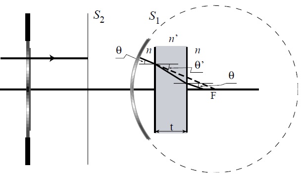
    In this section, we study the aberration in a high-NA system when the wave field is focused through several media stacked perpendicularly to the optical axis.

    Let us start by considering a high-NA objective lens illuminated by a monochromatic collimated beam with wavelength λ. The geometry of the objective is illustrated in Fig. 1. Contrary to what happens in the paraxial approach, the objective is characterized by its principal surfaces, which are a planar surface, S1, and a spherical surface S2, with focus f and centered at the focal point, F. In most of the high-NA objectives reported in the literature, the aperture stop is located at the back-focal plane. Thus, if a monochromatic planar wave strikes the objective lens, the emerging wave field is a truncated spherical wavefront [23]. This wavefront is focused passing through a dielectric layer, the coverslip, whose thickness is t and refractive index n’, immersed into a medium with a different refractive index.

    The amplitude distribution at the neighborhood of the focal plane can be calculated according the scalar, nonparaxial Debye’s formulation [24] and assuming that the sine condition [25,26] holds. After straightforward maths, the complex amplitude distribution along the optical axis is given by [27]

    image

    where w40 and w20 are, respectively, the well-known spherical-aberration coefficient and defocus coefficient, as measured in units of wavelength, and q(ζ) is the apodized amplitude transmittance of the aperture stop.

    III. DESIGN OF BEAM-SHAPING ELEMENTS TO INCREASE THE DEPTH-OF-FIELD

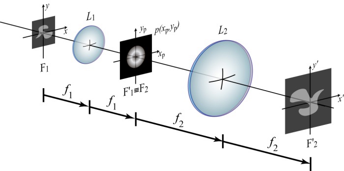
    Our aim here is to study beam-shaping elements that increase the DOF of optical systems. For that, let us consider a conventional two-dimensional (2D) imaging system, which basically consists of a telecentric arrangement, as shown in Fig. 2.

    The telecentricity provides two important properties to the system: the system is 2D linear and shift-invariant. Therefore, the 2D irradiance distribution at the image space can be expressed as the 2D convolution between a scaled version of the 2D object and a 2D function, which is called the intensity point-spread function (PSF) of the imaging system [28],

    image

    where M = ? f2 / f1 is the magnification of the imaging system and the intensity PSF is then obtained as the square modulus of the amplitude PSF

    image

    where, p(xp, yp) represents the amplitude transmittance of the aperture stop (Fig. 2). We have also omitted some irrelevant factors. In the particular case in which the pupil function is separable in Cartesian coordinates, the amplitude PSF can be rewritten as h'(x,y;z) = h'x(x;z)h'y(y;z), being

    image

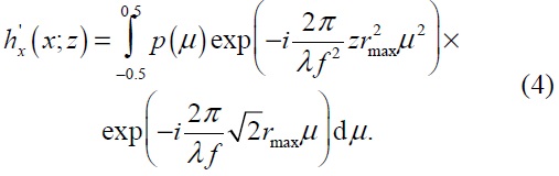
    Note that the coordinates in the aperture stop plane have been normalized as

    image

    where rmax is the radius of the circle in which the square pupil is inscribed.

    It is interesting to note the similarity between Eqs. (1) and (4). This implies that the axial response of an imaging system affected by spherical aberration behaves similarly to the transverse response of an imaging system with a square pupil. This reasoning leads us to conclude that the amplitude profile family designed to reduce the spherical aberration may also be used to provide greater tolerance to defocusing in imaging systems.

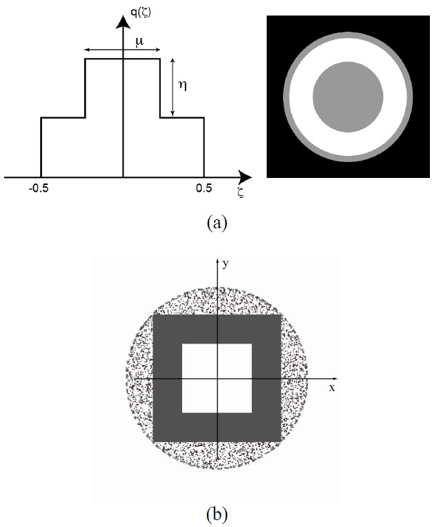
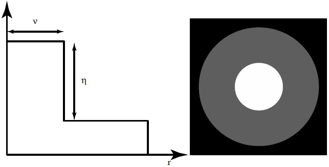
    The general case study can be particularized to the case of binary masks known as shaded ring (SR) filters. These filters are composed of three annular zones with two different transmittances, and each mask is uniquely specified by two construction parameters (μ, η) as defined in Fig. 3. From Fig. 3, it is trivial to realize that a square filter produces a significant loss of resolution in certain transverse directions because the entire pupil size is not used. Consequently, a corresponding radial version has been designed (Fig. 4), where the transverse resolution is now the same in all directions. After a numerical optimization procedure [29], we have selected the values μ = 0.4 and η = 0.7.

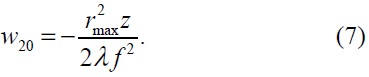
    Obviously, to evaluate the PSF in this case, it is more convenient to rewrite Eq. (12) in cylindrical coordinates. Moreover, by employing the analogy with the axial response of an imaging system with spherical aberration, the amplitude PSF is
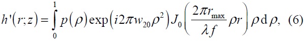
    image

    where ρ = rp / rmax and the defocus coefficient is defined as

    image

    IV. EXPERIMENTAL VERIFICATION

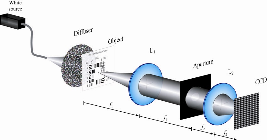
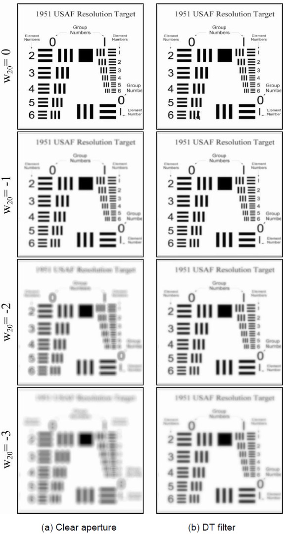
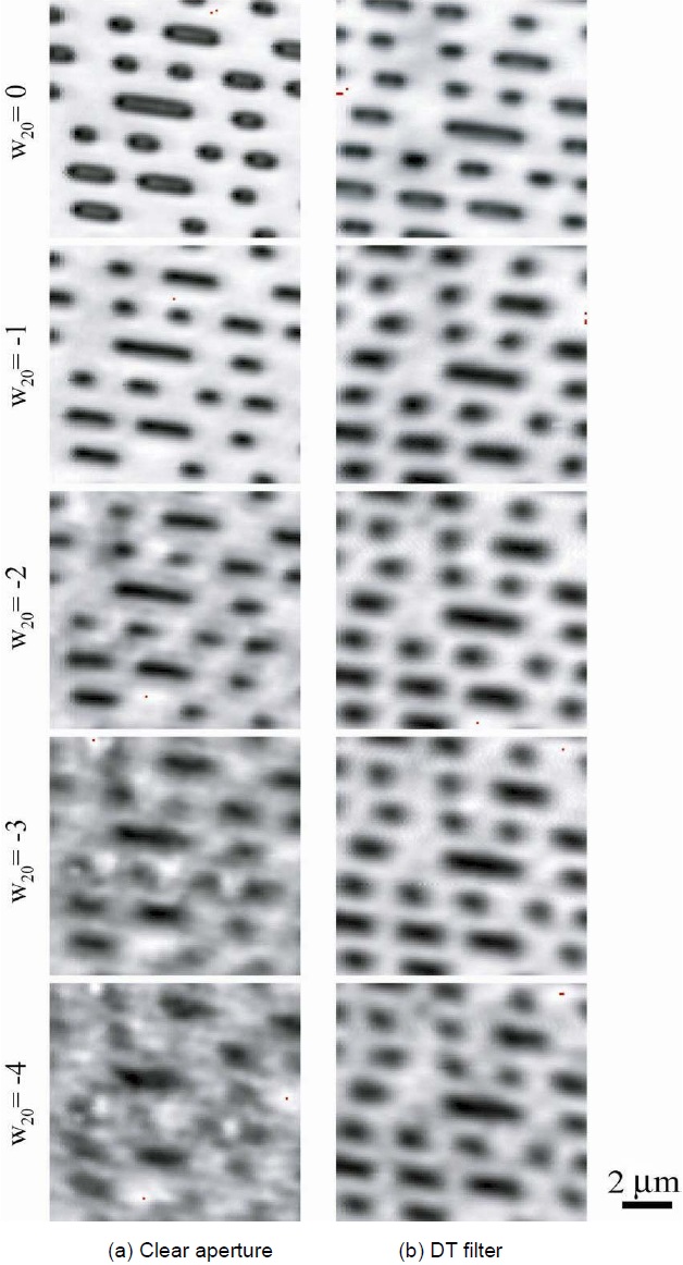
    To demonstrate the effects of defocusing in a low-NA imaging system apodized with both the clear aperture and an optimum SR filter, which is referred to as defocus tolerance (DT) filter, we prepared the experimental setup shown in Fig. 5. The DT filter was fabricated with highcontrast photographic film (Kodak Technical Pan; Rochester, NY, USA). For the illumination of a USAF 1951 resolution chart, we employed the diffused light proceeding from a white source.

    In the setup of Fig. 5, the imaging system was operated in telecentric mode and was composed of two converging lenses whose focal lengths were f1 = 400 mm and f2 = 100 mm. According to this, the resolution test was placed at the front focal plane of L1. To capture the images, we used a CCD camera (JAI/Pulnix TM-765E; Copenhagen, Denmark) composed of 765 × 578 square pixels of 11 μm on each side.

    In our experiment we recorded a set of 2D images at different axial positions, z. For simplicity, it is convenient to mount the CCD on a micrometric translation stage to provide a high-precision at different axial positions. Specifically, we selected z = 0, 2.75, 5.50, and 8.25 mm, which, according to Eq. (16), correspond to defocus coefficients of w20 = 0, -1, -2, and -3. Note that, theoretically, the PSF is symmetrical about the focal plane, so that we do not consider positive defocus parameters because we assume that we would obtain similar results.

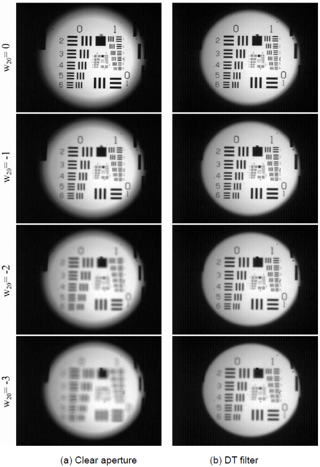
    In Figs. 6 and 7 we show the numerical and experimental results of the resolution target with the circular aperture and the DT filter. Clearly, the similarity between the experimental and calculated results is apparent. These figures also indicate that the greater the defocus coefficient, the smaller response of the clear aperture. Note that we cannot discern the low frequencies in the elements 1 and 2 of group 0 (1 and 2 LP/mm, respectively) for w20 = -3. However, the response of the DT filter remains fairly stable and for w20 = -3 it is possible to detect frequencies of 2.52 LP/mm corresponding to element 3 of group 1. Another fact to consider, in the case of a non-apodized system (left row of Fig. 7), is the contrast inversion in several elements of the test group 1 for w20 = -2.

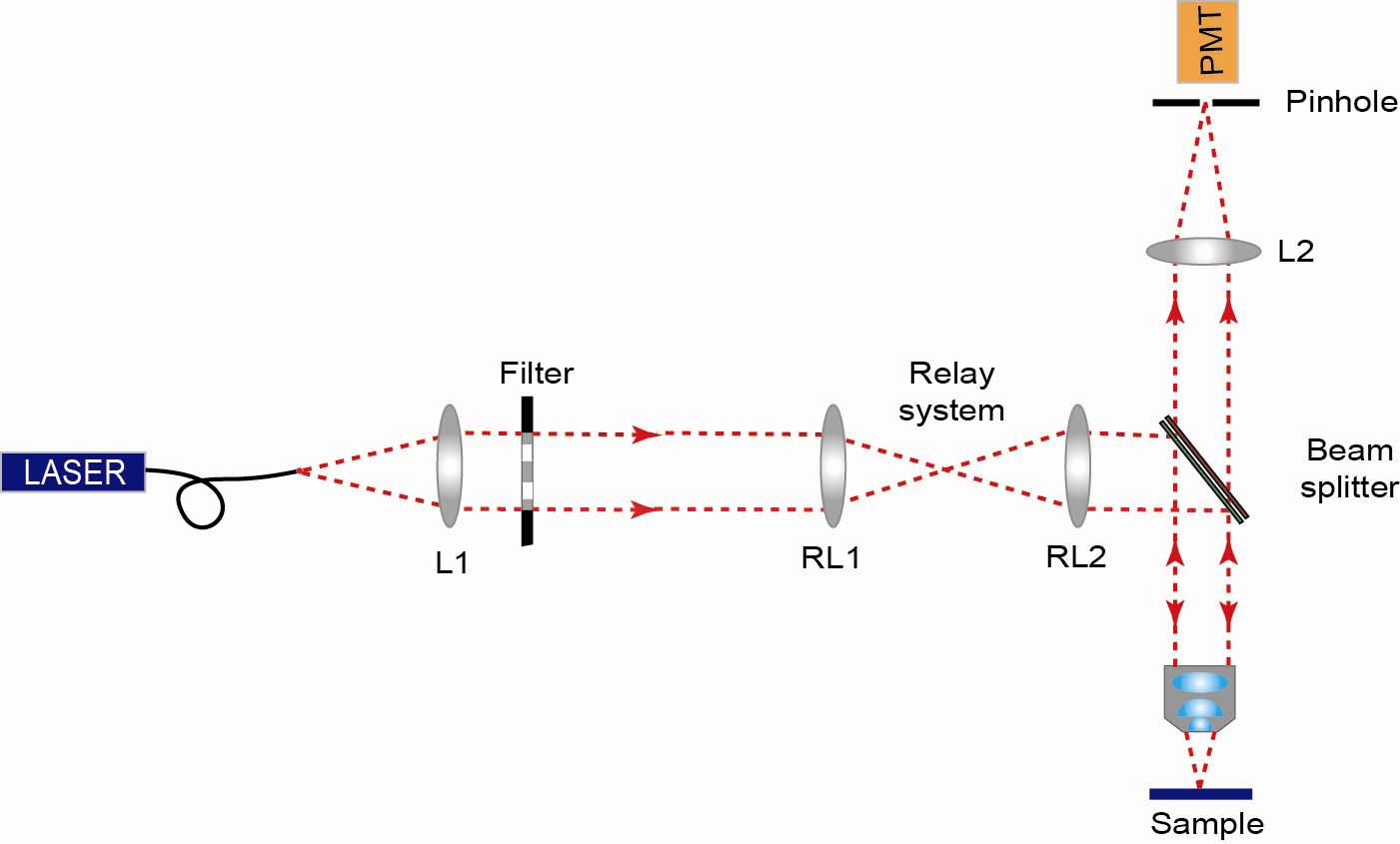
    Finally, to demonstrate the experimental case of high-NA, we arranged the experimental setup schematized in Fig. 8; this arrangement corresponds to a conventional scanning microscope. For this experiment, the light emerging from a fiber coupled to a He-Ne laser (λ = 632.8 nm) was collimated through a converging lens of focal length fL1 = 200 mm. After passing through a relay system and a beamsplitter, the wave field was focused via a microscope objective, whose NA was 0.9, onto the sample.

    The signal reflected by the sample was finally focused onto a pinhole of radius of 50 μm.

    We have carefully chosen the radius of the pinhole given that the detection was not confocal [30-33]. The pinhole was placed in front of a detector; in our case, it was a photomultiplier tube. A small fragment of an original music CD was imaged. This object was composed of a collection of tracks recorded on the CD.

    Our goal was to increase the DOF. This task can be accomplished by modifying the exit pupil with the use of a DT filter. For this purpose, we used a relay system set up from RL1 (fRL1 = 200 mm) and RL2 (fRL2 = 175 mm).

    In Fig. 9, we show the experimental results. In this case, an increase in one unit in w20 value corresponds to an axial displacement of z = 1.12 μm. Again we can see that the DT filter provides very stable behavior as the defocus parameter increases. The DT filter significantly improves the image quality from values superior to -2.

    V. CONCLUSIONS

    In summary, in this work it has been shown that the DOF has been increased in an imaging system affected by spherical aberration. This result opens the way to reducing the defocus in an imaging system by using an amplitude filter designed firstly to reduce spherical aberration. The improvement of DOF has been checked with an optimized SR filter (called a DT filter), which has been implemented in two types of experimental architecture. It should be noted that in both experiments, the DT filter provides very stable behavior compared to the clear aperture.

참고문헌
  • 1. Zhou S., Zhou C. 2004 “Discrete continuous-phase superresolving filters” [Optics Letters] Vol.29 P.2746-2746 google cross ref
  • 2. Yun M., Liu L., Sun J., Liu D. 2005 “Three-dimensional superresolution by three-zone complex pupil filters” [Journal of the Optical Society of America A] Vol.22 P.272-277 google cross ref
  • 3. Gundu P. N., Hack E., Rastogi P. 2005 “Apodized superresolution concepts and simulations” [Optics Communications] Vol.249 P.101-107 google cross ref
  • 4. Pereira S. F., van de Nes A. S. 2004 “Superresolution by means of polarization, phase and amplitude pupil masks” [Optics Communications] Vol.234 P.119-124 google cross ref
  • 5. Canales V. F., de Juana D. M., Cagigal M. P. 2004 “Superresolution in compensated telescopes” [Optics Letters] Vol.29 P.935-937 google cross ref
  • 6. Caballero M. T., Andres P., Pons A., Lancis J., Martinez-Corral M. 2005 “Axial resolution in two-color excitation fluorescence microscopy by phase-only binary apodization” [Optics Communications] Vol.246 P.313-321 google cross ref
  • 7. de Juana D. M., Oti J. E., Canales V. F., Cagigal M. P. 2003 “Transverse or axial superresolution in a 4Pi-confocal microscope by phase-only filters” [Journal of the Optical Society of America A] Vol.20 P.2172-2178 google cross ref
  • 8. Liu L., Liu C., Howe W. C., Sheppard C. J. R., Chen N. 2007 “Binary-phase spatial filter for real-time swept-source optical coherence microscopy” [Optics Letters] Vol.32 P.2375-2377 google cross ref
  • 9. Jia J., Zhou C., Liu L. 2003 “Superresolution technology for reduction of the far-field diffraction spot size in the laser freespace communication system” [Optics Communications] Vol.228 P.271-278 google cross ref
  • 10. Ojeda-Castaneda J., Ledesma S., Gomez-Sarabia C. M. 2013 “Hyper Gaussian windows with fractional wavefronts” [Photonics Letters of Poland] Vol.5 P.23-25 google
  • 11. Diaz F., Goudail F., Loiseaux B., Huignard J. P. 2009 “Design of a complex filter for depth of focus extension” [Optics Letters] Vol.34 P.1171-1173 google cross ref
  • 12. Golub M. A., Shurman V., Grossinger I. 2006 “Extended focus diffractive optical element for Gaussian laser beams” [Applied Optics] Vol.45 P.144-150 google cross ref
  • 13. Liu L., Diaz F., Wang L., Loiseaux B., Huignard J. P., Sheppard C. J. R., Chen N. 2008 “Superresolution along extended depth of focus with binary-phase filter for the Gaussian beam” [Journal of the Optical Society of America A] Vol.25 P.2095-2101 google cross ref
  • 14. Sheppard C. J. R. 2011 “Binary phase filter with a maximally-flat response” [Optics Letters] Vol.36 P.1386-1388 google cross ref
  • 15. Sheppard C. J. R., Mehta S. 2012 “Three-level for increased depth of focus and Bessel beam generation” [Optics Express] Vol.20 P.27212-27221 google cross ref
  • 16. Sheppard C. J. R. 2013 “Pupil filter for generation of light sheets” [Optics Express] Vol.21 P.6339-6345 google cross ref
  • 17. Castro A., Ojeda-Castaneda J., Lohmann A.W. 2006 “Bow-tie effect: differential operator” [Applied Optics] Vol.45 P.7878-7884 google cross ref
  • 18. Zalevsky Z., Shemer A., Zlotnik A., Eliezer E. B., Marom E. 2006 “All-optical axial super resolving imaging using a low-frequency binary-phase mask” [Optics Express] Vol.14 P.2631-2643 google cross ref
  • 19. Ojeda-Castaneda J., Tepichin E., Diaz A. 1989 “Arbitrarily high focal depth with a quasioptimum real and positive transmittance apodizer” [Applied Optics] Vol.28 P.2666-2670 google cross ref
  • 20. Hammond C. M. Jr 2000 “Apparatus and method for reducing imaging errors in imaging systems having an extended depth of field” google
  • 21. Miller D., Blanco E. 2003 “System and method for increasing the depth of focus of the human eye” google
  • 22. Ben-Eliezer E., Marom E., Konforti N., Zalevsky Z. 2005 “Experimental realization of an imaging system with an extended depth of field” [Applied Optics] Vol.44 P.2792-2798 google cross ref
  • 23. Sheppard C. J. R., Gu M. 1993 “Imaging by a high aperture optical system” [Journal of Modern Optics] Vol.40 P.1631-1651 google cross ref
  • 24. Debye P. 1909 “Der lichtdruck auf kugeln von beliebigem material” [Annalen der Physik] Vol.335 P.57-136 google cross ref
  • 25. Born M., Wolf E. 1999 Principles of Optics google
  • 26. Sheppard C. J. R., Matthews H. J. 1987 “Imaging in high-aperture optical system” [Journal of the Optical Society of America A] Vol.4 P.1354-1360 google cross ref
  • 27. Escobar I., Saavedra G., Martinez-Corral M., Lancis J. 2006 “Reduction of the spherical aberration effect in high-numericalaperture optical scanning instruments” [Journal of the Optical Society of America A] Vol.23 P.3150-3155 google cross ref
  • 28. Martinez-Corral M., Saavedra G. 2009 “The resolution challenge in 3D optical microscopy” [Progress in Optics] Vol.53 P.1-68 google
  • 29. Escobar I., Sanchez-Ortiga E., Saavedra G., Martinez-Corral M. 2011 “New analytical tools for evaluation of spherical aberration in optical microscopy” [in Optical Fluorescence Microscopy: from the Spectral to the Nano Dimension] P.85-99 google
  • 30. Wilson T., Carlini A. R. 1988 “Three-dimensional imaging in confocal imaging-systems with finite sized detectors” [Journal of Microscopy] Vol.149 P.51-66 google cross ref
  • 31. Kimura S., Munakata C. 1990 “Dependence of 3-D optical transfer functions in the pinhole radius in a fluorescent confocal optical microscope” [Applied Optics] Vol.29 P.3007-3011 google cross ref
  • 32. Gu M., Sheppard C. J. R. 1993 “Effects of a finite-sized pinhole on 3D image formation in confocal two-photon fluorescence microscopy” [Journal of Modern Optics] Vol.40 P.2009-2024 google cross ref
  • 33. Gauderon R., Sheppard C. J. R. 1999 “Effect of a finite-size pinhole on noise performance in single-, two-, and three-photon confocal fluorescence microscopy” [Applied Optics] Vol.38 P.3562-3565 google cross ref
OAK XML 통계
이미지 / 테이블
  • [ Fig. 1. ]  Conceptual diagram to explain the focus process in a high numerical aperture objective into two media separated by a planar interface.
    Conceptual diagram to explain the focus process in a high numerical aperture objective into two media separated by a planar interface.
  • [ Fig. 2. ]  Schematic of a two-dimensional telecentric imaging system. The light emanating from the object is collected by the objective (L1) and focused by the tube lens (L2).
    Schematic of a two-dimensional telecentric imaging system. The light emanating from the object is collected by the objective (L1) and focused by the tube lens (L2).
  • [ Fig. 3. ]  (a) Shaded ring filter for reduction of the spherical aberration impact, (b) Cartesian version of the filter.
    (a) Shaded ring filter for reduction of the spherical aberration impact, (b) Cartesian version of the filter.
  • [ Fig. 4. ]  Structure of the optimized shaded ring filter, called the defocus tolerance filter, which increases the depth-of-field. The two construction parameters are μ = 0.4 and η = 0.7.
    Structure of the optimized shaded ring filter, called the defocus tolerance filter, which increases the depth-of-field. The two construction parameters are μ = 0.4 and η = 0.7.
  • [ Fig. 5. ]  Conceptual experiment to demonstrate the extended field of view in a low numerical aperture imaging system. The defocus tolerance filter is placed at the front focal plane of L1.
    Conceptual experiment to demonstrate the extended field of view in a low numerical aperture imaging system. The defocus tolerance filter is placed at the front focal plane of L1.
  • [ Fig. 6. ]  Numerically-evaluated results corresponding to (a) the clear aperture and (b) the defocus tolerance (DT) filter for different values of the defocus coefficient w20. As shown in the right column, the improvement with the depth-of-field is apparent.
    Numerically-evaluated results corresponding to (a) the clear aperture and (b) the defocus tolerance (DT) filter for different values of the defocus coefficient w20. As shown in the right column, the improvement with the depth-of-field is apparent.
  • [ Fig. 7. ]  Experimental results of a resolution chart corresponding to (a) the clear aperture and (b) the defocus tolerance (DT) filter. It is clear that the response of the DT filter remains fairly stable, and it is possible to detect higher frequencies with it.
    Experimental results of a resolution chart corresponding to (a) the clear aperture and (b) the defocus tolerance (DT) filter. It is clear that the response of the DT filter remains fairly stable, and it is possible to detect higher frequencies with it.
  • [ Fig. 8. ]  Schematic layout of practical implementation of a conventional scanning microscope. The special feature of such an arrangement is the insertion of a relay system, which makes possible the introduction of an apodized filter.
    Schematic layout of practical implementation of a conventional scanning microscope. The special feature of such an arrangement is the insertion of a relay system, which makes possible the introduction of an apodized filter.
  • [ Fig. 9. ]  Experimental verification of an extended depth-of-field for a high numerical aperture scanning microscope. For the measurement, we used the tracks on a CD as the object. (a) Clear aperture, (b) the defocus tolerance (DT) filter.
    Experimental verification of an extended depth-of-field for a high numerical aperture scanning microscope. For the measurement, we used the tracks on a CD as the object. (a) Clear aperture, (b) the defocus tolerance (DT) filter.
(우)06579 서울시 서초구 반포대로 201(반포동)
Tel. 02-537-6389 | Fax. 02-590-0571 | 문의 : oak2014@korea.kr
Copyright(c) National Library of Korea. All rights reserved.