Soon, the information super highway, which is based on high speed networks, will be able to deliver a greater amount of information to each individual. It is expected that it will develop from the present method of delivery of multimedia services through a digital terminal, into threedimensional (3D) multimedia services that users see more naturally and enjoy with a more realistic sensory experience through a 3D terminal. A number of techniques including stereoscopy, holography, and integral imaging are being researched and developed actively to accomplish this goal.
Among these 3D techniques, integral imaging is drawing a great deal of attention. Integral imaging, also known as integral photography, was first proposed by Lippmann [1] in 1908. It is regarded as one of the most attractive approaches because of advantages such as full-color and real-time display of a 3D image within a certain continuous viewing angle without any supplementary devices [2-8].
In general, integral imaging consists of two processes: pickup and reconstruction. In the pickup process, information on the rays coming from 3D objects is spatially sampled by using a lenslet array, and the sampled information is referred to as an elemental image array (EIA), which is captured by a 2D image sensor, such as a chargecoupled device. The other method is the computational pickup, in which elemental images from a virtual 3D object are digitally generated using a computer simulation model of ray optics.
For the reconstruction process, there are also two types of reconstruction methods, optical integral imaging reconstruction (OIIR) [2-5] and computational integral imaging reconstruction (CIIR) [6-10]. In OIIR, images of 3D objects are optically reconstructed from the picked-up elemental images by the combined use of a display panel and a lenslet array. On the other hand, in CIIR, 3D object images can be computationally reconstructed using a digital simulation model of geometrical optics. That is, CIIR allows us to reconstruct a set of depth-dependent plane object images along the output plane through a virtual lenslet (or pinhole) array [14-18].
In computational integral imaging (CII), the pickup process is replaced by an image process [13]. Elemental images (EIs) of CII are generated from the 3D object, considering the characteristics of the virtual system that will be used in the display process. The computational pickup process is based on ray-optics, which has the benefit over the real optical pickup process of being free from the diffraction patterns of the elemental lens. Each lens in the lens array has its own image region on which the corresponding information is recorded or displayed.
In 2002?2004, the advanced three-dimensional television system technologies (ATTEST) project was carried out in Europe to apply stereoscopic 3DTV to the actual broadcasting environment [13]. In this project, a 3DTV system was designed to be completely compatible with commercial digital TV by means of 2D video and synchronized depth information, and as a result, this system could be used in an actual broadcasting environment. A technique for transmitting these 2D videos and synchronized depth information through the Digital Video Broadcasting network was also developed in this project. In the pickup part of this 3DTV system, the image and depth information of 3D objects were recorded and transmitted. Thus a technique for creating elemental images from the recorded 3D information might be a much more important factor which can applying to the difference types of integral imaging system.
Although recently developed computer processors can generate elemental images in a short time, the time needed to generate elemental images is crucial in real applications of integral imaging. In this paper, an accelerated generation algorithm (AGA) for the EIA in a computational integral imaging system is proposed. Elemental images were generated using depth information that could be generated by a depth camera or extracted from the stereo images picked up by a stereo camera. From the experimental results, it was confirmed that the proposed AGA for generating an EIA could be more efficiently used in the practical image processing area of an integral imaging system.
II. REVIEW OF EXISTING ALGORITHMS
The simple scheme for generating elemental images is to project points that compose surfaces of objects onto a pickup plane through a pinhole camera. The operation of the projection changes the coordinates of the object into the coordinates of a projection plane. That is, the ray from a point of the object penetrating the center of elemental lenses is recorded in the pickup plane under the ray-optics assumption. This way of generating elemental images is called the direct algorithm (DA) and the detailed pseudo code of DA is as follows [11].
Direct Algorithm
1 g = distance_between_lens_and_pickup_plane
2 For every_object : from_the_furthest
3 L = distance_between_object_and_lens
4 For every_pixel_in_the_object
5 (x, y) = physical_location_of_a_pixel
6 For every_elemental_lens
7 (cX, cY) = center_of_the_elemental_lens
8 sX = cX + (cX-x)*g/L
9 sY = cY + (cY-y)*g/L
10 If
11 |sX-cX| < half_lens_pitch && |sX - cY| < half_lens_pitch
12 (iX, iY) = index_of_(sX, sY)_in_the_ EI
13 save_the_color_of_the_pixel_at_(iX, iY)
14 End If
First, calculate the physical distance to the surfaces of an object. In the case of depth information, we consider the pixel points of the 3D object at the same physical distance. Second, calculate the physical locations for every pixel comprising the surfaces of the object. Third, by using precalculated center locations of all elemental lenses, determine the locations where rays from the pixel location of the object should be focused on the pickup plane. Fourth, check whether the locations in focus are inside the image region of each elemental lens. Finally, convert the locations in focus to the pixel index of the elemental images and record the information.
Because we must watch the nearest object in the display process when multiple objects overlap, this algorithm must be executed on the furthest object first. Moreover several pixels of the object can be recorded over the same location as the elemental images, which is a wasteful calculation. This algorithm depends on the total number of pixels comprising the surfaces of the object. Thus if the number of pixels in the objects is N, the time complexity is
1 g = distance_between_lens_and_pickup_plane
2 centerX = x_coordinate_of_first_elemental_lens
3 boundX = centerX + half_lens_pitch
4 For every_x_in_the_EI: from_left_to _right
5 If x > boundX
6 centerX = centerX + lens_pitch
7 boundX = boundX + lens_pitch
8 End If
9 centerY = y_coordinate_of_first_elemental_lens
10 boundY = centerY + half_lens_pitch
11 For every_y_in_the_elemental_images: from_ bottom_to_top
12 If y > boundY
13 centerY = centerY + lens_pitch
14 boundY = boundY + lens_pitch
15 End If
16 For every_object : from_the_nearest
17 L = distance_between_object_and_lens
18 sX = centerX +(centerX-x)*g/L
19 sY = centerY +(centerY-y)*g/L
20 If (sX, sY)_is_inside_the_object
21 sample_the_color_of_(sX, sY)_in_the _object
22 break_innermost_for_loop
23 End If
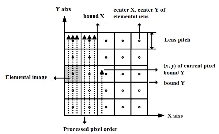
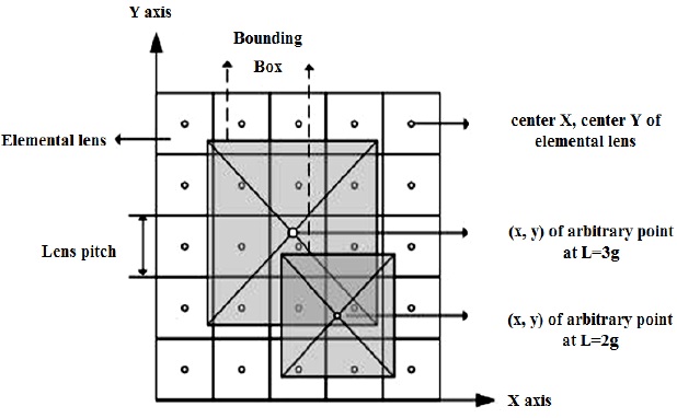
The basic concept of the efficient algorithm (EA) [12] is shown graphically in Fig. 1. First, calculate the physical location of a current pixel of the elemental images. Second, find the center location of the elemental image whose image region includes the current pixel. Third, check if the ray that penetrates the center of the current elemental lens from the current pixel meets an object under the ray-optics assumption. This checking process must be done from the nearest object to the furthest object and must stop the process if we find a matched point. Finally, if you find the matched point in an object, convert the physical location to the pixel index of elemental images and record the color information to it.
Because we must watch the nearest object in the display process when multiple objects overlap, this algorithm must be executed on the nearest object first. This algorithm depends on the total number of pixels consisting of elemental images. Thus if the number of pixels in elemental images is M, the time complexity is The authors also introduced the concept of additional algorithms for optimal sampling. This is based on the fact that a pixel of an elemental image has a finite size and it corresponds to the demagnify part of the 3D object. Then they proposed the EA and DA for optimal sampling. It is necessary to consider optimal sampling in the CII in which the pickup process is performed in the computer instead of optically. However, it must not be considered in our problem because it is already considered when generating color image and depth information.
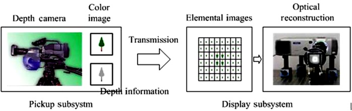
In this paper, we propose an integral imaging display system that accepts real 2D color image and depth information, as shown in Fig. 2. The pickup system generates real 2D color image and depth information. This will be transmitted through the network to the display subsystem. The display system generates the elemental images according to their characteristics and optically reconstructs integral images using it. In the proposed integral imaging system, our object is to generate elemental images as fast as possible for the realtime TV or video system.
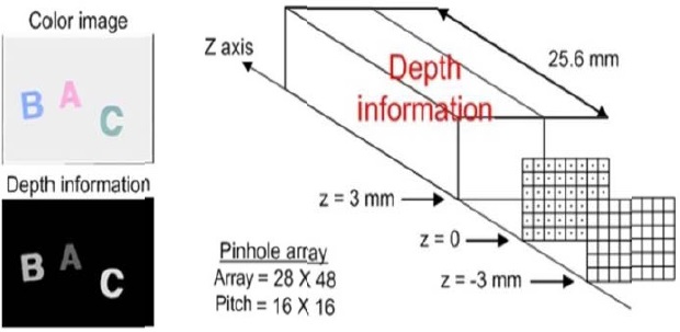
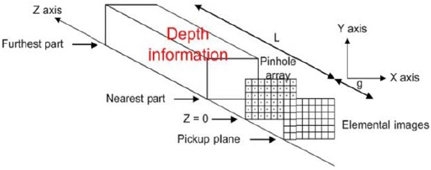
Given the color image and depth information, consider how to generate elemental images. The conceptual structure for generating elemental images from depth information looks like Fig. 3. At first, the pinhole array is placed at the z = 0 position. In the computational integral imaging system, we use the pinhole array for making simple calculations. Also, place the pickup plane of the elemental images at the z = -g position. Then place the nearest part of the depth information near and the furthest part of the depth information far along the z axis. After completing the placement of these, we can generate elemental images using ray-optics.
Therefore, the problem is to generate elemental images from the color image and depth information. That is, the proposed problem is to generate elemental images from the 3D object that consists of the color image and depth information. It is different from generating elemental images in CII in which the pickup process is performed in the computer instead of optically. The situation is different but the target to generate elemental images is the same.
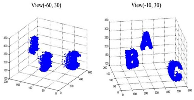
Fig. 4 shows the depth information of the 3D object by obtained from the depth camera, which are A, B, and C characters. As can be seen, it consists of points on the surfaces of objects. Thus in the depth information, we can regard points with the same physical distance as surfaces of objects for image processing regardless of the shape of the actual objects. If the depth information is expressed as a grayscale image, we can think of it as an object that has 256 surfaces.
Now that the depth information has been introduced, we will apply the existing algorithms to it. In the case of the EA, it is a very difficult and time-consuming job to check whether the ray that penetrates the center of the current elemental lens from the current pixel meets an object. Therefore, in the case in which surfaces are perpendicular to the z axis and the number of surfaces is small, the EA can be efficient. However, in the case of depth information, it is not efficient because the checking problem is difficult. Therefore, we do not apply the EEA to the depth information.
In the case of the DA, we can apply it to the depth information because points that consist of surfaces on the object are projected onto the pickup plane through the pinhole camera. Also, in this case, it seldom occurs that several pixels of objects are overwritten on one pixel location of the elemental images. In the DA, all points are projected through the array of all elemental lenses. If we project through some part of the elemental lenses for each point, it will be faster than the DA. This is our idea of the AGA. Before applying the AGA, some preprocessing, such as extracting all the points from the depth in formation and sorting, is required. This step is necessary in the DA, so we will compare the elemental images generation times of AGA and DA. The detailed pseudo code oof AGA is ass follows.
Accelerated Generation Algorithm
1 extract all points from the depth information
2 sort every pixel of the object from the furthest
3 g = distance_between_lens_and_pickup_plane
4 For very_pixel_of_objects: from_the_furthest
5 L=distance_between_pixel__and_lens
6 (x,y)=physical_location_of_a_pixel
7 Y_lower_boundary = y ? y_lens_pitch*L/(g*2)
8 Y_upper_boundary = y + y_lens_pitch*L/(g*2)
9 X_lower_boundary = x ? x_lens_pitch*L/(g*2)
10 X_upper_boundary = y + y_lens_pitch*L/(g*2)
11 For every_elemental_lens_in_y_direction % from_bottom_to_top
12 cY = y_center_of_the_current_elemental__lens
13 If(Y_lower_boundary 14 For every_elemental_lens_in_x_direction % from_left_to_right 15 cX = x_center_of_the_current_elemental_lens 16 If(X_lower_boundary 17 sY = cY +(cY-y)*g/L 18 sX = cX +(cX-x)*g/L 19 (iX, iY) =index_of_(sX, sY)_in_the_EI 20 save_the_color_of_the_pixel_at_(iX, iY) 21 End If 22 End If The basic concept of the AGA is shown graphically in Fig. 5. First, calculate the physical distance to the pixel of thee object. Second, calculate its physical dimensions. Therefore, we found all of the information on the voxel. Third, find thee lower and upper boundaries in the x and y directions by using the bounding box that restricts the projection. The size of the bounding box increases according to the L value inn the z direction. Fourth, check whether the center of thee elemental lenses is in the bounding box, and if so, find the matched point in the elemental images and convert the physical location to the pixel index of the elemental images and record color information to it. To verify that the AGA more efficient than the DA, suppose the number of points is n and the number of elemental lenses is p*q, where p denotes the number of rows and q denotes the number of columns. Also take operations such as “sY = cY +(cY-y)*g/L” and “Y_lower_ boundary = y ? y_lens_pitch*L/(g*2)” as unit operations. Then, the DA and AGA are require the 2npq and n(4+2c) unit operations, respectively, where the parameter c is the number of elemental lenses within the bounding box. Thus, we can conclude that the AGA is faster than the DA when c<
To test the feasibility of the proposed method, some experiments are performed with test objects composed of three 2D images. Fig. 6 shows the experimental setup for picking up the EIA in the CII system. We obtain the color images and depth information for the “ABC” characters from the depth camera. Before using the depth information, it is normalized to the grayscale.
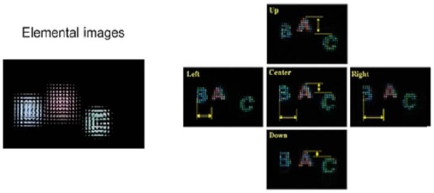
In the experiments, we generated EIAs by using the DA and AGA as shown in Fig. 7. Then, we confirmed the MSE (me an square error) of the two EIAs by using a DA and AGA of zero, which meant the two kinds of algorithms used to generate EIAs were exactly the same. The resulting optically reconstructed object images are shown in Fig. 7, each observed from 5 different viewing positions.
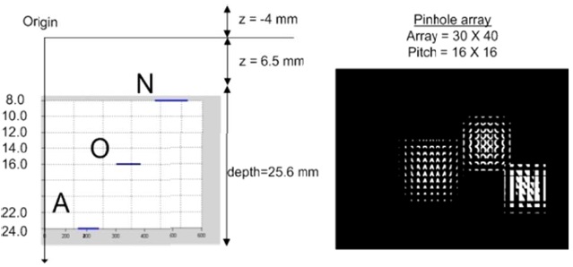
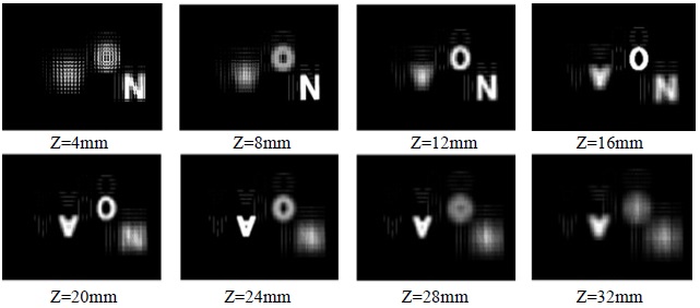
The other experiments were performed by using CIR to verify the feasibility of the proposed method. The depth information was extracted from a stereo image of the “NOA” characters and normalized to the gray scale. The experimental setup and generated EIA are shown in Fig. 8. Fig. 9 shows thee reconstructed 3D images using CIR. From the result of Fig. 9, we can determine that the N, O, and A characters are focused at z = 8, 16, and 24 mm. Thus, we can verify the feasibility of the proposed AGA.
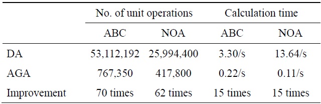
[Table 1.] Performance comparison results

Performance comparison results
Moreover, Table 1 shows the results of the performance comparison of the DA and AGA. For the case of the first experiment, the voxel number of “ABC” data was 19,759. Thus the calculated number of unit operations was 53,112,192 (2×19,759×28×48) in the DA and the measured number of unit operations was 767,350 in the AGA. That is, the simple comparison revealed that the AGA was 70 times faster than the DA. However, the measured calculation time was 3.2969 seconds in the DA and 0.2188 seconds in the AGA. Thus, we can conclude that the proposed AGA is 15 times faster than the DA. In the case of the second experiment, the voxel number of “NOA” data was 10,831. Thus the calculated number of unit operations was 25,994,400 (2×10,831×30×40) in the DA and the measured number of unit operations was 417,800 in the AGA. That is, a simple comparison reveals that the AGA is 62 times faster than the DA. At the same time, the measured calculation time was 1.6406 seconds in the DA and 0.1094 seconds in the AGA. It is finally confirmed from these results that the AGA is 15 times faster than the DA.
In this paper, a new AGA for generating EIAs in integral imaging is proposed. In the proposed method, the EIA can be generated through depth information by using the AGA. Experimental results show that in the proposed method, the number of unit operations and calculation time have been improved by 66 times and 15 times on the average, respectively, over the conventional DA.