The H.264/AVC [1] standard was developed in 2003 by the Joint Video Team (JVT) of ISO/IEC Moving Picture Experts Group (MPEG) and the International Telecommunications Union's Video Coding Experts Group (ITU-VCEG). It is a popular industry standard for video coding and has been applied to various devices, such as portable devices, remote surveillance systems, and home appliances. The reason for its adoption by industry is its coding efficiency improvement of up to 50% compared to the earlier MPEG-4 standard. Various techniques were newly introduced to improve the efficiency in the standard, such as quarter-sample-accurate motion compensation, directional spatial prediction for intra-coding and in-loop deblocking filtering. A number of studies [2-4] have been performed to enhance the performance of H.264/AVC codecs.
In intra-prediction, which utilizes the spatial correlation in an image to predict the blocks, there are 17 prediction modes in total. Each mode uses reconstructed neighboring pixels of the previously decoded blocks to compute the predicted pixels. In this paper, we focus on reducing the prediction computing cycles to improve the performance of intra-prediction. We achieved it by analyzing the great similarity among equations for generating prediction pixels across prediction modes. We also propose the memory architecture for an efficient method of intra-prediction. The proposed design targets mobile devices and utilizes the H.264/AVC baseline profile.
The rest of the paper is organized as follows. In Section II, intra-prediction is briefly introduced. In Section III, the proposed architecture and the analysis are presented. Finally, the conclusion is addressed in Section IV.
In this section, we briefly introduce intra-prediction in H.264/AVC decoding.
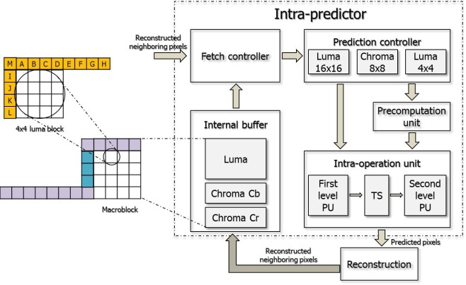
In this prediction process, image information is fetched from previously decoded adjacent pixels. The pixels are reconstructed neighboring pixels, which are used for the 17 prediction modes: 4 for a luma 16×16 block, 4 for two chroma 8×8 blocks, and 9 for a 4×4 luma block. A luma 16×16 block is predicted by using the upper, upper-left and left neighboring blocks. For a luma 4×4 block, the upper, upper-right, upper-left, and left luma blocks are used for prediction. Predicting a chroma 8×8 block is similar to predicting a luma 16×16 block; it also uses upper, upperleft, and left blocks. The number of the prediction pixels used for different types of blocks is different. For a 16×16 luma block, a 4×4 luma block, and a 8×8 chroma block, 33, 13, and 17 pixels are used for prediction, respectively. We have to consider the effective ways of load and store schemes for those neighboring pixels used for computation to improve the performance. The nine modes for a luma 4×4 block in intra-prediction are vertical, horizontal, DC, diagonal down-left, diagonal down-right, vertical-right, horizontal-down, vertical-left, and horizontal-up. The last six modes mentioned above are also called direction modes in this paper. For a luma 16×16 block and two chroma 8×8 blocks, the horizontal, vertical, DC, and plane mode are utilized. Each prediction block is generated using one of a number of prediction modes. Generating the prediction block through the computation of neighboring pixels is the main bottleneck in improving the performance in intra-prediction.
In this section, we present the proposed intra-predictor architecture. Fig. 1 shows the proposed intra-predictor hardware architecture and the arrows show the data flow excluding control signals.
As shown in Fig. 1, it consists of a fetch controller, prediction controller, precomputation unit, intra-operation unit, and internal buffer. The fetch controller logic fetches the neighboring pixels for a 16×16 macroblock from the internal buffer. After receiving the neighboring data from the fetch controller, the prediction controller transfers the exact neighboring data used for computing to the precomputation unit and intra-operation unit according to the prediction modes. The intra-operation unit computes the predicted pixels using the neighboring pixels and the precomputation unit is only used when the prediction mode is plane mode.
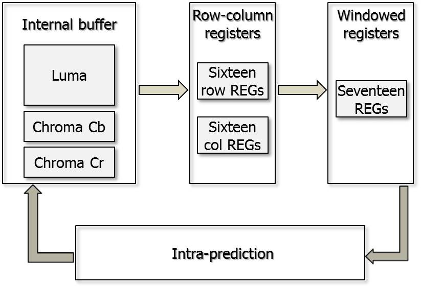
The memory architecture proposed in this paper consists of two parts: the internal buffer and neighboring pixel registers. The internal buffer is used for storing the neighboring pixels for the 16×16 macroblocks, and the registers are used for storing the neighboring pixels for each prediction mode.
The upper neighboring pixels for the current macroblock are from the macroblock in the previous row. After finishing the prediction of the current macroblock, the sixteen pixels in the last row of the current macroblock must be stored in the internal buffer for the prediction of the macroblocks in the next row. The pixels in the right-most column of the current macroblock must also be stored in storage logic. In Xu and Choy [5], they are stored in an internal memory and loaded to the column registers when they are used for prediction. However, in the proposed design, the pixels in the right-most column are stored directly in neighboring registers for the prediction of the next macroblock. In this way, the proposed design can reduce the size of the internal buffer and the memory access cycles.
Fig. 2 shows the proposed memory architecture. The proposed design contains 32 row-column registers for upper and left neighboring pixels used for a macroblock and 17
windowed registers for a 4×4 luma block. If the current macroblock is intra-predicted, the neighboring pixels will be fetched from the internal buffer and stored in the row-column registers. If the prediction mode is for a luma 4×4 block, before the computation process using the neighboring pixels starts, the pixel data in the row-column registers will be loaded to the windowed registers because the computation process is achieved in the unit of one 4×4 block at once. In the case of the 16×16 luma modes, the data in the row-column registers is directly assigned to the inputs to the intra-operation unit. The data in the right-most column is stored in the row-column registers for the prediction of the next macroblock as the prediction of the right-most 4×4 block is completed.
Before designing the prediction unit, we made an analysis of the predicted pixel derivation equations. As the equations have a number of similarities, they can be written in the form of Px + Py + z.
For the luma 4×4 block direction modes, the following forms were used in a previous design by Shim et al. [6]:


In Eqs. (1) and (2), we can observe that the added numbers 2 and 1 are used for round operations, and additional logic and cycles are needed for round operations. In the proposed design, we have eliminated round operations by using the following form:

The two 1s in Eq. (3) can be directly used as inputs to the prediction unit which can reduce the compute cycles and round logic.
For the luma 4×4 DC mode, the two chroma 8×8 DC modes, and the luma 16×16 mode, we have also applied formations similar to the one in Eq. (3).
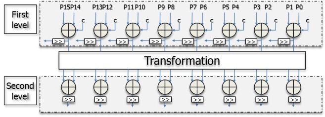
Fig. 3 illustrates the proposed parallel intra-operation unit architecture. It consists of three parts: a first level unit, a second level unit, and a transformation logic. The first level unit makes connections with the second level unit through the transformation logic according to the prediction modes. The highly parallel architecture can achieve the process using sixteen neighboring pixels in one cycle.
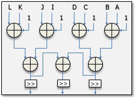
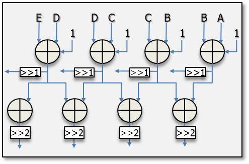
Fig. 4 shows the partial connections of the vertical-left mode for a luma 4×4 block. In this mode, the inputs are from A to G, which are the upper and upper-right neighboring pixels shown in Fig. 1. The output values of the first level unit are (A+B+1), (B+C+1), (C+D+1), (D+E+1), (E+F+1), and (F+G+1). These values form the inputs to the second level unit and the output values of the second level unit are (A+2B+C+2), (B+2C+D+2), (C+2D+E+2), (D+2E+F+2), and (E+2F+G+2). All the values are assigned to the exact positions in a luma 4×4 block after shift operations in the first level unit and the second level unit. Other direction modes make connections in the similar ways, and only one cycle is needed for the luma 4×4 direction modes.
Fig. 5 depicts the partial connections of the DC mode for a luma 4×4 block. The neighboring pixel inputs to the DC mode for a luma 4×4 block are A to D and I to L, which are
the upper and left neighboring pixels. Before assigning the predicted pixels to the right pixel positions, it should achieve the average computation process. It can compute the sum of the upper and left neighboring pixels within one cycle and assign the data after shift operation. For a luma 16×16 block, there are 32 neighboring pixels used for the computation. The unit can only achieve the computation of 16 neighboring pixels each cycle and two extra registers are needed for temporary data storage.
For the plane mode, the parameters a, b, c, H, and V are computed in advance. For eliminating the multiply operation proposed in the standard [1], we applied the algorithm introduced in [7].
A seed is computed using a, b, and c before computing the predicted pixels. The derivation of computing the parameter a, b, and c is as follows:


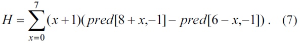
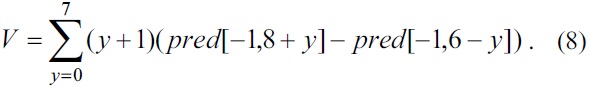
We can determine from Eq. (4)?(8) that the parameters H and V are computed in advance and used for computing the parameters a, b, and c.


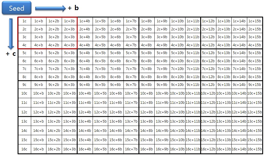
The seed in Eqs. (9) and (10) is used for pixel prediction at position (0, 0) of a 4×4 luma block. The rest of the pixels in the 4×4 block can be computed by adding b horizontally or c vertically, or both b and c, as shown in Fig. 6.
For example, the pixel values in positions (0, 1), (1, 0), and (1, 1) are seed_0 + c, seed_0 + b, and seed_0 + b + c, respectively. The seed and all the parameters are computed in the precomputation unit using only add and shift operations.
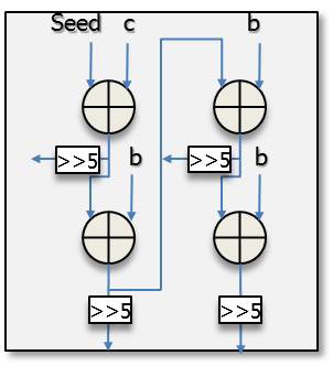
The seed, b, and c, as illustrated in Fig. 7, are precomuted in the precomputation unit. After finishing the computation of the seed, b, and c, they are transferred to the intra-operation unit and used as the inputs to the unit in the plane mode for a 16×16 luma block. It can predict four pixels in a row with the design shown in Fig. 7 and predict sixteen pixels at once since there are four similar sub architectures in the entire prediction unit.
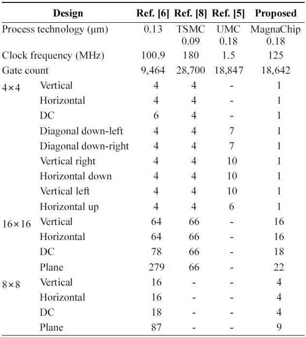
[Table 1.] Comparison of the prediction cycle for each mode

Comparison of the prediction cycle for each mode
As shown in Table 1, the proposed design was synthesized with MagnaChip 0.18 μm technology and the maximum frequency can reach 125 MHz. In Shim et al. [6], the author did not mention what technology it applied. However, the design was synthesized with a higher technology cell library and lower clock frequency, which is easier to reduce the gate count compared withsed design. The design of He et al. [8] was synthesized with higher technology and the frequency is also higher than the proposed design. However, the gate count reduction of the proposed design is 35.04% compared with the design of He et al. [8]. The gate count is also slightly reduced compared with that of Xu and Choy [5]. The proposed architecture reduces the number of cycles by up to 89.66% compared with the designs in [5,6,8] and the average cycle reduction ratio is 78.01%.
In this paper, we proposed a highly parallel intra-operation unit and a memory architecture for improving the performance of intra-prediction. The process for a luma 4×4 block can be achieved in one clock cycle in the proposed architecture. The proposed architecture was designed with Verilog hardware description language (HDL), and synthesized with the Magna- Chip 0.18 μm library. The maximum frequency of the proposed design can reach 125 MHz. As a result of the experiment, the average cycle reduction ratio is 78.01% compared with the previous works and the gate count is also reduced compared with the design synthesized with 0.18 μm technology.