The lasing mechanism of a frequency-shifted feedback (FSF) laser (FSFL) is somewhat different from that of a conventional laser because it is formed by successive frequency shifts of the spectral components of the cavity modes [1]. This means that in terms of the spectral cavity mode, it cannot have a steady-state condition. As a result, one can obtain a variety of unique and distinctive lasing properties from these types of lasers. Therefore, FSFLs have been investigated as coherent light sources for various applications, such as broadband continuous-wave (CW) lasers [1,2], multiwavelength lasers [3-5], and pulsed lasers [6-12]. In general, the FSF mechanism is obtained by an acousto-optic modulator (AOM), either an upshifting or downshifting type, inserted in the laser cavity. (It should be noted that the function of the AOM in the cavity is not for the amplitude modulation of the cavity modes but for their continuous frequencyshift.)
In particular, stable mode-locked pulses can also be generated from FSFLs, and pulse durations obtained with them are typically in the order of tens of picoseconds [6-9]. To date, most experimental investigations of FSFLs have focused on achieving shorter pulses through modifying cavity configurations [10-12], or by combining the FSF mechanism with other mode-locking techniques, e.g., nonlinear polarization rotation [10,12]. Such novel configurations were able to reduce pulse durations to a few picoseconds or hundreds of femtoseconds. An interesting feature commonly observed in FSFLs is that their pulse durations can also be extended to a few hundred picoseconds or sub-nanoseconds via the formation of bound multiple-trailing pulses [9], thereby being capable of pulse-energy scaling. However, in such sub-nanosecond regimes, the bound multiple-trailing pulses tend to have non-negligible splits among the internal pulses, giving rise to strong internal modulation across the whole group of pulses [9]. It should be noted that the mechanism of the bound multiple-trailing pulses in FSFL regimes is far different from that of bunching of random pulses in noise-like pulse regimes [13,14]. Here, we investigate an all-fiberized FSFL that can generate sub-nanosecond mode-locked pulses having no internal pulse-separations by means of incorporating a bandpass filter (BPF) of a narrow bandwidth. As a result, the bound pulses form a single-entity envelope of an asymmetric Gaussian shape, which is in agreement with the theoretical prediction previously reported [13], while we consider that the cavity dispersion also plays an important role in forming the asymmetry. We found that this type of pulse can also offer good power scalability via broadening the pulsewidth while increasing pump power. In the following section we discuss its detailed experimental demonstration and analysis.
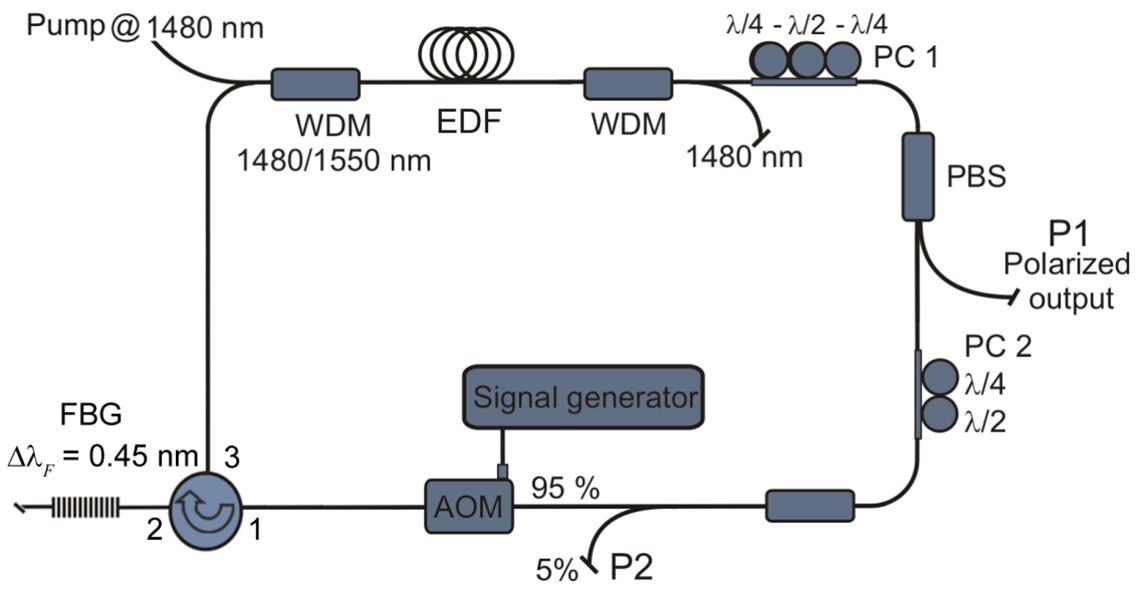
The schematic of the all-fiberized FSFL is shown in Fig. 1. It consists of 2-m of an erbium-doped fiber (EDF, Fibercore) that has a small-signal absorption rate of 37 dB/m at 1530 nm. It is pumped by two laser diodes (LDs) at 1480 nm through a wavelength-division-multiplexed (WDM) coupler (1480/1550 nm). A second WDM coupler spliced at the other end of the EDF removes the unabsorbed pump light from the cavity. The combination of two sets of polarization controllers (PCs, PC1 and PC2) and a fiberized polarization beam splitter (PBS) are utilized to introduce the phase bias required to lock the longitudinal modes of the ring cavity and to adjust the output coupling ratio (OCR) of the cavity. PC1 and PC2 consist of three wave plates (
and 200-MHz AOMs, respectively. The AOMs are driven by a radio-frequency (RF) signal generator. In addition, the cavity incorporates a BPF, which is based on a uniform fiber Bragg grating (FBG) with a spectral bandwidth (
When the cavity shown in Fig. 1 was initially tested without incorporating the AOM, it was completely impossible to make the laser mode-locked at any pump power level up to 250 mW in the given condition. This indicates that the saturable absorber effect induced by the nonlinear polarization evolution combined with the PBS in the cavity was not strong enough to generate mode-locked pulses, thereby only forming noisy, random pulses in the time domain. On the contrary, when the 110-MHz AOM was incorporated in the cavity, mode-locked pulses were readily achieved. It is worth mentioning that the laser was set to operate in the non-resonant regime since mode-locking was achieved more easily and kept with higher stability. This means that the driving frequency of the AOM was detuned from a harmonic of the fundamental cavity resonance frequency [9].
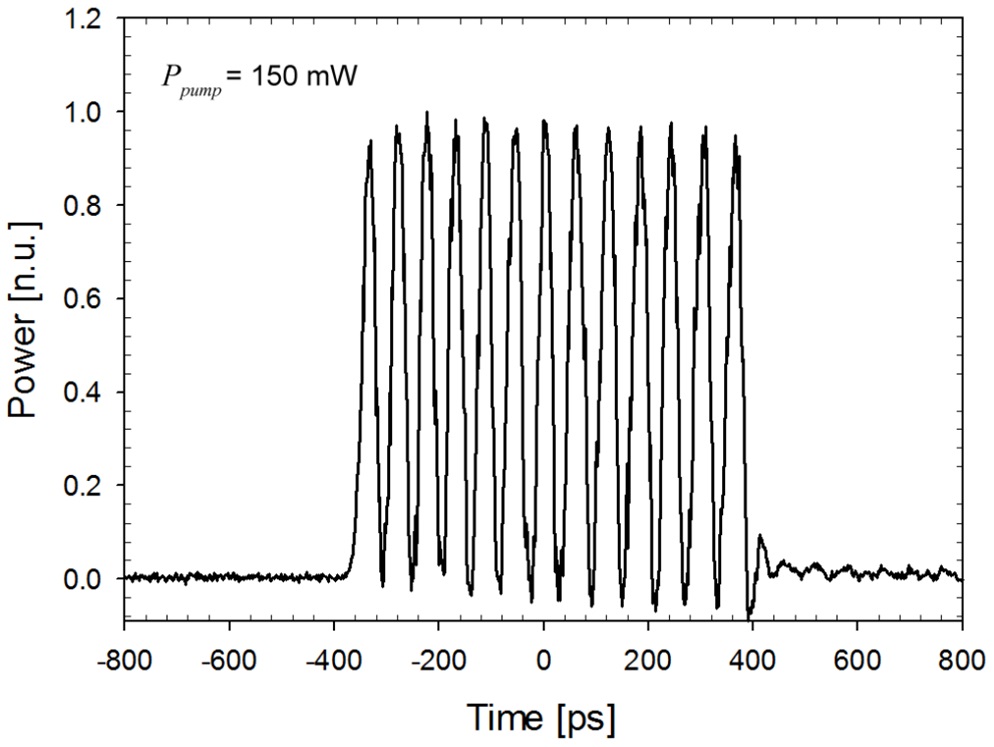
Figure 2 shows a typical output pulse formation when
the laser was operating in a multiple-pulse mode-locked (MPML) regime where an in-line BPF having a filter bandwidth of 1.3 nm, instead of 0.45 nm, was utilized in the cavity similar to the one shown in Fig. 1. In this regime, the laser presented self-starting mode-locked behaviors for pump powers in excess of 150 mW, and the number of the bound consecutive pulses increased with pump power. However, as can be seen in Fig. 2, the consecutive pulses could not form a single-entity envelop. In fact, the formation of these multiple pulses resembles the soliton-mode-locked regimes operating with excessive gain [9]. Since the net dispersion of the cavity is in the anomalous regime, we attribute the formation of the bound consecutive pulses to quasi-soliton formation in the cavity section where dispersion is anomalous. In this case the self-phase modulation (SPM) plays an important role in forming the pulse, and, thus, we expect that the peak power and pulse shape basically follow the soliton-area theorem [15]. Consequently, consecutive quasisoliton pulses cannot join together because of the strong soliton interaction between them [13,16], thereby resulting in a clear pulse separation between them. Therefore, in order for the FSFL to operate in a consolidated-pulse mode-locked (CPML) regime having no internal pulse separations, the SPM effects must be substantially alleviated unless the dispersion characteristic of the cavity is altered. For this purpose, we reduce the filter bandwidth, which can subsequently decrease the instantaneous intensity of the resultant pulse via hindering the formation of short pulses in the cavity. Here, we utilized the FBG with spectral bandwidth of 0.45 nm (FWHM) in the cavity, as described earlier in this section.
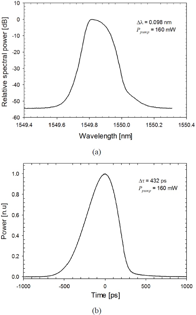
With incorporating the FBG-based BPF, we observed self-starting, fundamental mode-locked pulses (
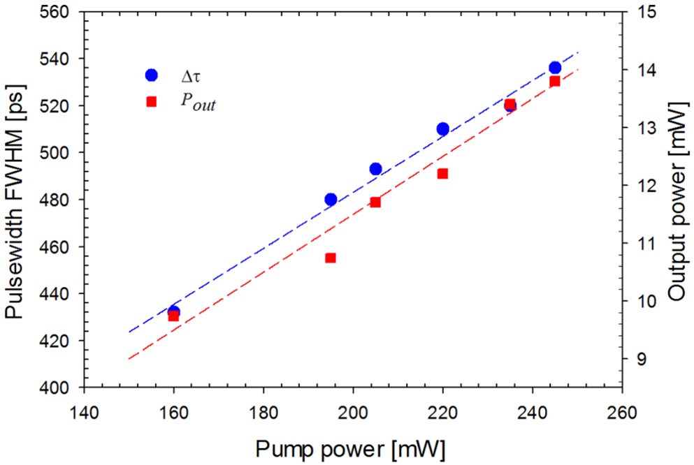
In addition, we could see that the pulsewidth of the consolidated pulse as well as its pulse-energy was scaled with pump power. The pulsewidth and average output power as a function of the pump power are shown in Fig. 4, which indicate a good linearity with respect to the pump power. The pulse-energy is readily obtained via dividing the average output power by the repetition rate of 8.51 MHz as the background amplified spontaneous emission (ASE) was negligible. Since the maximum output power was limited by the maximum pump power used, which was ~250 mW, we expect that further power scaling will be possible if higher pump power is launched in the cavity. It is also
worth mentioning that once the laser was mode-locked, it was possible to keep the laser operating in the CPML regime while decreasing the pump power down to ~160 mW. Below this value, mode-locking was no longer supported in the cavity. When the mode-locking was lost for the pump power of less than ~160 mW, the laser could not be mode-locked again until the pump power was set to in excess of 200 mW. In fact, this pump-power hysteresis is a common feature observed in FSF mode-locked lasers [9,17]. In addition, fundamental mode-locking was always achieved for any polarization states and pump powers, and no harmonic mode-locking was observed.
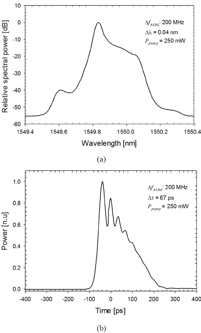
For comparison, Fig. 5 shows the pulse spectrum and time trace characteristics of the FSFL when a 200-MHz downshifting AOM was incorporated into the cavity instead of the 110-MHz AOM. This shows significantly different lasing behaviors compared to those with the 110-MHz AOM. Modelocking was only obtained for the pump power of ~250 mW in this configuration. The significant increase of the self-starting threshold was due mainly to the 4-dB of the excessive loss of the 200-MHz AOM in comparison with that of the 110-MHz AOM. It is noteworthy that in this configuration there is a clear, half-separation between the consecutive pulses. The pulse spectrum formed a main peak with a spectral bandwidth of 0.04 nm and a broad shoulder on the longer wavelength side that is ~10 dB below the level of the spectral maxima. We consider that this lasing regime is somewhat different from that observed in the previous case. We attribute the excessive loss of the AOM, together with the increment in the frequency-shift quantity, to the reduced amplification of the spectral components located on the longer wavelength side of the spectrum. Thus, the shoulder formed on the longer-wavelength side remained ~10-dB lower than the spectral maxima. Consequently, it could not form a complete, consolidated bound state having a single-entity envelope as seen in Fig. 3(b).
We have presented an all-fiberized, power-scalable, selfstarting sub-nanosecond mode-locked laser, which was based on a frequency-shifted-feedback ring cavity incorporating 2.3 m of an EDF, a 110-MHz downshifting AOM, and a BPF of 0.45 nm (FWHM). Different from conventional MPML FSFLs, it could operate in the CPML regime and deliver an output power of 9 to 16 mW as proportional to pump power. The consolidated pulse with a single-entity envelope was formed thanks primarily to the inclusion of the BPF of 0.45-nm bandwidth into the cavity, which effectively hindered the formation of quasi-soliton pulses. Based on our experiment, the CPML regime was obtained when the bandwidth of BPF was 4 to 5 times broader than the spectral bandwidth of the laser signal. However, we are aware that this condition may change based on other parameters of the laser cavity, including the transfer function of the BPF, the frequency-dependent loss in the cavity, the dispersion of the cavity, the inversion level of the gain medium, etc. In the anomalous dispersion regime having negligible SPM effects, the continuously downshifted components undergo gradually elongated cavity round-trip times, so that they are successively accumulated in the trailing edge. This consequence, together with the balancing of gain and loss incurred by the EDF and BPF [13], leads to the asymmetries observed in the spectral and temporal shapes of the resultant pulse. The developed FSFL can have further power-scaling as well as pulse-energy scaling if higher pump is launched in the cavity. This can also be utilized as a masteroscillator for a power amplification system for achieving high-energy pulses.