Wavelength-tuning capability in NIR lasers is attractive for multi-wavelength biomedical applications. In a diffuse optical tomography system, multiple light sources with different wavelengths could be replaced by a single tunable laser [1]. Spectral-domain optical coherence tomography requires lasers with widely tunable wavelengths to obtain 3D tissue images [2]. For detecting oxygen concentration carried by hemoglobin, spectral response depending on the oxy-hemoglobin concentration is obtainable with a single tunable laser [3].
Tunable lasers with external feedback of certain wavelengths have been widely investigated based on a subwavelength grating mirror [4], a flexible membrane reflector [5], and a rotating broadband mirror associated with a dispersive prism [6]. An external cavity laser (ECL) with a polymer waveguide Bragg grating has been demonstrated [7], and it has been incorporated for a commercial wavelength division multiplexing communication system [8]. For extending the tuning capability of the ECL, a flexible polymer waveguide was adopted, and the wavelength tuning was achieved by imposing strain across the flexible Bragg grating [9]. A strain-induced tunable organic laser was also demonstrated by encapsulating a fluorescent organic material in a flexible polymer matrix, though the emission spectrum exhibited insufficient side mode suppression and multimode lasing [10]. Furthermore, an electrically deformable elastomer combined with an electroactive polymer was investigated to demonstrate voltage tunable elastomer lasers [11].
In this work, the flexible grating device is applied for demonstrating NIR wavelength tunable lasers with a center wavelength of 830 nm for application to biomedical imaging system. Compared to the thermo-optic version [12], the strain imposed tunable laser could provide wider tuning range and a stable long-term operation. A third order Bragg grating is produced over a flexible substrate with a reflection wavelength peak adjusted for NIR. For obtaining highly uniform grating on a wide sample surface, a post-lift-off technique is applied along with an absorption layer to eliminate undesired interference during the grating fabrication on a thick flexible substrate. A single mode lasing was observed with an output optical power of -3 dBm and a side mode suppression ratio (SMSR) of -35 dB. By imposing strain across the flexible waveguide with a piezoelectric actuator, wavelength tuning over 32 nm was achieved without any deterioration of modal characteristics.
II. DESIGN AND FABRICATION OF FLEXIBLE GRATINGS
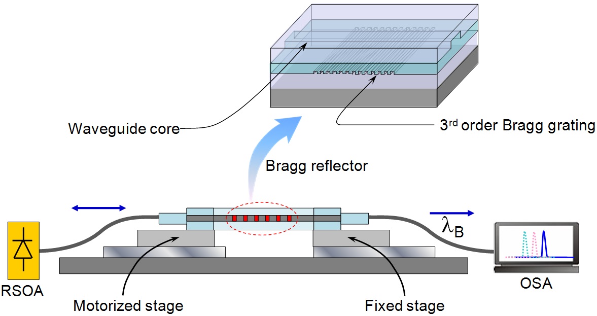
The external-cavity tunable laser, as shown in Fig. 1, consists of a polymer-waveguide Bragg reflector and a semiconductor optical amplifier (SOA) with a high-reflection coating on one side. The Bragg grating is located under the waveguide core layer. To design waveguide structure suitable for the NIR wavelength range, low-loss fluorinated polymer materials obtained from ChemOptics Co. were used, which have the refractive indices of 1.455 and 1.430 for 1550 nm. The refractive index increases to 1.462 and 1.435 for 830 nm. The large refractive index contrast between the two polymers is suitable for increasing the reflectivity of surface relief grating even for shallow grating etch depth.
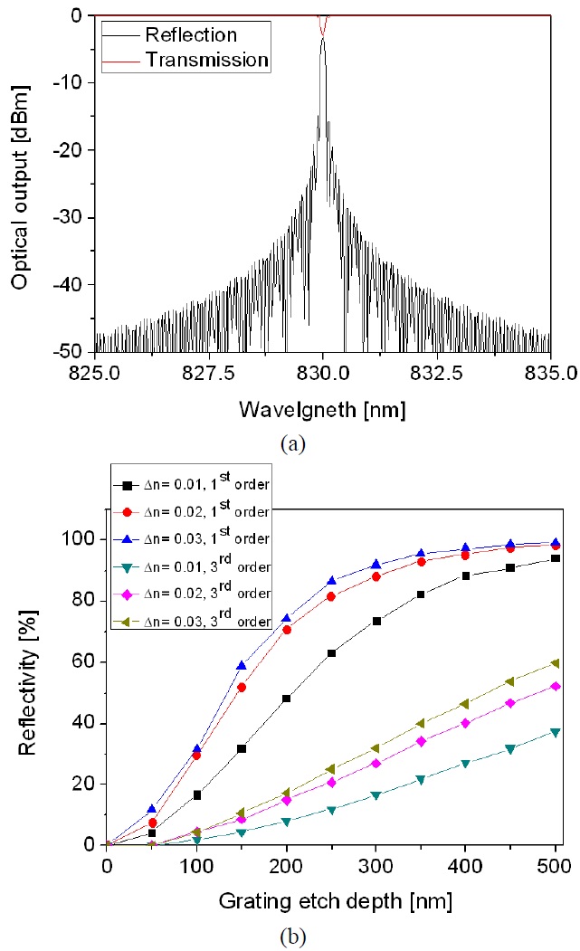
The effect of grating depth on the reflectivity is evaluated as shown in Fig. 2. Considering the refractive index of available polymer material, we carefully design the structure of optical waveguide as well as the Bragg grating structure in terms of the effective index method and the transmission matrix method [13]. In the result given in Fig. 2, the refractive index contrasts of core and cladding materials were chosen to be 0.01, 0.02, and 0.03. Then, for the waveguide core dimension of 4 × 6 μm2, the rib height of waveguide was determined in order to satisfy the single mode condition. The rib height in this case became 1.5 ~ 2.1 μm corresponding toctive index contrast. For the target wavelength of 830 nm and the total length of grating of 3 mm, by using the transmission matrix calculation, a typical reflection and transmission spectra could be found as shown in Fig. 2(a). The reflectivity is dependent on the surface modulation depth of the grating pattern which is determined by the grating etch depth. Therefore, it is necessary to find the reflectivity of the grating as a function of the grating etch depth, which is shown in Fig. 2(b). From this graph, one can find that the reflectivity could be increased over 50% in the 3rd order grating with a length of 3 mm if the refractive index
contrast is higher than 0.02.
Direct fabrication of polymer waveguide devices on top of a flexible polymer substrate is complicated, due to the unstable ground which is easily bent by heating, poor heat transfer through the plastic, and difficulty of spin coating. Hence, we adopted the post lift-off process based on the selective adhesion property of SU-8 material [9]. The post-lift off of the flexible layer, after it is fabricated on a hard silicon substrate, increases the reproducibility of the flexible device fabrication process.
The device was fabricated on a silicon wafer coated with a pattern of Au/Cr layer for the selective lift-off. The flexible substrate consisted of SU-8/NOA61/SU-8 layers with a total thickness of about 100 μm. To provide good flexibility, NOA61 was used to form the thickest layer instead of using the stiff SU-8. Over the flexible substrate,
the waveguide layer was formed by the spin coating and UV-curing of two ZPU polymers (product of ChemOptics Inc.) for the core and claddings. The 3rd order Bragg grating with a period of 873 nm was patterned in the PR layer on top of the lower cladding layer by laser interferometry with a 442-nm He-Cd laser. Then the grating pattern was transferred to ZPU cladding layer by oxygen plasma etching. By over coating the core material, a periodic modulation of the core layer thickness was produced to form the Bragg grating. Details of the fabrication procedures could be found in our previous publication [9,14].
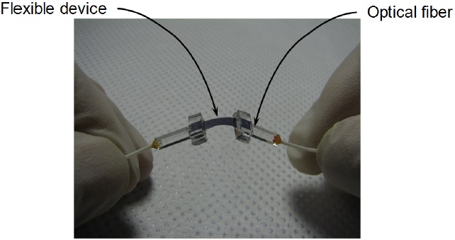
The waveguide rib was defined by dry etching the core layer in an oxygen plasma with a photoresist as the etch mask. The device was made to be flexible through the lift-off of a selected area covered by the Au pattern. Fig. 3 shows the flexible Bragg grating waveguide device with glass blocks attached for the fiber pigtail. Without additional polishing, the single mode fibers inserted in a quartz ferrule were pigtailed. Before the sample was held by the pressure applying fixture, PDMS blocks were attached by sandwiching the flexible part, so as to prevent the bending of the thin film by the compression. The thickness of the PDMS block compared to the length of flexible substrate determines how effectively compress the sample without buckling. The length of the flexible part became 9.4 mm after the glass block was attached, and the thickness of the PDMS sandwiching structure was about 2.5 mm.
III. CHARACTERIZATION OF FLEXIBLE NIR TUNABLE LASERS
The spectral response of the fabricated tunable Bragg reflector device was characterized by using an SOA with a center wavelength of 838.8 nm and a 3-dB bandwidth of 55.7 nm. A high-reflection coating was applied on one side of the SOA, and the other side was subjected to anti-reflective treatment so that the SOA can be used as a gain medium in the external-cavity laser. The propagation loss of the straight waveguide at NIR wavelength was
measured to be 1.2 dB/cm by the cutback method. Fiberto- fiber insertion loss measured from a 1-cm long straight waveguide with a grating was about 3 dB. Due to the stronger scattering for the shorter wavelength, the propagation loss was increased for the NIR wavelength than the results of previous devices operating at 1550 nm wavelength [9].
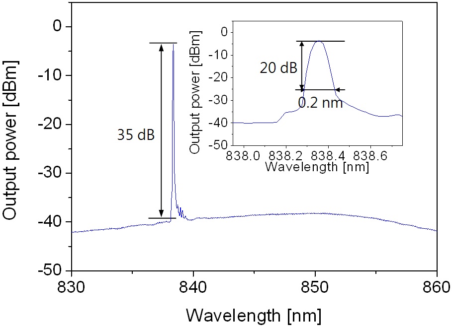
The output spectrum of the external-cavity laser is shown in Fig. 4 along with an inset of 0.05 nm resolution measurement result. The lasing spectrum exhibited a SMSR of 35 dB, a 20-dB bandwidth of 0.2 nm and a 3-dB bandwidth of 0.05 nm, which were limited by the resolution of spectrum analyzer. A fiber-optic polarization controller was inserted to excite TE polarization on the waveguide, and the output power was about -3.0 dBm.
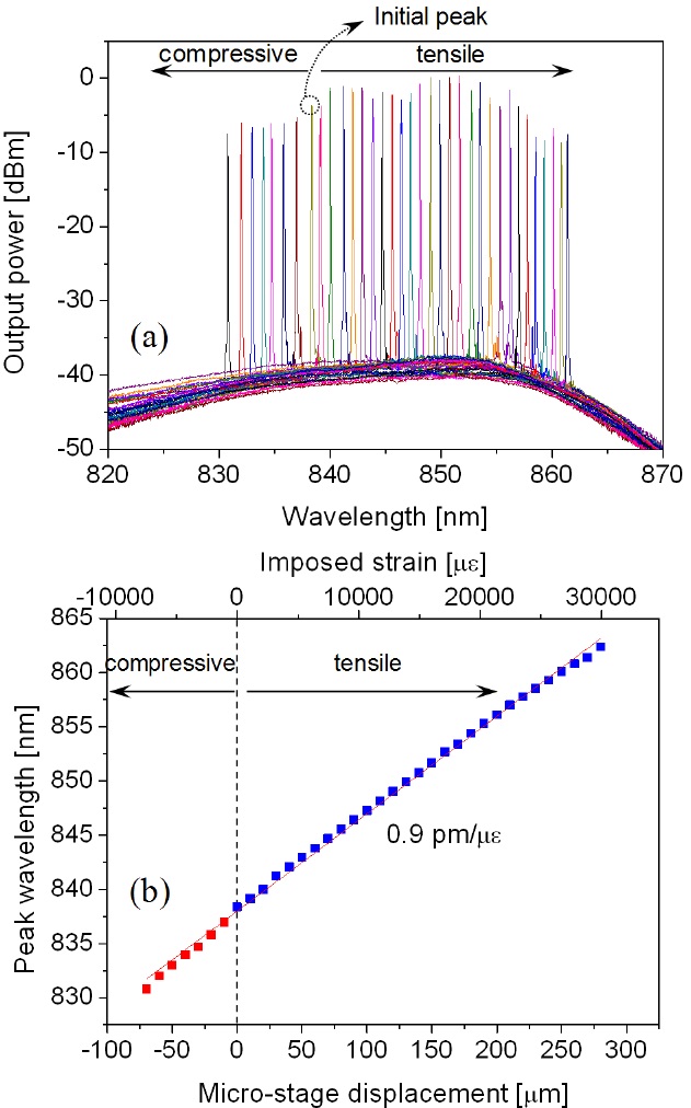
For the wavelength-tuning experiment, the flexible polymer device was attached on a motorized precision stage. Initial lasing peak was located at 838.8 nm. As the stage was moved by 10 μm in each step, the lasing spectrum was shifted as shown in Fig. 5(a). When the stage was moved by 70 μm to impose compressive strain, the peak was shifted by 7.6 nm to the shorter wavelength of 830.7 nm. Then, the stage was moved by 280 μm to stretch the flexible sample and impose tensile strain, and the wavelength peak was shifted by 24.0 nm to the longer wavelength of 862.4 nm. By considering the length of flexible waveguide, the imposed strain was calculated to be 7480 με (0.75%) and 29920 με (2.99%) for the compressive and tensile strains, respectively. During the stepwise movement, there was fluctuation of the output power, which might be caused by the unstable polarization on a single mode fiber between the polymer waveguide and the reflective SOA. The power fluctuation could be reduced by employing a polarization maintaining fiber.
The wavelength peak shift was almost linearly proportional to the imposed strain as shown in Fig. 5(b), and the efficiency of wavelength tuning by the imposed strain
was obtained by the linear fitting of the experimental result as 0.89 pm/με. Compared to the tensile strain, compressive strain was much harder to impose due to the buckling and bending of the flexible device. The buckling problem could be prevented by reducing the length of flexible sample and improving the sample holding method, and then the tuning range could be significantly extended because the imposed strain could be readily increased over 5% in a polymer material.
In conclusion, a flexible tunable laser was demonstrated for NIR wavelength. The 3rd order Bragg reflection grating imbedded in a polymer waveguide was optimized to produce an appropriate reflection spectrum for NIR-ECL with a center wavelength around 840 nm. Compressive and tensile strains were imposed across the flexible polymer device so as to achieve the wavelength tuning of 32 nm. The wavelength peak shift was linearly proportional to the imposed strain, and the wavelength tuning efficiency was 0.9 pm/με. Single mode operation throughout the entire tuning range was observed with a side mode suppression ratio of 35 dB. By modifying the mechanical actuation method, the tuning range of the flexible Bragg reflector could be extended until the tuning range covers the gain spectrum of the SLD, then the tunable laser would find various applications.