검색 전체 메뉴
PDF
맨 위로
OA 학술지
Fabry-Perot Filter Constructed with Anisotropic Space Layer and Isotropic Mirrors
  • 비영리 CC BY-NC
  • 비영리 CC BY-NC
ABSTRACT
Fabry-Perot Filter Constructed with Anisotropic Space Layer and Isotropic Mirrors
KEYWORD
Thin films , Optical properties , Birefringence
  • I. INTRODUCTION

    Sculptured thin film (STF) is a nanostructured solid state film with anisotropic and continuum characteristics that can be deposited via the glancing angle deposition technique (GLAD). Such films show lower density than that of the bulk form, and have several potential applications in catalytic surfaces [1,2], micro-sensor elements [3-5], low dielectric materials [6], etc. The theories of the electromagnetic wave propagation in STF have been well established [7-10]. With the help of state of the art technology, the nanostructure of the GLAD films can be fabricated in different forms, from the simple microstructures, i.e., oblique column, zigzag, helix [11-13], to exotic nanostructures, i.e., polygonal spirals, superhelices, etc. [14,15]. To date, a large number of optical components, such as laser cavity filters [16,17], phase compensators [18], antireflection coatings [19], polarizers [20], etc., have been prepared successfully. The development of STF provides more flexible materials for the design and fabrication of optical devices, especially for the phase and polarization of optical components. In contrast to conventional optical components that are made from isotropic thin films, devices constructed with anisotropic thin films (ATFs) can perform better in manipulating the polarization state of electromagnetic waves because an ATF presents birefringence. This property is very important to the development of polarization and F-P filter components for the miniaturization of integrated optical systems.

    In this study, a new design concept of Fabry-Perot (F-P) filter, constructed with an anisotropic space layer and a couple of isotropic mirrors, with the alternative high and low refractive indices, was proposed. In addition, a software package based on the characteristic matrix method was developed to calculate the optical properties of the anisotropic and isotropic thin films, i.e., transmittance, reflectance, transmission phase, and reflection phase. Single- and doublecavity F-P filters were also designed. Furthermore, the dependence of transmittance and transmission phase on the column direction of the anisotropic space layer and the incidence angle was investigated.

    II. THE SINGLE- AND DOUBLE-CAVITY FABRY-PEROT FILTER DESIGNS

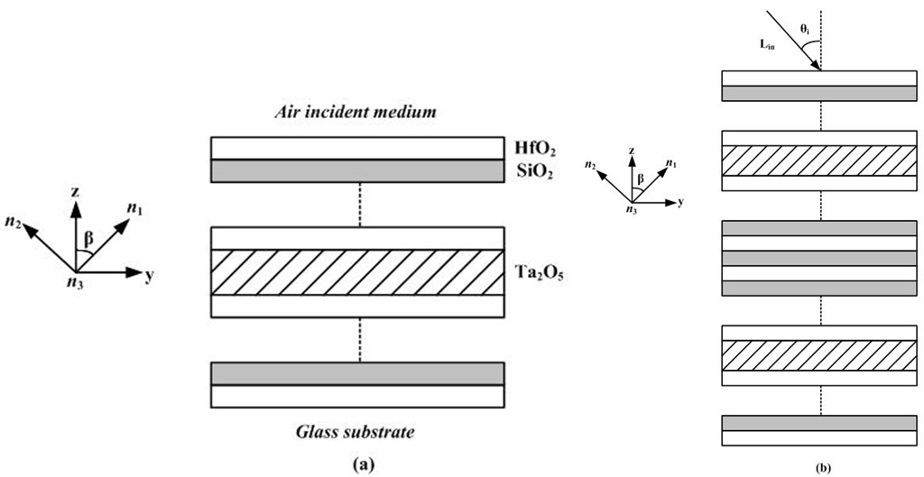
    In our design, the basic type of F-P filter comprises quarter-wave isotropic layers with alternative high and low refractive indices and half-wave anisotropic space layer, denoted as H, L, and 2N, respectively.

       2.1. Single Cavity Fabry-Perot filter

    The structure of the single cavity filter is Glass/(HL)5H 2N (HL)5H/Air. The optical thickness of H, L, and N layers is

    image

    at the reference wavelength λ0 = 632.8 nm. HfO2 with nH =1.913 and SiO2 with nL =1.46 at λ0 were used to construct the high reflectors for the filter. A biaxial anisotropic Ta2O5 thin film, with the principal refractive indices of n1 =1.81, n2 =1.74, and n3 =1.78, and the column angle β =30°, was used as the space layer [21]. The incident and emergent media are homogeneous isotropic air and glass substrate. The schematic of the single- and double-cavity filter is shown in Figs. 1(a) and 1(b). One of the principal axes (labeled 1) of the anisotropic space layer is oriented in the direction of the columns, whereas the other principal axis (labeled 2) is perpendicular to the principal axis 1. The third principal axis (labeled 3) is perpendicular to the plane of incidence.

       2.2. Double Cavity Fabry-Perot filter

    The transmittance curve of the single-cavity filter is nearly triangular, and one half of the energy transmitted lies beyond the pass band. When two or more of the filters are placed in series, a rectangular transmission curve can be obtained. Furthermore, the attenuation outside the pass band is greater than the single filter structure. Similar to the single cavity F-P filter structure, the double-cavity filter is also constructed with isotropic HfO2, SiO2, and anisotropic Ta2O5. The structure of the double-cavity filter is Glass/(HL)5H 2N (HL)5H L (HL)5H 2N (HL)5H/Air.

    III. RESULTS AND DISCUSSION

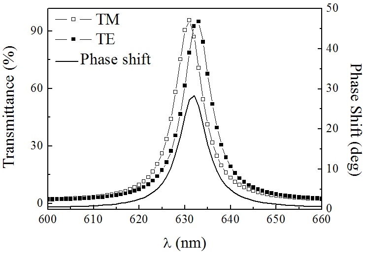
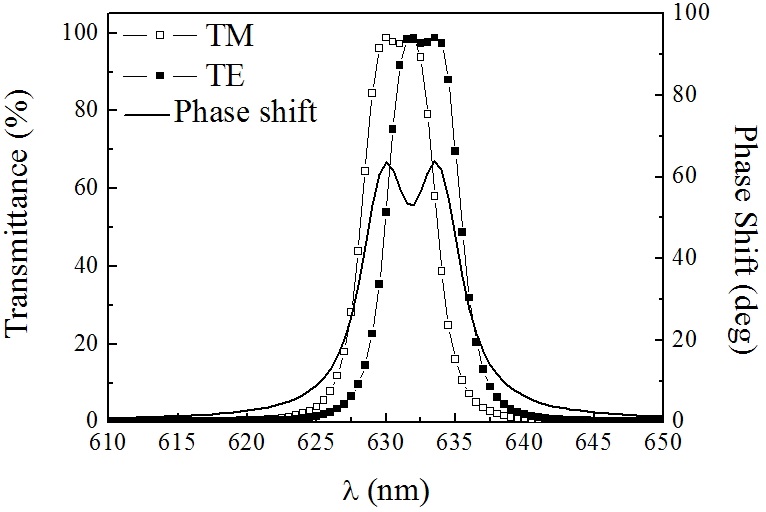
    The transmittance and phase shift of a single cavity filter for the two polarizations at the normal incidence are depicted in Fig. 2. As can be seen, the transmittance spectra are separated for two polarized states, anisotropic space layer yields different phases for the TM and TE waves, and the central wavelength of the filter for the two polarizations are not overlapped at the normal incidence, different from the all-dielectric filter constructed with the isotropic materials. Moreover, the transmittance and transmission phase shift are nearly triangular, and the peak value of the phase shift is about 28.3° at the 632.8 nm wavelength.

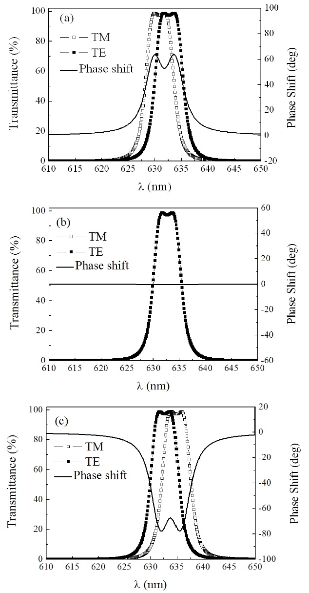
    The transmittance and phase shift of the double-cavity filter are illustrated in Fig. 3. Similarly, the transmittance and transmission phase shifts are nearly rectangular, and exhibit ripples in the transmission band. The phase shift is about 60° near the central wavelength, and is almost doubled compared with that of the single-cavity filter, indicating that the phase shift is almost proportional to the physical thickness of the anisotropic space layer in the filters.

    For the filter in Fig. 1, the TE wave propagates along with an ordinary direction with the index of refraction n3, independent of the propagation direction. By contrast, the TM wave is extraordinary, and the optical properties of the filter are dependent on the column angle β and the

    principal refractive indices n1 and n2. Under the boundary continuity condition of Maxwell’s equations, our previous study [22] has deduced the characteristic matrices for the TE and TM waves and represented them by

    image

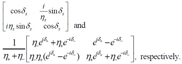
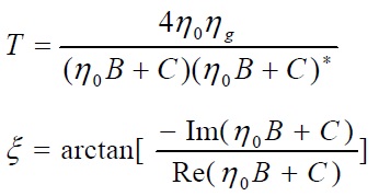
    With the matrix relationship given above and Fresnel’s law, it yields the transmittance T and phase shift on transmission ξ of the assembly [23]:

    image

    The transmittance and phase shift of the double-cavity filter with different column angles are shown in Fig. 4. For the column angle β =90°, the column is parallel to the interface of the thin film, the central wavelength of the filter for the TE wave is longer than that of the TM wave, and the phase shift is about 60° in the pass band. The red-shift of the central wavelength of the TM wave occurs when the column angle decreases; the transmittance of the filter for the two polarizations nearly overlaps at the column angle of 45°. In this case, the phase shift is almost 0° for the pass band and rejection band. When the column angle further decreases, the central wavelength of the TM wave surpasses that of the TE wave, and the negative phase shift occurs in the pass band. The phase shift of -80° is obtained in the pass band of the filter as the column perpendicular to the interface of the thin film.

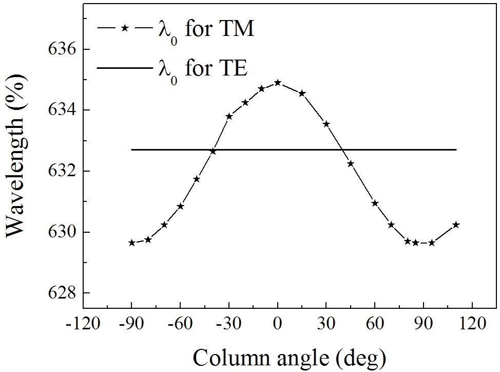
    The dependence of the central wavelength of the doublecavity filter on the column angle is plotted in Fig. 5 for the TE and TM waves. The central wavelength of the TE wave is determined by the refractive index n3, independent on the column angle. However, the optical thickness of the space layer is dependent on the column angle for the TM waves, which yields the variable central wavelength of the filter for different column angles. The maximum and minimum wavelengths are 635 nm and 629.5 nm for the column perpendicular and parallel to the interface of the thin film, respectively.

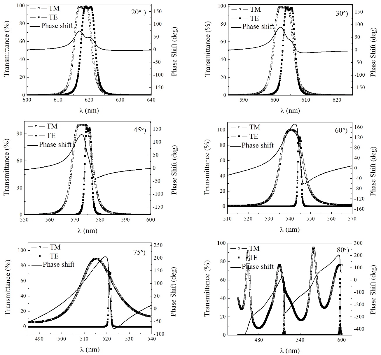
    For the oblique incidence, the tilted optical admittance and equivalent phase thickness were introduced for the calculation of transmittance and transmission phase shift. The tilted optical admittance and equivalent optical thickness of the TM wave depends on the incidence angle. The transmittances and phase shifts of the double-cavity filter

    are plotted in Fig. 6 at the incidence angles of 20°, 30°, 45°, 60°, 75°, and 80°. The bandwidth of the TM wave increases as the incidence angle increases, whereas that of the TE wave decreases. In addition, the obvious modulation of phase shift in the pass band of the filter is observed. With the increase of incidence angle, the modulation depth varies from 73.1°cidence angle of 20° to 280° andcidence angle of 75°. At the incidence angle of 80°, the transmission spectrum of the filter is distorted severely for the TE and TM waves.

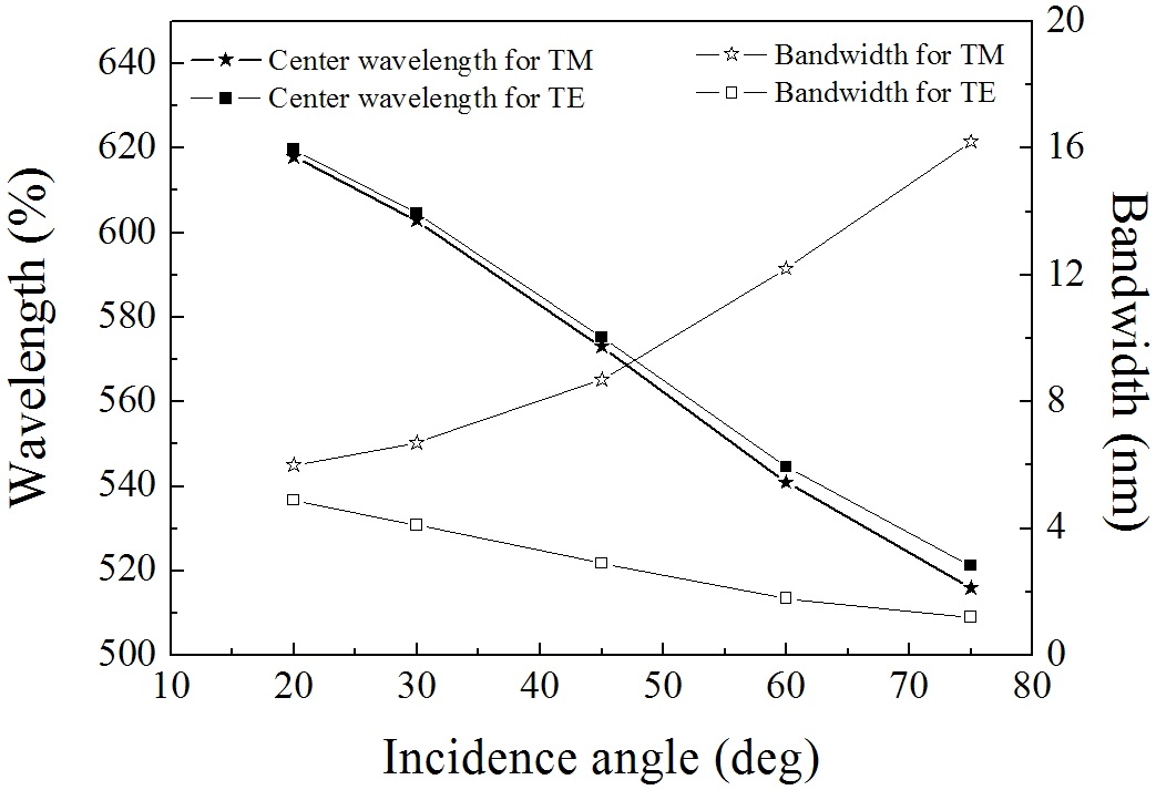
    The dependence of the central wavelength and bandwidth of the double-cavity filter on the incidence angle was also investigated, as shown in Fig. 7. With the increase of incidence angle, the central wavelength decreases from 620 nm to 520 nm for the two polarizations, and the bandwidth increases from 6 nm to 16.2 nm for the TM wave, whereas

    that of TE wave decreased from 4.9 nm to 1.2 nm.

    For the all-dielectric F-P filter designed as (HL)xH 2N (HL)xH, the bandwidth Δ
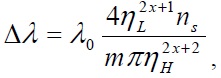
λ is given by:

    image

    where m is the order of filter and ns refers to the refractive index of the incident or emergent medium. At the oblique incidence, the tilted optical admittance η can be written as: ηL = nL / cosθL and ηH = nH / cosθH for the TM polarization and ηL = nL·cosθL and ηH = nH·cosθH for the TE polarization. With the increase of the incidence angle, the ratio of the tilted optical admittances ηL / ηH increases for the TM polarization, resulting in the increase of bandwidth. However, the opposite trend occurs for the TE polarization.

    IV. CONCLUSION

    The single- and double-cavity Fabry-Perot filters, constructed with anisotropic space layer and isotropic mirrors, were designed based on the Maxwell equations and the characteristic matrix method. The dependence of the transmittance and phase shift for two orthogonal polarization states on the column angle of the anisotropic space layer and the incidence angle was discussed. The results show that the anisotropic space layer has an important role for the transmittance and phase shift of the filters. We demonstrated that the polarization state of electromagnetic waves and phase shift can be modulated by using an anisotropic space layer in a polarization F-P filter. Birefringence ascribed to the orientated growth and anisotropic microstructures provided a sophisticated phase modulation with varied incidence angles over a broad range to have a wide-angle phase shift. This new concept would be useful in designing optical components by exploiting the isotropic and anisotropic materials.

참고문헌
  • 1. Gibbs J. G., Zhao Y. P. (2009) “Design and characterization of rotational multicomponent catalytic nanomotors” [SMALL] Vol.5 P.2304-2308 google cross ref
  • 2. Plawsky J. L., Kim J. K., Schubert E. F. (2009) “Engineered nanoporous and nanostructured films” [Materials Today] Vol.12 P.36-45 google cross ref
  • 3. Shalabney A., Khare C., Rauschenbach B., Abdulhalim I. (2011) “Sensitivity of surface plasmon resonance sensors based on metallic columnar thin films in the spectral and angular interrogations” [Sens. Actuators B] Vol.159 P.201-212 google cross ref
  • 4. Liu Y. J., Shi J. J., Zhang F., Liang H. N., Xu J., Lakhtakia A., Fonash S. J., Huang T. J. (2011) “High-speed optical humidity sensors based on chiral sculptured thin films” [Sens. Actuators B] Vol.156 P.593-598 google cross ref
  • 5. Lakhtakia A. (1998) “On determining gas concentrations using thin film helicoidal bianisotropic medium bilayers” [Sens. Actuators B] Vol.52 P.243-250 google cross ref
  • 6. Venugopal V. C., Lakhtakia A., Messier R., Kucera J. (2000) “Low-permittivity nanocomposite materials using sculptured thin film technology” [J. Vac. Sci. Technol. B] Vol.18 P.32-36 google cross ref
  • 7. Holmes D. A., Feucht D. L. (1966) “Electromagnetic wave propagation in briefringent multi-layers” [J. Opt. Soc. Am.] Vol.56 P.1763-1769 google cross ref
  • 8. Schesser J., Eichmann G. (1972) “Propagation of plane waves in biaxially anisotropic layered media” [J. Opt. Soc. Am.] Vol.62 P.782-791 google
  • 9. Berreman D. W. (1972) “Optics in stratified and anisotropic media: 4×4-matrix formulation” [J. Opt. Soc. Am.] Vol.62 P.502-510 google cross ref
  • 10. Cojocaru E. (2000) “Simple recurrence matrix relations for multilayer anisotropic thin films” [Appl. Opt.] Vol.39 P.141-148 google cross ref
  • 11. Robbie K., Brett M. J., Lakhtakia A. (1996) “Chiral sculptured thin films” [Nature] Vol.384 P.616 google cross ref
  • 12. Messier R., Gehrke T., Frankel C., Venugopal V. C., Otano W., Lahktakia A. (1997) “Engineered sculptured nematic thin films” [J. Vac. Sci. Technol. A] Vol.15 P.2148-2152 google cross ref
  • 13. Robbie K., Brett M. J. (1997) “Sculptured thin films and glancing angle deposition: growth mechanics and applications” [J. Vac. Sci. Technol. A] Vol.15 P.1460-1465 google
  • 14. van Popta A. C., Brett M. J., Sit J. C. (2005) “Doublehanded circular Bragg phenomena in polygonal helix thin films” [J. Appl. Phys.] Vol.98 P.083517 google
  • 15. Messier R., Venugopal V. C., Sunal P. D. (2000) “Origin and evolution of sculptured thin films” [J. Vac. Sci. Technol. A] Vol.18 P.1538-1545 google
  • 16. Mentel J., Schmidt E., Mavrudis T. (1992) “Birefringent filter with arbitrary orientation of the optic axis: an analysis of improved accuracy” [Appl. Opt.] Vol.31 P.5022-5029 google cross ref
  • 17. Valle P. J., Moreno F. (1992) “Theoretical study of birefringent filters as intracavity wavelength selectors” [Appl. Opt.] Vol.31 P.528-535 google cross ref
  • 18. YOO J. C., Ping H., Shleh D. (1996) “Fabrication and analyses of negative-birefringent thin film compensator with characteristic matrix” [J. Optics] Vol.27 P.211-215 google cross ref
  • 19. Hodgkinson I. J., Wu Q. H. (1998) “Anisotropic antireflection coatings: design and fabrication” [Opt. Lett.] Vol.23 P.1553-1555 google cross ref
  • 20. Hodgkinson I. J., Wu Q. H. (1999) “Birefringent thin-film polarizers for use at normal incidence and with planar technologies” [Appl. Phys. Lett.] Vol.74 P.1794-1796 google cross ref
  • 21. Qi H. J., Xiao X. D., He H. B., Yi K., Fan Z. X. (2009) “Optical properties and microstructure of Ta2O5 biaxial film” [Appl. Opt.] Vol.48 P.127-133 google cross ref
  • 22. Qi H. J., Zhang D. P., Shao J. D., Fan Z. X. (2005) “Matrix analysis of an anisotropic optical thin film” [Europhys. Lett.] Vol.70 P.257-266 google cross ref
  • 23. Macleod H. A., Pike E. R., Brown G. W. 2010 Thin-film Optical Filters P.13-57 google
OAK XML 통계
이미지 / 테이블
  • [ FIG. 1. ]  Schematic of the single- (a) and double-cavity (b) filter constructed with anisotropic space layer and isotropic mirrors.
    Schematic of the single- (a) and double-cavity (b) filter constructed with anisotropic space layer and isotropic mirrors.
  • [ FIG. 2. ]  Transmittance and phase shift of a single-cavity filter for two polarizations. Design: Glass/(HL) 5H 2N (HL) 5H/Air.
    Transmittance and phase shift of a single-cavity filter for two polarizations. Design: Glass/(HL) 5H 2N (HL) 5H/Air.
  • [ FIG. 3. ]  Transmittance and phase shift of a double-cavity filter for two polarizations. Design: Glass/(HL) 5H 2N (HL) 5H L (HL) 5H 2N (HL) 5H/Air.
    Transmittance and phase shift of a double-cavity filter for two polarizations. Design: Glass/(HL) 5H 2N (HL) 5H L (HL) 5H 2N (HL) 5H/Air.
  • [ FIG. 4. ]  Transmittance and phase shift of the double-cavity filter with the different column angles (a) β = 90 °, (b) β = 45° , and (c) β = 0 °.
    Transmittance and phase shift of the double-cavity filter with the different column angles (a) β = 90 °, (b) β = 45° , and (c) β = 0 °.
  • [ FIG. 5. ]  Dependence of the central wavelength of the doublecavity filter on the column angle.
    Dependence of the central wavelength of the doublecavity filter on the column angle.
  • [ FIG. 6. ]  Transmittances and phase shifts of the double-cavity filter at the incidence angle of 20°, 30°, 45°, 60°, 75° and 80°.
    Transmittances and phase shifts of the double-cavity filter at the incidence angle of 20°, 30°, 45°, 60°, 75° and 80°.
  • [ FIG. 7. ]  Dependence of the central wavelength and bandwidth of the double-cavity filter on the incidence angle.
    Dependence of the central wavelength and bandwidth of the double-cavity filter on the incidence angle.
(우)06579 서울시 서초구 반포대로 201(반포동)
Tel. 02-537-6389 | Fax. 02-590-0571 | 문의 : oak2014@korea.kr
Copyright(c) National Library of Korea. All rights reserved.