Although many researchers have investigated 3D image display and visualization, most of the 3D display technologies are not effective or suitable for commercial applications. This is due to the fact that most of these technologies require supplementary glasses or tracking devices in order to visualize a 3D scene. Some other 3D technologies have been developed, for example stereoscopy [1], autostereoscopy [2], holography [3-4]. Amongst these techniques, integral imaging is an attractive autostereoscopic 3D display technology using a lens array [5-18]. An integral imaging system consists of a pickup and display sections. In the pickup section, an object is imaged through a lens array. Each elemental lens forms a corresponding image of the object, and the elemental images are captured by a charge-coupled device (CCD) camera. However, when we obtain elemental images from real objects in a conventional optical pickup method, there are some disadvantages in using a lens array [5-16]. The setup of a lens array and a CCD camera should be placed exactly, and it should prevent unnecessary beams to come into the lens array. Also, aberrations of the lenses should be considered, generated elemental images sometimes need post-processing, and so on. Furthermore, generating elemental images from an object as big as a person, requires a complex optical structure, because of limitations of the camera lens and lens array.
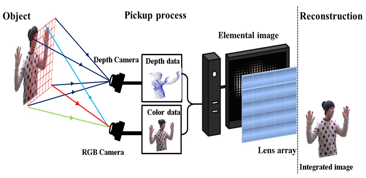
In order to overcome these drawbacks, in this paper, we present a new pickup method to extract 3D information from a real object using a depth camera, then to generate elemental images based on the depth and color data of object pixels. The configuration of the proposed method is shown in Fig. 1. The proposed pickup method just needs a depth camera, PC, and LCD monitor. As shown in Fig. 1, we can generate elemental images from people without a lens array. Hence it has simplified the optical setup of the pickup process, and the problems in conventional pickup process caused by using a lens array have been solved. Finally, a 3D image would then be integrated through a lens array and the image can be observed as being a natural 3D image. The proposed pickup method computes the elemental image pixel coordinates, as if they focused through a lens
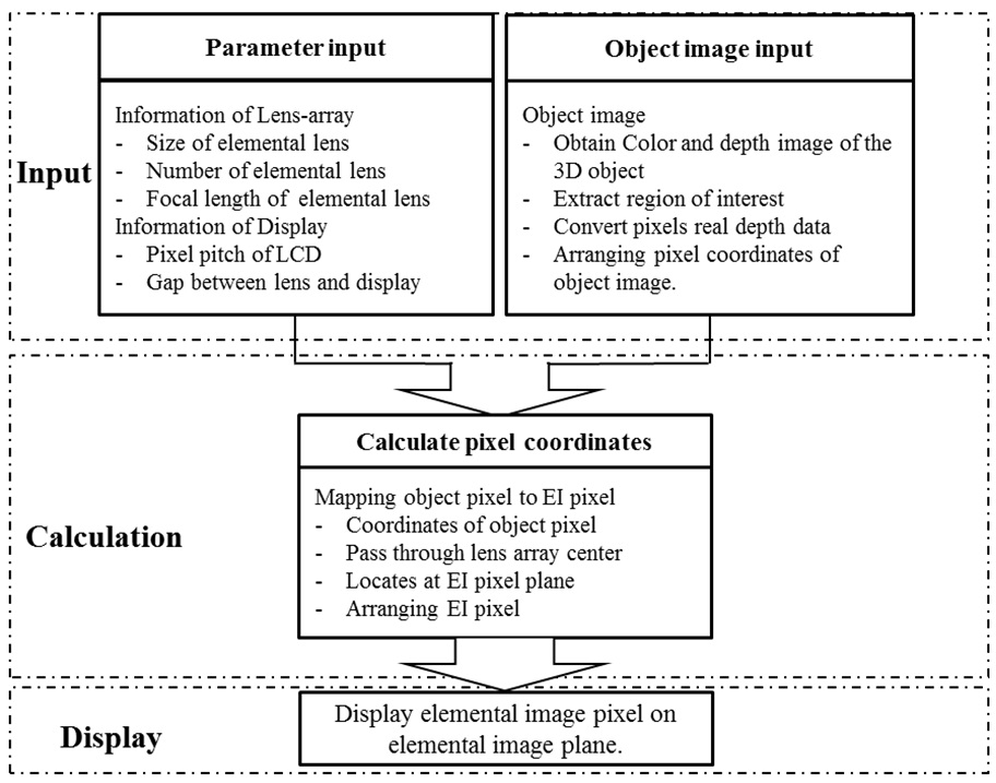
array. The proposed method consists of three stages: input, calculation and display. Fig. 2 shows the architecture of elemental images generation using the proposed method. Object information is entered in the input stage. Then elemental image generation uses pixel mapping based on the object information in the calculation stage. Finally, we generate the elemental image set.
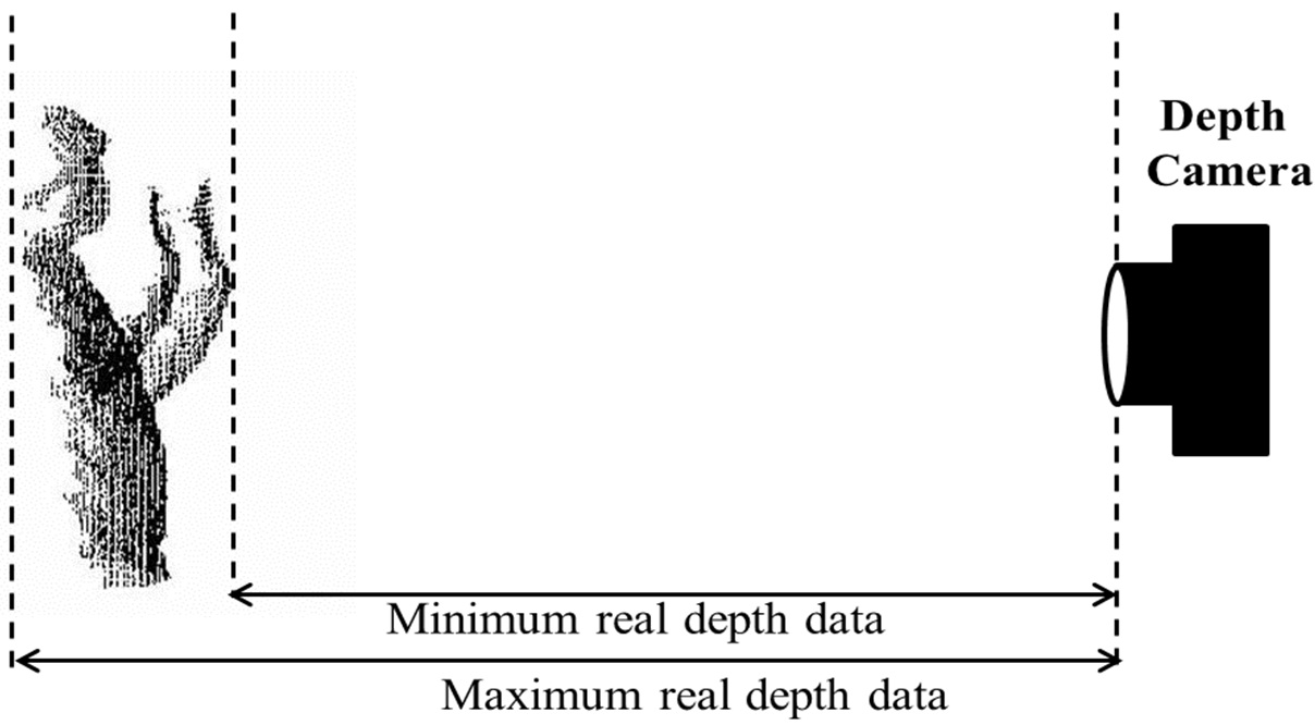
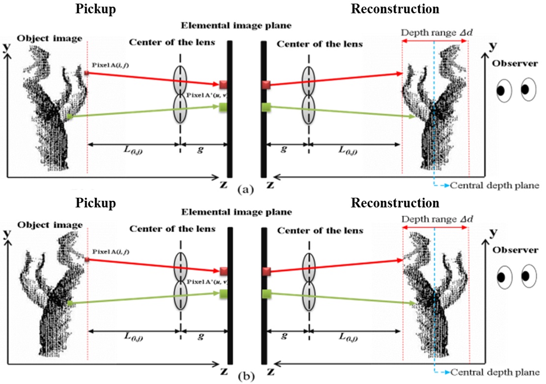
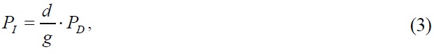
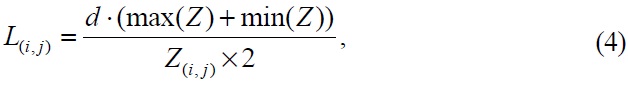
In the input stage, the parameters of the lens array and display panel should be stored in the program. The depth data of every pixel on the 3D object surface has been extracted by the depth camera. An example of extracted depth data distribution is shown in Fig. 3. The depth data of the object are real distance from object surface points to the depth-camera. Note that the obtained object depth information should be converted. There are two reasons why we should convert it. First, when we reconstruct the 3D image depending on our proposed method, it needs to be converted from a pseudoscopic image to orthoscopic image [12,13]. As shown in Fig. 4, if we use the original depth data to reconstruct integral images directly, the recorded elemental images are back-projected through a lens array. As shown in Fig. 4(a), the observed image is reversed.
However our ultimate goal is to display the 3D image as shown in Fig. 4(b). Therefore, the real depth data
where
where
where
III. ELEMENTAL IMAGES CALCULATION AND GENERATION
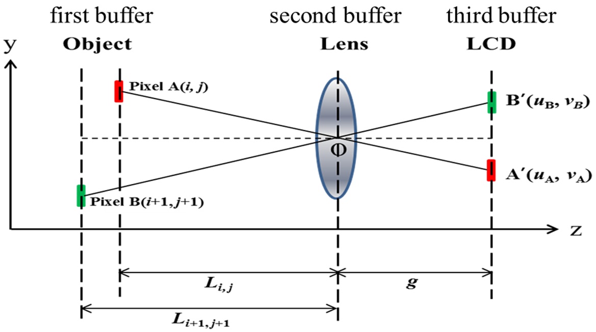
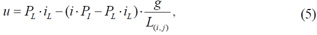
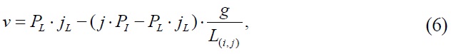
For the calculation stage, we need to create three buffers. The information for every object pixel is stored in the first buffer. The second buffer is reserved for the center coordinates of the elemental lenses. And the third buffer is used for storing the calculated elemental image pixel set. Fig. 5 shows the geometry of pixel mapping from object pixels to the elemental image plane through an elemental lens. The coordinates of the elemental lenses center are computed based on lens pitch and elemental lens indices. As shown in Fig. 5, after the ray of the object pixel
where
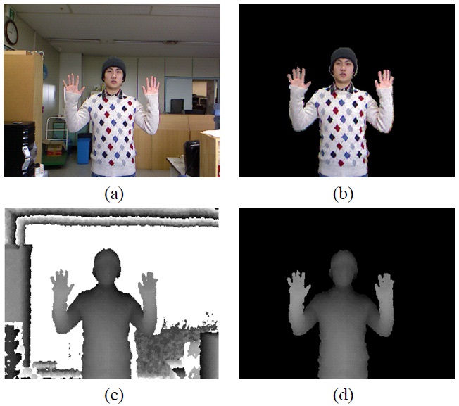
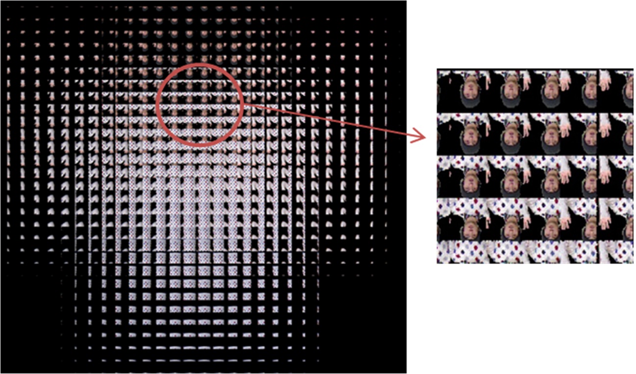
Figure 6 shows the color images of the object and their corresponding depth map. In order to extract the region of interest in the depth map, we separated the background from the person, as shown in Figs. 6(b) and (d). It is necessary to prevent unwanted beams to come into the lens array, in the conventional optical pickup process. While we capture object and separate the background from the object to extract the region of interest, then generate elemental images. So it eased the setup conditions, and it avoided the aberrations caused by lens array, which means we can generate an elemental image from an object almost anywhere. Fig. 7 elemental images plotted by the proposed method.
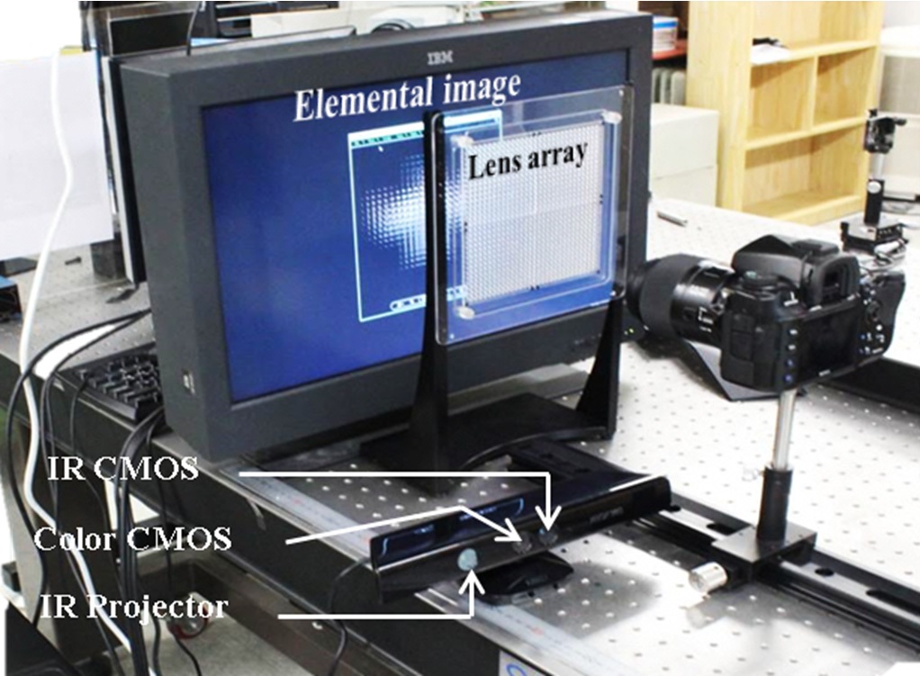
To demonstrate the proposed method, we have carried out an experiment. The implemented experimental setup is shown in Fig. 8. It is composed of a depth camera, a PC, and a high resolution LCD monitor. And the lens array is used in the reconstruction process to integrate elemental image generated by the proposed pickup method. Compared with the conventional optical pickup method, it has significantly simplified the pickup process.
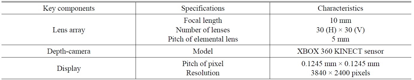
System parameters are listed in Table 1. In our experiment, we used a KINECT sensor as the depth camera. Recently Microsoft released a non-commercial KINECT software development kit (SDK) for Window 7. We use C# program to run the KINECT SDK, and extract each pixel’s real depth data. The depth map resolution is same with the color image, which is 320 × 240. The detectable depth range of the KINECT sensor is from 800 mm to 4000 mm. The extracted real depth range from the object which shown in Fig. 3 is from 994.9 mm to 1207.7 mm, and the real depth data of every pixel is converted by Eq. (4). The lens array used in the experiment consisted of 30(H) × 30(V) rectangular elemental lenses that are 5 mm × 5 mm with a 10 mm focal length. Furthermore the gap between the lens array and the LCD monitor is set to 11mm. In order to verify that the image generated by the proposed pickup method is also effective as a conventional optical pickup method, we captured the reconstruction image obtained by
[TABLE 1.] Specifications of experimental setup

Specifications of experimental setup
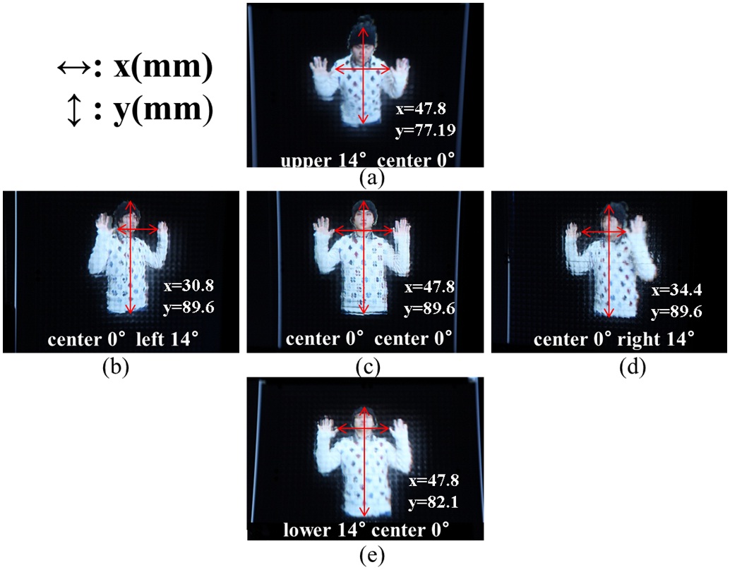
the proposed method in five different viewing positions. Fig. 9 shows the experimental result. As shown in Figs. 9(a), (c), and (e), the vertical distance y between marked pixels are 77.19 mm, 89.6 mm, and 82.1 mm, respectively. It can be confirmed that the proposed method successfully creates pixels disparity in the vertical direction. In the same way, the horizontal distance x between the marked pixels in Figs. 9(b), (c), and (d) is 30.8 mm, 47.8 mm, and 34.4 mm, respectively. It can be also confirmed that the proposed method successfully creates pixels disparity in the horizontal direction. From the experimental result, in different viewing positions we can observe the correct parallax image.
In conclusion, a novel pickup method that generates elemental images from real objects based on integral imaging is proposed. The proposed method extracts 3D information from the object using a depth camera. Since our proposed pickup method generates elemental images without a lens array, the optical pickup process of conventional integral imaging has been simplified. Some disadvantages caused by using a lens array have been solved. If the calculation speed improved, the proposed method can be applied to a
real-time integral imaging display [19], because of the simplified pickup process. Furthermore, it easy to obtain elemental images even from moving objects.