Optical systems have fast parallel information processing and rapid transmission of data. Therefore, optical methods have shown great potential in the field of security applications due to these advantages. Recently, various kinds of optical information processing methods have been investigated for cryptography and security systems. [1-14] In implementing an optical encryption system, the phase has been the most widely used function. However, because a photosensitive device like a charge-coupled device (CCD) cannot record the phase information directly, some innovative techniques to obtain the phase information have been studied in recent decades. Among recent methods the phaseshifting digital holographic technique that uses the CCD camera for direct recording of a hologram has an advantage of real time digital information processing, and it is possible to obtain the full complex phase information. [15-18] Especially the 2-step phase-shifting interferometric technique is applied to cryptography. [19-24] In the previous papers [20,21,24], we proposed an optical encryption system using 2-step phase-shifting digital holography. In the proposed optical system, a PZT driven mirror was used to get a quadrature phase shift of π/2 in the reference beam path of the Mach-Zehnder interferometer. Generally in the phase-shifting interferometric method, a phase shift is acquired by moving the PZT mirror generating an optical path difference in the reference beam path of the interferometer, and the accurate amount of phase shift is implemented by applying the proper voltage to the PZT element, which is attached to the mirror. However, this method has to control the accurate expansion or contraction of the PZT device in order to get the exact phase shift and this makes it difficult to get the accurate phase step in the phase-shifting interferometry due to this electrical and mechanical operation, and therefore phase shift error can occur.
In this paper, a new 2-step quadrature phase-shifting digital holographic optical encryption method using orthogonal polarization is proposed, and the performance of the decryption for cryptography is evaluated. Tolerance errors for the proposed method are also analyzed. Unlike the conventional technique using the PZT mirror, the proposed optical setup employs simply two polarizers and one phase retarder to get the quadrature phase-shifting. A quarter-wave plate(λ /4-plate) is used as a phase retarder, which generates p-polarization interference without phase shift along the vertical direction and s-polarization interference with phase shift of π/2 along the horizontal direction. These two interference patterns correspond to the two intensities resulting from the 2-step quadrature phase-shifting digital holography. An input polarizer makes collimated light into a linear polarized wave. Another output polarizer, called the analyzer, performs separate recording on the CCD according to the polarization direction. Binary image or random generated binary bit data are used as input data to be encrypted, and a random generated binary bit code is used as a security key code for encryption and decryption. The encrypted Fourier transform hologram is obtained by use of a random phase mask pattern attached to a spatial light modulator (SLM), and a 256 gray-level quantized digital hologram is obtained by the CCD. In Section Ⅱ, the principle to acquire the π/2 phase shift using orthogonal polarization and the encryption and decryption process with the 2-step phase-shifting digital holography are described. In Section Ⅲ, computer experiments show results of the decryption with the proposed method and the graph to analyze errors from
misalignment of optical components. Finally, brief conclusions are summarized in Section Ⅳ.
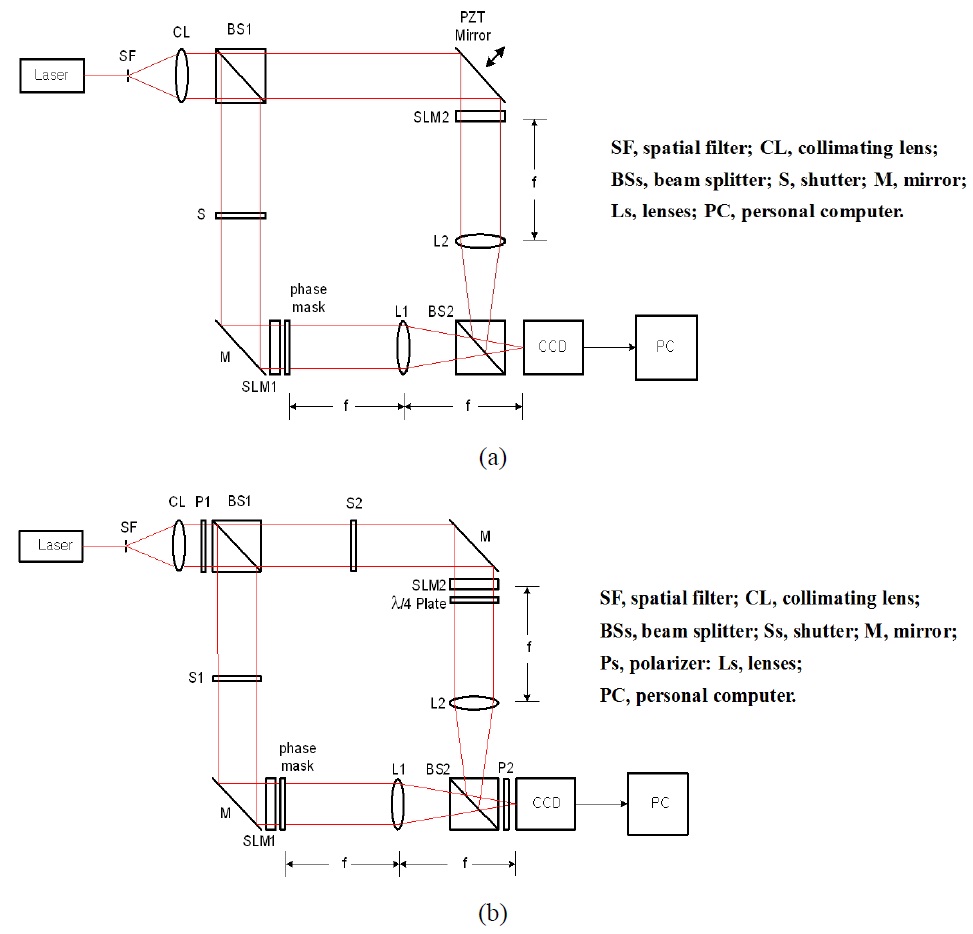
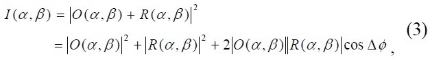
Figure 1(a) shows the conventional schematic optical setup for the 2-step phase-shifting digital holographic optical encryption system by using the PZT mirror, while Fig. 1(b) is the proposed schematic setup for the same 2-step phase-shifting digital holographic optical encryption system by using orthogonal polarization. Schematically, the optical setup contains a Mach-Zehnder type interferometer. Laser light is collimated by a spatial filter (SF) and a collimating lens (CL), and then passes through a linear polarizer (P1) whose polarization direction is 45° with respect to the horizontal axis. A beam splitter (BS1) divides the collimated light into two linearly polarized plane waves as the reference and the object beams. In the reference beam, the 45° linearly polarized light passes through a λ/4-plate which sets the fast-axis along the vertical axis. Then, after passing through the λ/4-plate, quadrature phase shift of π /2 occurs only on the horizontal axis. If we align an output analyzer (P2) whose polarization direction is set on the horizontal axis, a π/2 phase shifted reference beam is obtained on the horizontal axis. On the other hand, when we align the output analyzer (P2) whose polarization direction is set on the vertical axis, no phase shift occurs in the reference beam on the vertical axis. This scheme makes it possible to acquire 2-step quadrature phase-shifting digital holograms with π/2 phase shift between s-polarization and p-polarization on the CCD. Binary image or bit data to be encrypted is displayed on a SLM1 which is attached to a random phase mask, and is Fourier transformed on the CCD by a lens (L1) as the object beam, while a phase-type SLM2 which display a security key code is Fourier transformed on the CCD by a lens (L2) as the reference beam.
The encryption and decryption principle by using the 2-step phase-shifting digital holographic method is described as follows. [24] Let |

Let |

Fourier transformed functions of the binary data and the security key code are supposed to be
where
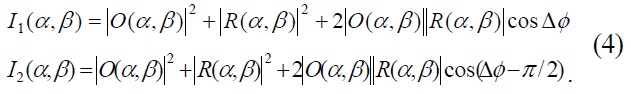
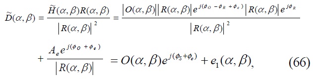
These two digital holograms are encrypted data. After a DC-term removal technique is applied, Eq. (4) is modified as
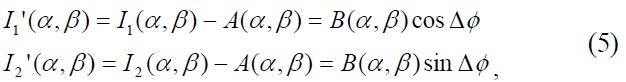
where
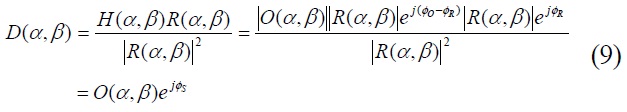
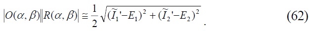
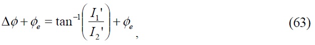
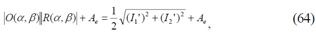
Then, the phase difference of the object beam and the reference beam and the magnitude are calculated as follows.
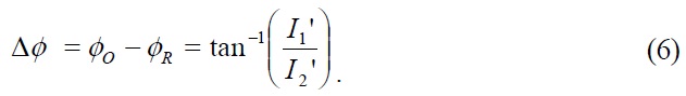

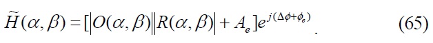
From Eqs. (6) and (7), the complex hologram with encryption information is expressed as

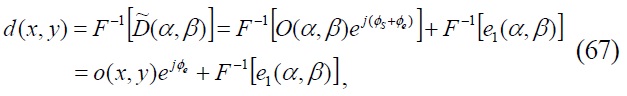
By using this complex hologram and the security key, the reconstructed complex distribution and the original binary data is decrypted.

The proposed architecture comprises optical components such as a polarizer and a phase retarder. In order to acquire exactly a 2-step quadrature phase-shifting interference pattern with π/2 phase shift between s-polarization and p-polarization on the CCD, these optical components must be aligned in the right position without any angular error. For the proposed setup, the polarization direction of the input linear polarizer (P1) is set 45° rotated with respect to the horizontal axis and the fast-axis of the λ/4-plate is aligned along the vertical axis. Also, the polarization direction of the output linear polarizer (P2) is aligned along the vertical axis for the case of recording p-polarization interference and the polarization direction of P2 is aligned along the horizontal axis for the case of recording s-polarization interference. However, a small angular variation of these optical components can cause interference intensity variation error on the CCD.
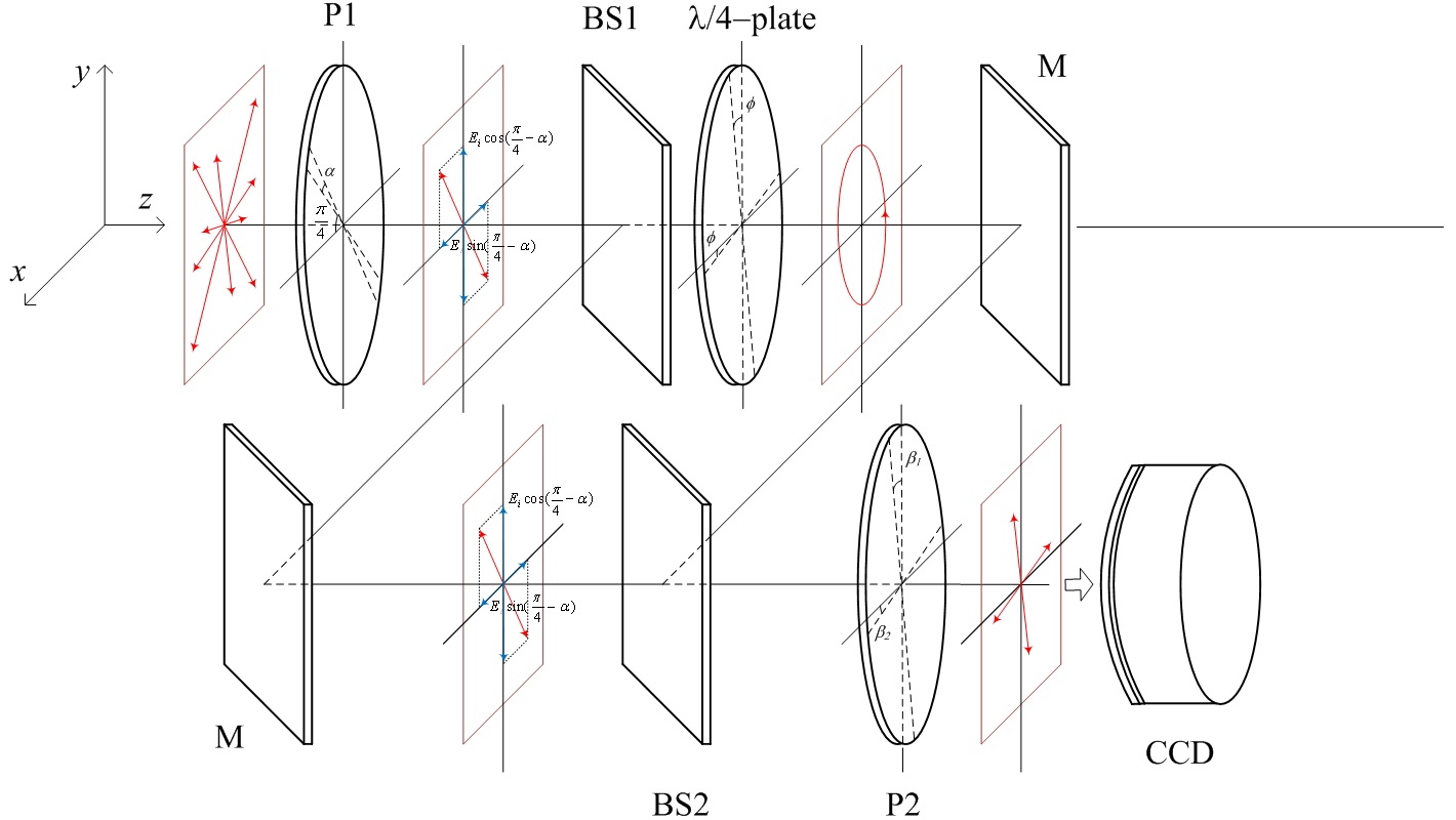
Figure 2 shows schematic drawing of the proposed optical setup for error analysis of the polarization misalignment. The collimated laser light shown in Fig. 1 is expressed as a monochromatic plane wave of angular velocity

The electric field lies in the xy-plane and is generally described by

where

and
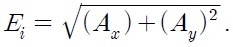
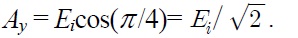
In Fig. 2, when the polarization direction of the input polarizer(P1) is set 45° with respect to the horizontal axis, then each magnitude in the x and y direction is
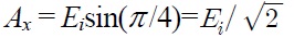
and
Meanwhile, if the polarizer P1 is misaligned with angle error
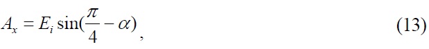

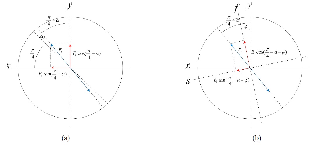
Figure 3(a) shows a coordinate system representation of the xy-axis linear polarization components due to the misalignment of the input polarizer(P1) with
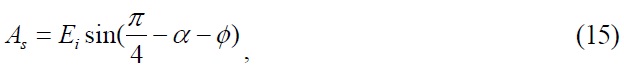
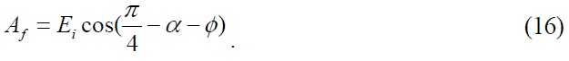
The second error occurs when we misalign the λ/4-plate in the reference path. Considering the case where the fast-axis of the λ/4-plate is misaligned with angle error
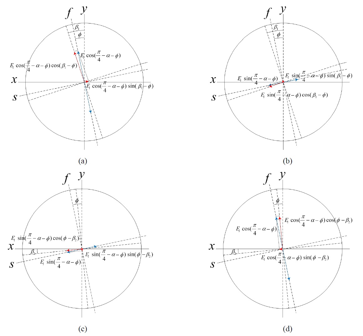
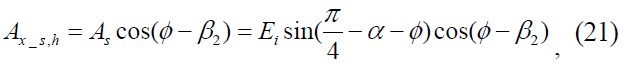
The third error occurs due to the misalignment of the output linear polarizer(P2). When we intend to acquire
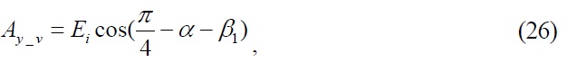
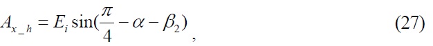
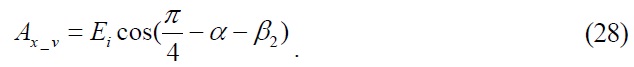
p-polarization interference intensity on the CCD, the polarization direction of the polarizer P2 must be aligned along the vertical axis. On the other hand, when we intend to get s-polarization interference intensity on the CCD, the polarization direction of P2 must be aligned along the horizontal axis. However, a small angular misalignment of this optical component can cause interference intensity variation error on the CCD. Fig. 4 shows a coordinate system representation of the orthogonal linear polarization components considering the misalignment in the reference path. If the polarizer P2 is misaligned with angle error


and


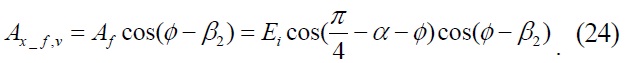
Another error occurs when we consider the same misalignment of the output polarizer(P2) in the object path as in the reference path. Fig. 5 shows a coordinate system representation of the orthogonal linear polarization components
considering the misalignment in the object path. If the polarizer P2 is misaligned with the same angle errors

In this paper, a digital hologram recorded on the CCD results from interference pattern of two Fourier transformed functions. According to a linear property of the Fourier transform theorem, the transform of a weighted sum of two functions is simply the identically weighted sum of their individual transforms. If
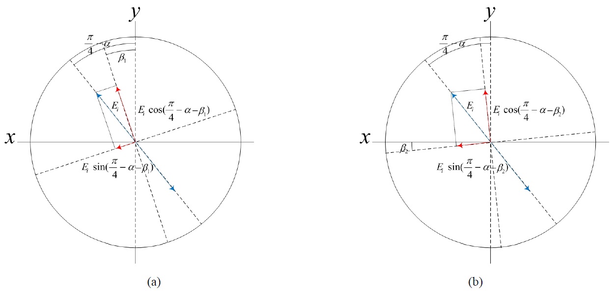
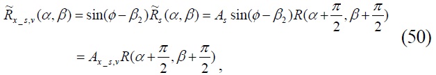
First, we consider the object path. If an object function is represented as Eq. (1) and a monochromatic plane wave is expressed as Eq. (11) and (12), a light function after passing through the object function is defined by

When the misalignment error of the λ/4-plate is
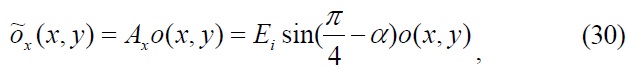
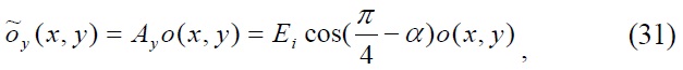
where
If the output polarizer(P2) is misaligned with angle error


where


Second, we consider the reference path. If a reference function is represented as Eq. (2) and a monochromatic plane wave is expressed as Eq. (11) and (12), a light function after passing through the reference function is defined by

When the misalignment error of the input polarizer(P1) is

where


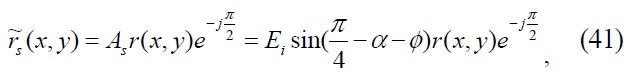
Just like the object path case, if the output polarizer(P2) is misaligned with angle error
and
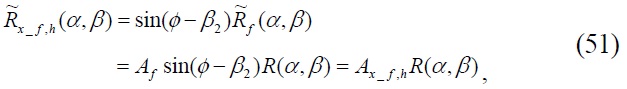
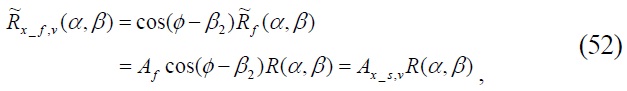
where
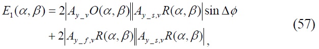
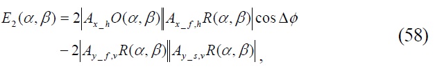
Now, considering these misalignment factors in Eq. (3) and (4), the 2-step quadrature phase-shifting digital holographic intensity pattern recorded by the CCD can be expressed as


where
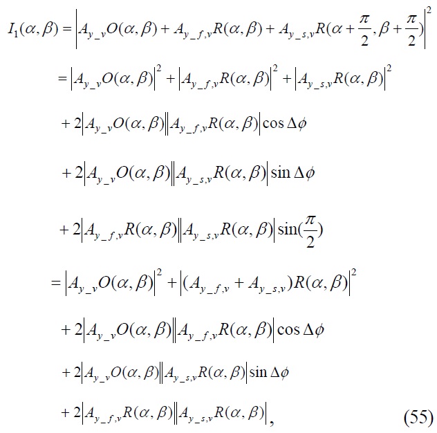
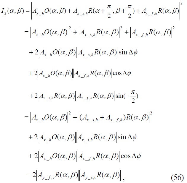
where
With Eqs. (55) and (56), if we let error terms like as
and apply DC-term removal technique, Eqs. (55) and (56) is expressed as


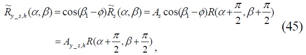
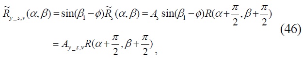
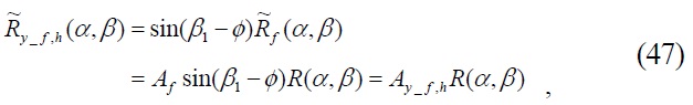
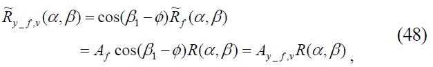
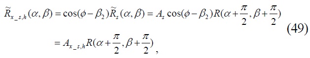
From Eqs. (20), (21), (26) and (27), |
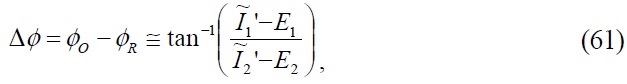
However, because we cannot exclude the error terms
where
By using this complex hologram and the security key, the reconstructed complex distribution and the decrypted binary data are obtained by

where
If there are no misalignment errors of the optical components, i.e.
In the proposed system the number of error pixels between the original data and the decrypted data is defined as

where
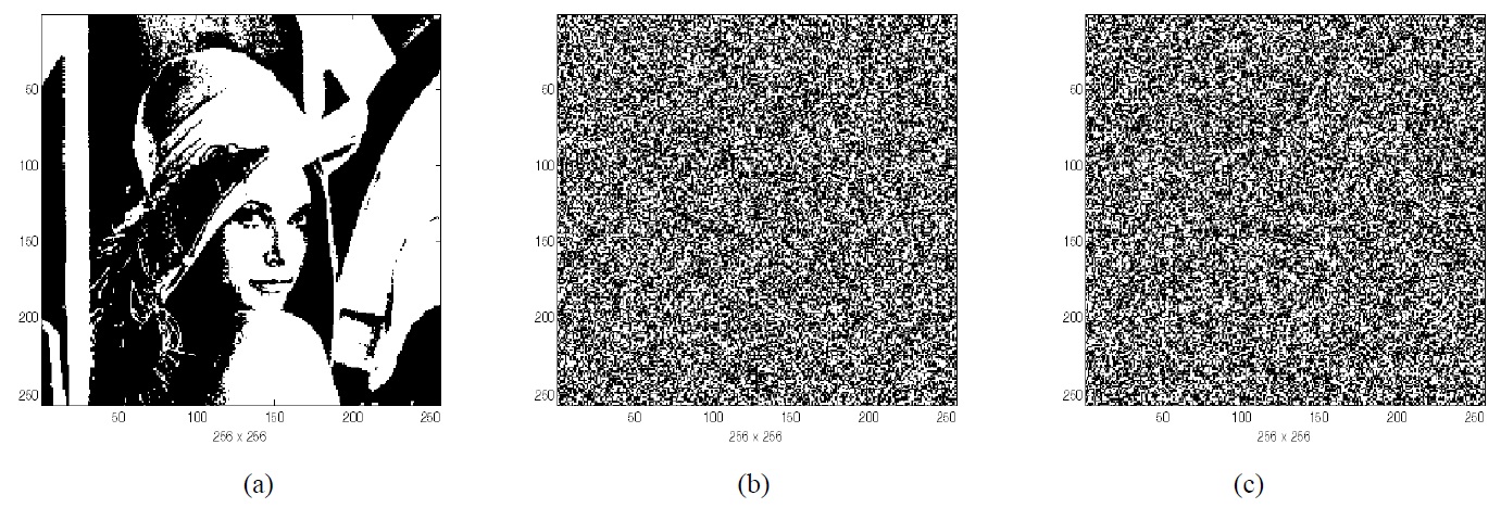
Computer simulations show the decryption performance and error analysis of the proposed 2-step quadrature phaseshifting digital holographic optical encryption method using orthogonal polarization. Binary image and random generated binary bit data of size 256×256 pixels shown in Figs. 6(a) and (b) are used as input data to be encrypted, and Fig. 6(c) shows a random generated binary bit code as a security key code for encryption and decryption.
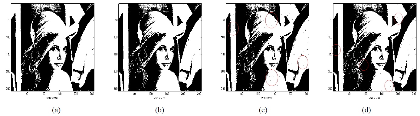
Figure 7 shows an example of the decrypted binary image data for the misalignment of optical components. Fig. 7(a) is the decrypted binary image when the misalignment error of the input polarizer(P1) is 5 degrees. In this case, the reconstructed image is the same as the original image and is not affected by the small misalignment of the input polarizer. Fig. 7(b) is the decrypted binary image when the misalignment error of the λ/4-plate is 5 degrees. Similarly, the reconstructed image is the same as the original image and is not affected by the small misalignment of the λ/4-plate. Figs. 7(c) and (d) are the decrypted binary images when the misalignment error of the output polarizer(P2) is
5 degrees on both the vertical and horizontal axes. However, in this case, the reconstructed image is affected by even the 5 degrees misalignment of the output polarizer and gets damaged in several regions. For some example regions, circular areas shown in Figs. 7(c) and (d) include such an error in the decrypted image. In these circular areas, some dark pixels instead of the correct white pixels and some white pixels instead of the correct dark pixels compared to the reconstructed original image shown in Figs. 7(a) and (b) represent error pixels.
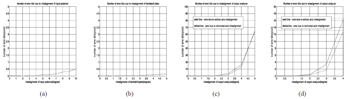
In order to know how many pixels are damaged in the decrypted data, the mismatching error to the original data is investigated and analyzed according to the misalignment of optical components. The random generated binary bit data shown in Fig. 6(b) is used as input data to be encrypted for convenience. All graphs shown in Fig. 8 are an average value obtained by 100 times evaluations to the random generated binary data(256×256 pixels). Fig. 8(a) is the error graph when the misalignment error of the input polarizer(P1) is from 0 to 10 degrees, where the number of error pixels is less than 1 pixel. This means that the small misalignment of the input polarizer(P1) does not affect the decryption data. Fig. 8(b) is the error graph when the misalignment error of the λ/4-plate is from 0 to 5 degrees, where the number of error pixels is also less than 1 pixel. This means that the small misalignment of the λ/4-plate does not affect the decryption data seriously. Fig. 8(c) is the error graph when the misalignment error of the output polarizer(P2) is from 0 to 5 degrees, where the number of error pixels is about 70 pixels for the case of 5 degrees misalignment and is above 2 pixels even if the case of 3 degrees misalignment. Fig. 8(d) shows the magnified graph of the result. This means that the small misalignment of the output polarizer(P2) does affect mainly the decryption data error in the proposed setup. However, the number of error pixels is less than 1 pixel if we control the misalignment error of the polarizer P2 less than 2 degrees. The alignment of the optical components within this angle can be achieved in the setup.
In this paper, a new 2-step quadrature phase-shifting digital holographic optical encryption method using orthogonal polarization is proposed. The π/2 phase shift of the 2-step quadrature phase-shifting digital holography is achieved by constructing a Mach-Zehnder interferometer with two polarizers and one λ/4-plate retarder in the proposed optical setup. This scheme provides a good decryption performance which achieves the same result as the conventional phase-shifting method using the PZT mirror, and has advantages of compactness and easy configuration of the optical system. The error analysis of the proposed method shows that even small misalignment of the output polarizer is the main error source in this system, meanwhile small misalignments of the input polarizer and λ/4-plate do not affect the decryption performance. However, the maximum tolerance error of the output polarizer is about 2 degrees and this amount is acceptable and controllable in the optical setup. Computer experiments verified that the proposed method is a good alternate for cryptography for security applications.