검색 전체 메뉴
PDF
맨 위로
OA 학술지
A Low-cost Optimization Design for Minimizing Chromatic Aberration by Doublet Prisms
  • 비영리 CC BY-NC
  • 비영리 CC BY-NC
ABSTRACT
A Low-cost Optimization Design for Minimizing Chromatic Aberration by Doublet Prisms
KEYWORD
Doublet prisms , Optimization , Chromatic aberration , Ray tracing
  • I. INTRODUCTION

    The image quality of a lens design can be good but the cost of the glass from which it is made can be quite high. Kidger [1] considered variation in cost between glasses used for this purpose. In the large size lenses, the cost of expensive glass could be prohibitive; but in small size lenses, the materials make up only a small percentage of the total cost of the lens, so expensive materials might well be acceptable in this case. Chromatic aberration occurs because of the different refractive indices of lenses for different wavelengths of light [2,3]. If two different types of glasses are combined into a thin two-element system, a paraxial chromatic aberration will develop [4]. Robb [5] developed a method using two different types of glass for the correction of axial color for at least three wavelengths. Certain combinations might be found for correction at four and five wavelengths. In 1983, Sharma and Gopal [6] used the double-graph technique to produce doublet designs. Then, in 2001, Rayces and Rosete-Aguilar [7,8] described a method to select pairs of glasses for both thin cemented achromatic doublets and thin aplanatic achromatic doublets with a reduced secondary spectrum. In another study, Banerjee and Hazra [9] used a genetic algorithm for the structural design of cemented doublets. The aim of this work is to minimize chromatic aberration by using a low-cost optimal double-prism method. An efficient approach for finding an optimum design is also proposed.

    II. METHODS

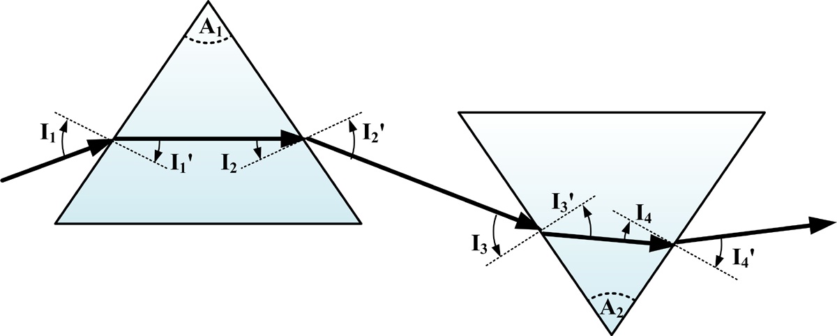
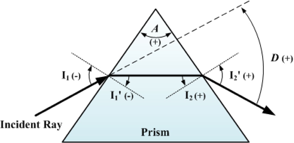
    An illustration of ray tracing in and out of a prism is shown in Fig. 1. The angle of a ray in the normal direction from the prism surface is positive in the anticlockwise

    direction, and negative in the clockwise direction. In this figure, I1 and I2 are the incident angles of the first and the second surfaces, respectively; I1' and I2' are the refractive angles of the first and the second surfaces, respectively; A is the apex angle of the prism. The sign of the apex angle is positive in the vertical, and negative in the inverse direction. The ray thus deviates through an angle of (I1'I1) at the first surface. At the second surface, the ray deviates by (I2'-I2), so the angle of deviation D of the ray is given by

    image

    If we consider real ray tracing, the deviation angle [10] presented by

    image

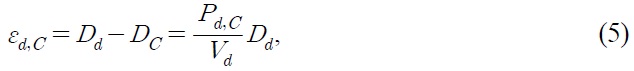
       2.1. Single Prism Paraxial Chromatic Aberration

    If all the angles of the design are small, the equations for the paraxial ray tracing can be obtained, and the paraxial deviation angle [11] given by

    image

    The paraxial primary color εF,C is the difference in deviation angles between F line (0.48613 μm) and C line (0.65627 μm) as shown. Thus

    image

    where Dd is the paraxial deviation angle of d line (0.58756 μm); Vd=(nd - 1)/(nF - nC) is the Abbe number; and nC, nd, nF are the refractive indices of C, d, and F lines, respectively. Consequently, the paraxial second spectrum εd,C is the difference in the deviation angles between d line and C line. This can show as

    image

    where Pd,c=(nd-nC)/(nF-nC) is the relative partial dispersion.

       2.2. Doublet Prisms Paraxial Chromatic Aberration

    In the paraxial ray tracing of doublet prisms, the angle of deviation of d-line light is defined as 3°, so the primary color εF,C is zero [4,5]. These equations can be written as

    image
    image

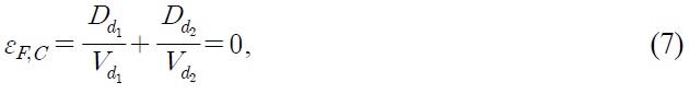
    where the paraxial deviation angles of the doublet prisms are Dd1 and Dd2, respectively. The primary chromatic aberration is εF,C. Solving for Dd1 and Dd2 from the above equations, we obtain

    image

    and

    image

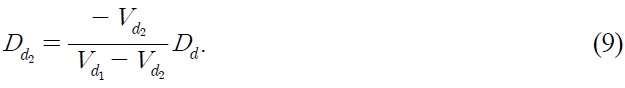
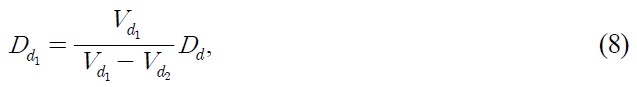
    The apex angles of the doublet prisms are expressed as

    image

    and

    image

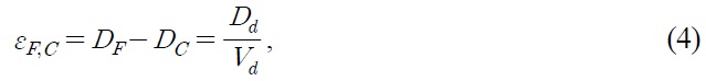
    Accordingly the paraxial primary color is zero, but there are still some paraxial secondary spectra. Thus the paraxial secondary spectrum can be defined as

    image

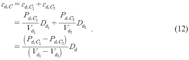
    where the paraxial primary chromatic aberrations of the doublet prisms are εF,C1 and εF,C2, respectively.

       2.3. Schott Glasses Selection

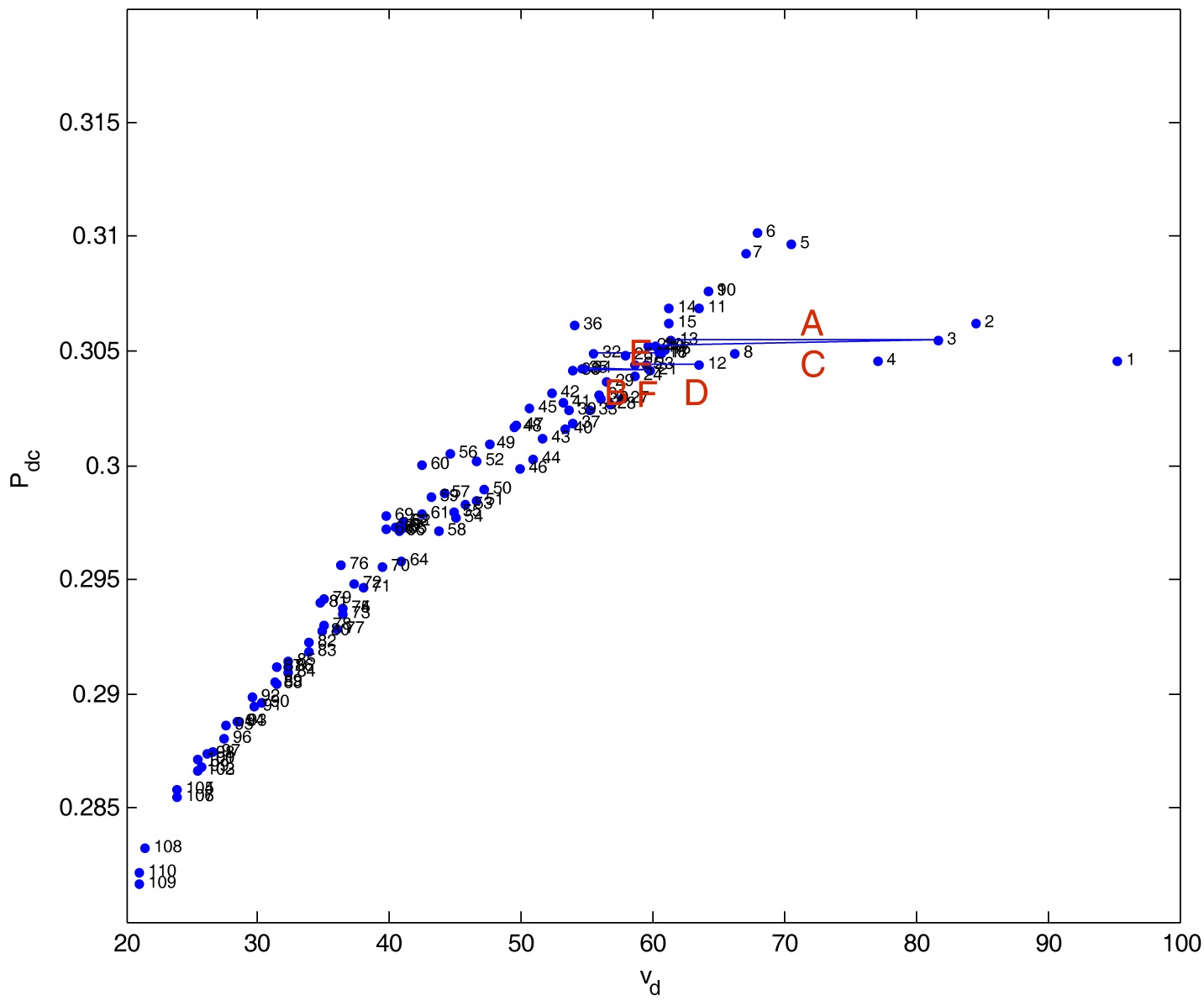
    We choose the Schott glass [12] for the design because of the large number of types of glasses that are available. The Abbe numbers of the different glasses have been ranked. There are 119 different optical glasses all with different prices. The price of N-BK7 is the lowest. The relative price (RP) is found by comparison and the results are indexed. To avoid using the most expensive types of glass in the design, the twenty-nine types with a relative price RP ≥ 17 as well as those with no marked prices are eliminated. The costs of glasses such as N-KZFS11, N-PK51, and N-LASF31A, are much higher than the others. Those with no marked prices are molding glasses or new types of glasses. The internal transmittance is the transmittance of light excluding reflection loss. The N-SF6HT and N-SF57HT glasses offer improved transmittance in the visible spectral range especially in the blue-violet area. Moreover, since the Vd, nd, and Pd,C of N-SF6HT and N-SF57HT are all the same as those of N-SF6 and N-SF57, the corrected chromatic aberrations will be almost the same. Thus we can neglect the N-SF6HT and N-SF57HT glasses. A total of seventy types of glasses were chosen for doublet prisms design to correct chromatic aberration.

       2.4. Merit Function

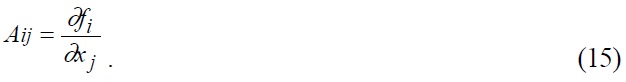
    In Eqs. (2) and (3), it can be seen that the there is a difference in the deviation angles between the real ray and the paraxial ray. The deviation angle of the paraxial ray is unconcerned with the incident angle I1, but the deviation angle of the real ray is related to the incident angle I1. When the incident angle increases, the real and paraxial chromatic aberrations will be very different. The real chromatic aberration is corrected for optimization. The damped least-squares method [13-15] is applied for an optimization design of the chromatic aberration. A merit function is defined as the summation of the squared values of the weighting differences between the aberrations and their target values. The formula can be written as

    image

    where m is the total summation number; the wi is the weighting factor; ei is the aberration and ti is the target value. We define the function fi(x1, x2, ‥‥, xn) as

    image

    Before optimization, the n variables are denoted as x10, x20, ···., xn0; the m aberrations before the optimization are f10, f20, ···., fm0. After the optimization process, the variables are denoted as x1, x2, ···, xn, and the aberrations as f1, f2, ···., fm. Here, we define a matrix A, in which the elements are

    image

    We then get the equation

    image

    where AT is the transpose matrix of A; I is a unit matrix, p is a damping factor; and f0 is the matrix containing the elements f10, f20,···. fm0. If x and x0 are the matrices containing the elements x1, x2, ···, xn, and x10, x20, ···, xn0, respectively, we can obtain

    image

    III. RESULTS

       3.1. Minimizing the Paraxial Chromatic Aberration

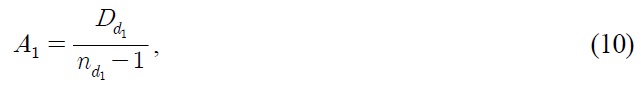
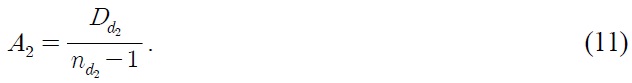
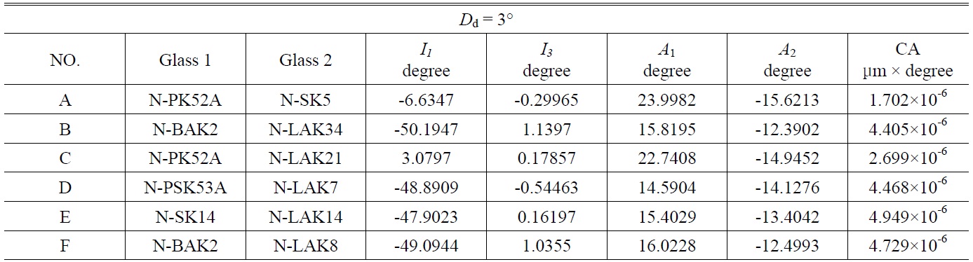
    The doublet prisms have two apex angles. The angle of deviation of d line is 3°, and the primary color is eliminated. The steps are repeated to reduce the secondary spectra of the doublet prisms. Using Eq. (12), the correct doublet prisms combination can be found by choosing the smaller (PdC1-PdC2) and the larger (Vd1-Vd2). When the (PdC1-PdC2)/(Vd1-Vd2) is close to zero, the chromatic aberration is smaller. Figure 2 shows the relative partial dispersion with respect to the Vd number. We chose six groups from A to F for minimizing the paraxial chromatic aberration. The design results are listed in Table 1, where the CA is the area of the chromatic aberration curve. Figure 3 shows the chromatic aberration curves. The

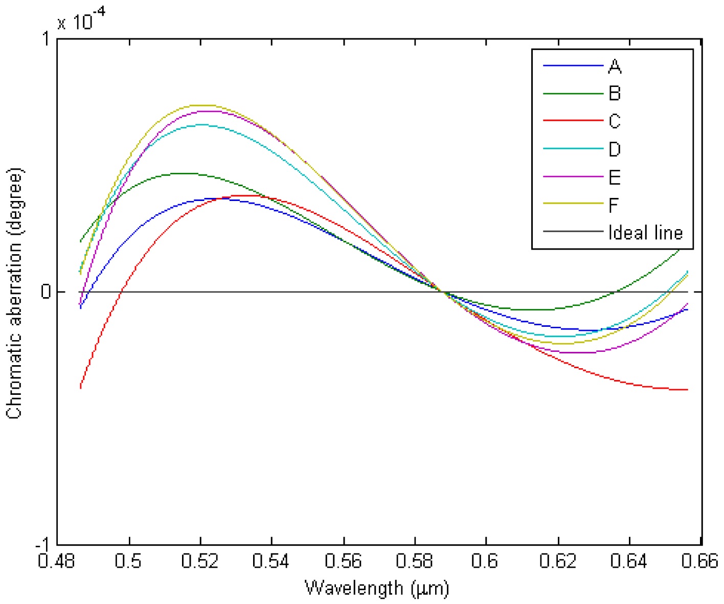
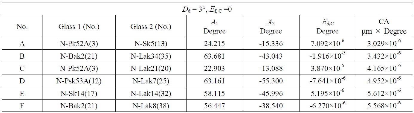
    [TABLE 1.] Design data and area of paraxial chromatic aberration curves for doublet prisms A To F

    label

    Design data and area of paraxial chromatic aberration curves for doublet prisms A To F

    [TABLE 2.] Initial values for optimization of the doublet prism design (group A)

    label

    Initial values for optimization of the doublet prism design (group A)

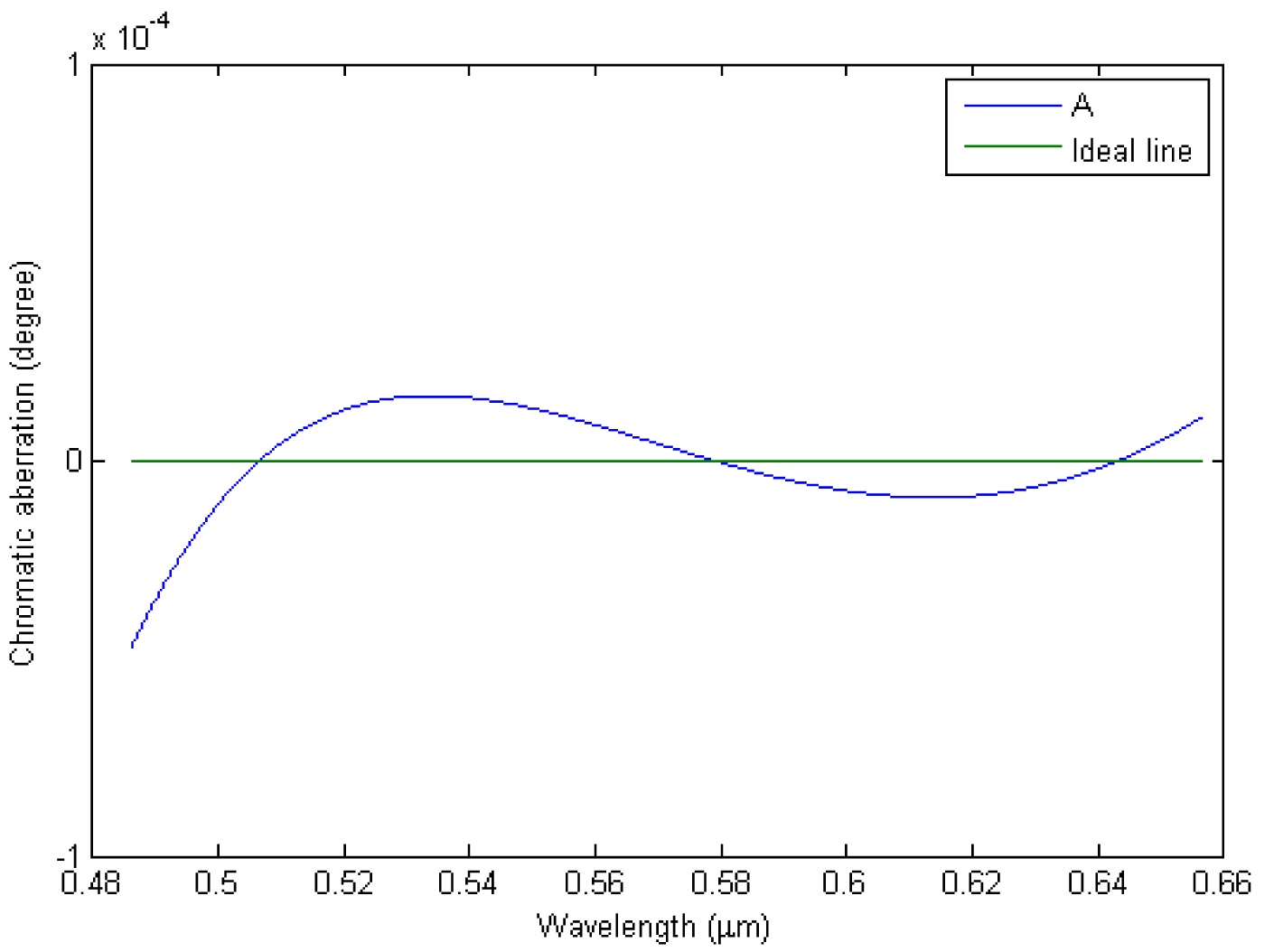
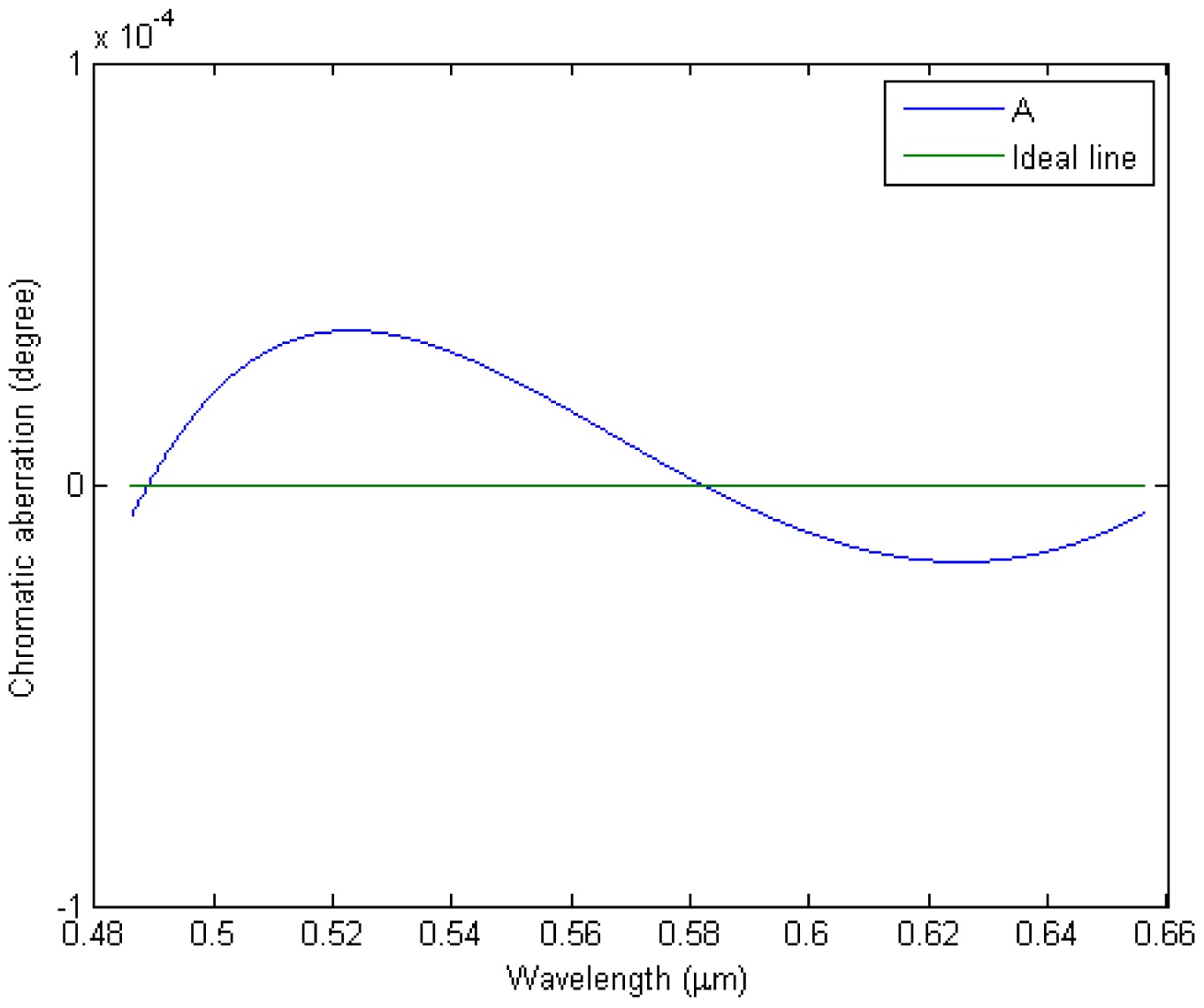
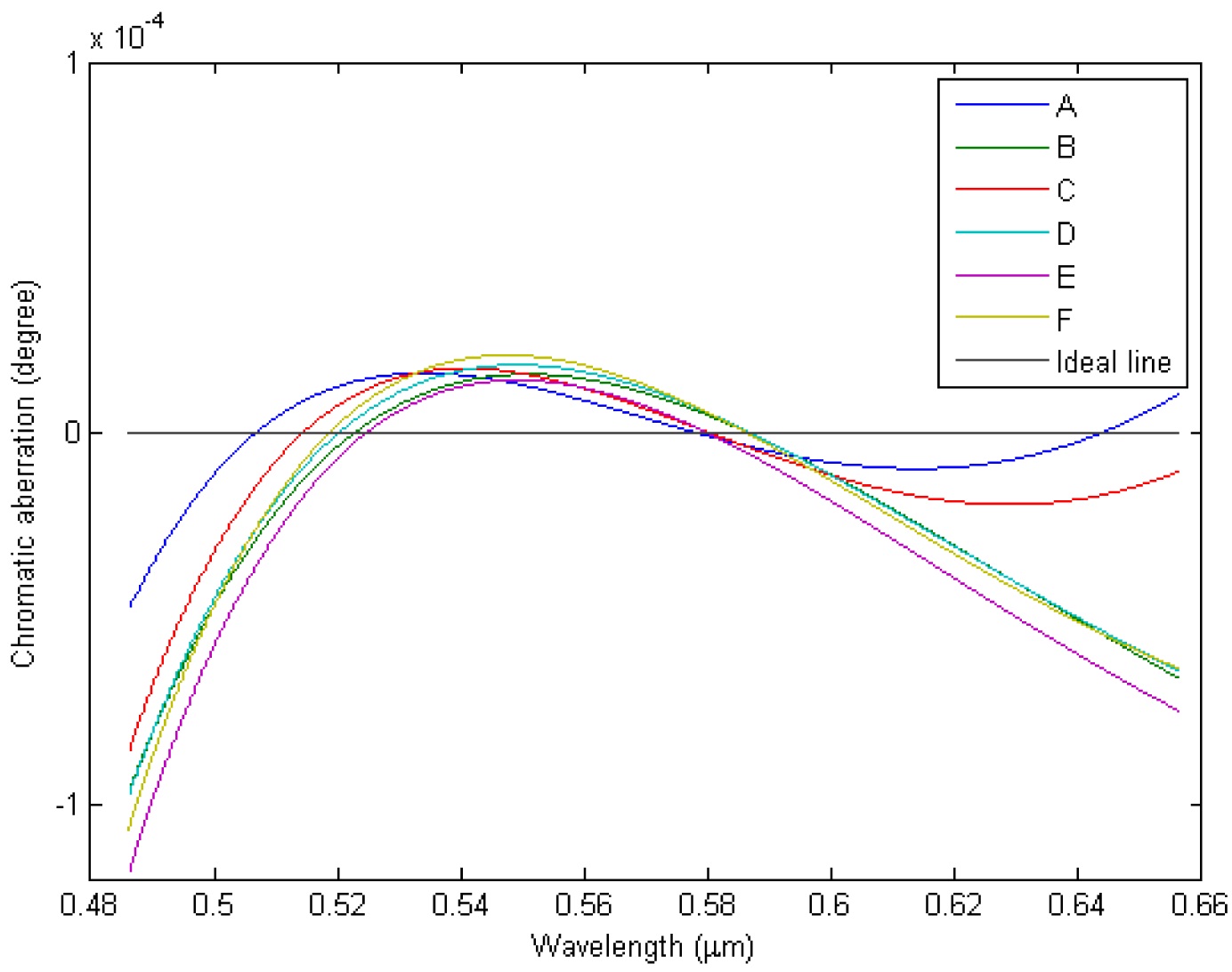
    horizontal ideal line, which denotes the angle of deviation of d line is 3°, has been set to zero for the chromatic aberration. The other lines are described as the chromatic aberration of doublet prisms groups from A to F.

       3.2. OPtimization Design For The Real Chromatic Aberration

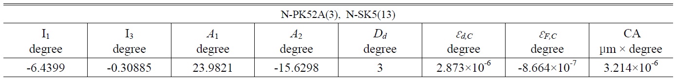
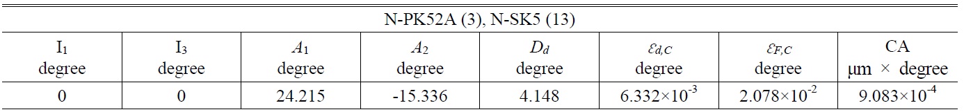
    We choose group A from Table 1 as an example as the initial value. The doublet prisms are made of N-PSK52A and N-SK5 glasses. We set I1 and I3 as the incident angles for the first surface of the first and the second prisms, respectively; A1 and A2 are the apex angles of the first and the second prisms, respectively. An illustration of the ray tracing of the doublet prisms is shown in Fig. 4. At the initial values, we set I1 = 0, I3 = 0, A1 = 24.215°, and A2 = -15.336°, as listed in Table 2. We can calculate the Dd = 4.148°, εd,C = 6.332×10⁻³, εF,C = 2.078×10⁻², and CA= 9.083×10⁻⁴ for the real ray tracing. The Dd and chromatic aberrations between the real and the paraxial rays (εF,C, εd,C, CA) are very different. The real chromatic aberration is corrected by an optimization program.

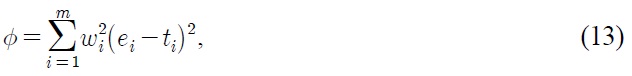
    The merit function consists of three terms. The first term is the deviation angle Dd of the real ray for the doublet prisms, the second is the real primary color aberration εF,C of the doublet prisms, and the last is the real secondary spectrum εd,C of the doublet prisms. If the target values are tDd=3, tεd,C=0, and tεF,C=0, then the merit function is given by

    image

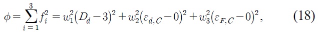
    where the weighting factors are w1= 1, w2= 20, w3= 20, respectively. During the doublet prisms optimization, we

    will consider some sort of aberration balance, a sensible choice of weighting factors is essential if we are to achieve the best possible performance. In the optimization process, we think that two aberrations of εd,C and εF,C are more rigorous than that of Dd, and then the target values of both |εd,C| and |εF,C| are twenty times smaller than those of |Dd-3|. It is therefore sensible, often but not always, for weighting factors to be smaller for larger target values.

    We use four variables as x1, x2, x3, and x4, to represent the incident angle I1 of the first prism, the incident angle I3 of the second prism, the apex angle A1 of the first prism, the apex angle A2 of the second prism, respectively. Before optimization, the variables are denoted as x10, x20, x30, and x40, which correspond to I1= 0, I3= 0, A1= 24.215, and A2= -15.336, respectively. The optimization results are listed in Table 3, and the real chromatic aberration curve is shown in Fig. 5.

    Except for fixing the deviation angle of real ray Dd = 3°, we can optimize the area CA of the real chromatic aberration curve to obtain an optimization design. The merit function is defined as

    image

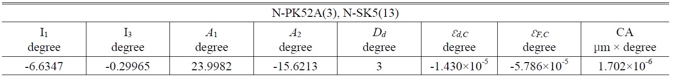
    [TABLE 3.] Design results (group A) for target values: tDd=3, t?d,D=0, and t?F,C=0

    label

    Design results (group A) for target values: tDd=3, t?d,D=0, and t?F,C=0

    [TABLE 4.] Design results (group A) for target values: tDd=3, tCA=0

    label

    Design results (group A) for target values: tDd=3, tCA=0

    where the target values are tDd=3, and tCA=0. The optimized results are listed in Table 4, and the real chromatic aberration curve is shown in Fig. 6.

       3.3. Total Internal Reflection

    As mentioned before, figure 4 shows the ray tracing of the doublet prisms, where
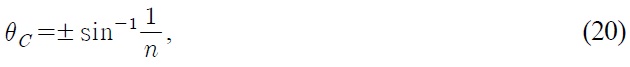
 I1, I1, A2, I4, and I4 are negative and A1, I2, I2, I3, and I3 are positive. When the incident angle of the first prism is I2 > θC, the total internal reflection of the ray appears. The critical angle θC is given by

    image

    where n is the refractive index of the prism.

    We choose group B from Table 5 as an example. The two types of glass used in the doublet prisms are N-BAK2 and N-LAK34, their refractive indices are nd1=1.53996 and nd2=1.72916, respectively, and the critical angles are θC1=40.494° and θC2=-35.332°, respectively. In order to avoid total reflection, the incident angle I1 of the first surface of

    the first prism must be

    image

    and the incident angle I3 of the first surface of the second prism is required to be

    image

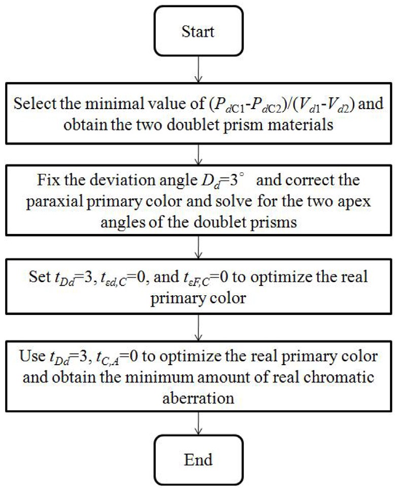
       3.4. Design of The Optimization Program

    A flow-chart of the optimization program for the doublet prisms design is shown in Fig. 7. First, the program selects (PdC1-PdC2)/(Vd1-Vd2), the minimal value of the doublet glasses. Second, the program uses the paraxial ray equations from Eq. (6) to Eq. (11) to fix the deviation angle Dd =3°, and eliminate the primary color. Then, the two apex angles are obtained. Third, the program sets tDd=3, t?dC=0, and t?F,C=0 to optimize the real primary color. Finally, tDd=3 and tCA=0 are used to optimize the area of the real chromatic aberration curve, until the real chromatic aberration is a minimum. The

    [TABLE 5.] Optimization designs for doublet prisms from group A to group F

    label

    Optimization designs for doublet prisms from group A to group F

    results for the optimized designs A to F are listed in Table 5. The chromatic aberration curves A to E corresponding to the optimal designs are shown in Fig. 8. This indicates that the proposed design method is effective in minimizing the chromatic aberration.

    IV. CONCLUSION

    A low-cost optimal double-prism method combined with the developed MATLAB program to correct chromatic aberration has been presented. In comparison of the doublet-prism designs shown in Tables 1 and 5, shows that the areas between the paraxial and real chromatic aberration curves are similar. We can quickly find the best combination of doublet prisms by choosing the materials with small differences in relative partial dispersion and large differences in Vd number, and minimizing the real

    chromatic aberration of doublet prisms by an optimization program.

참고문헌
  • 1. Kidger M. J. 2001 Fundamental Optical Design google
  • 2. Seong K., Greivenkamp J. E. (2008) “Chromatic aberration measurement for transmission interferometric testing” [Appl. Opt.] Vol.47 P.6508-6511 google cross ref
  • 3. Sutton L. E., Stavroudis O. N. (1961) “Fitting refractive index data by least squares” [J. Opt. Soc. Am.] Vol.51 P.901-905 google cross ref
  • 4. Stephens R. E. (1959) “Selection of glasses for three-color achromats” [J. Opt. Soc. Am.] Vol.49 P.398-401 google cross ref
  • 5. Robb P. N. (1985) “Selection of optical glasses. 1: two materials” [Appl. Opt.] Vol.24 P.1864-1877 google cross ref
  • 6. Sharma K. D., Rama Gopal S. V. (1983) “Design of achromatic doublets: evaluation of the double-graph technique” [Appl. Opt.] Vol.22 P.497-500 google cross ref
  • 7. Rayces J. L., Rosete-Aguilar M. (2001) “Selection of glasses for achromatic doublets with reduced secondary spectrum. I. tolerance conditions for secondary spectrum, spherochromatism, and fifth-order spherical aberration” [Appl. Opt.] Vol.40 P.5663-5676 google cross ref
  • 8. Rayces J. L., Rosete-Aguilar M. (2001) “Selection of glasses for achromatic doublets with reduced secondary spectrum. II. application of the method for selecting pairs of glasses with reduced secondary spectrum” [Appl. Opt.] Vol.40 P.5677-5692 google cross ref
  • 9. Banerjee S., Hazra L. (2001) “Experiments with a genetic algorithm for structural design of cemented doublets with prespecified aberration targets” [Appl. Opt.] Vol.40 P.6265-6273 google cross ref
  • 10. Hecht E. 2002 Optics P.187 google
  • 11. Malacara D., Malacara Z. 2004 Handbook of Optical Design P.253 google
  • 12. “Optical glass catalog” google
  • 13. Feder D. P. (1963) “Automatic optical design” [Appl. Opt.] Vol.2 P.1209-1226 google cross ref
  • 14. Wynne C. G., Worme P. M. J. H. (1963) “Lens design by computer” [Appl. Opt.] Vol.2 P.1233-1238 google cross ref
  • 15. Jamieson T. H. 1971 Optimization Techniques in Lens Design google
OAK XML 통계
이미지 / 테이블
  • [ FIG. 1. ]  Angle of deviation of a prism.
    Angle of deviation of a prism.
  • [ FIG. 2. ]  Pd,C - Vd mapping for the selected doublet prisms.
    Pd,C - Vd mapping for the selected doublet prisms.
  • [ FIG. 3. ]  Minimizing paraxial chromatic aberration curves for doublet prisms groups A to F.
    Minimizing paraxial chromatic aberration curves for doublet prisms groups A to F.
  • [ TABLE 1. ]  Design data and area of paraxial chromatic aberration curves for doublet prisms A To F
    Design data and area of paraxial chromatic aberration curves for doublet prisms A To F
  • [ TABLE 2. ]  Initial values for optimization of the doublet prism design (group A)
    Initial values for optimization of the doublet prism design (group A)
  • [ FIG. 4. ]  Ray tracing in the doublet prisms.
    Ray tracing in the doublet prisms.
  • [ TABLE 3. ]  Design results (group A) for target values: tDd=3, t?d,D=0, and t?F,C=0
    Design results (group A) for target values: tDd=3, t?d,D=0, and t?F,C=0
  • [ TABLE 4. ]  Design results (group A) for target values: tDd=3, tCA=0
    Design results (group A) for target values: tDd=3, tCA=0
  • [ FIG. 5. ]  Real chromatic aberration curve for group A for optimized target values: tDd=3, t?d,C=0, and t?F,C=0
    Real chromatic aberration curve for group A for optimized target values: tDd=3, t?d,C=0, and t?F,C=0
  • [ FIG. 6. ]  Real chromatic aberration curve for group A for optimized target values: tDd=3,tCA=0.
    Real chromatic aberration curve for group A for optimized target values: tDd=3,tCA=0.
  • [ TABLE 5. ]  Optimization designs for doublet prisms from group A to group F
    Optimization designs for doublet prisms from group A to group F
  • [ FIG. 7. ]  Flow chart of optimization program for doublet prisms.
    Flow chart of optimization program for doublet prisms.
  • [ FIG. 8. ]  Chromatic aberration curves A to E for the optimal designs.
    Chromatic aberration curves A to E for the optimal designs.
(우)06579 서울시 서초구 반포대로 201(반포동)
Tel. 02-537-6389 | Fax. 02-590-0571 | 문의 : oak2014@korea.kr
Copyright(c) National Library of Korea. All rights reserved.