Operating aircraft efficiently can significantly help to reduce their operating costs. However, the efficiency of the aircraft that are widely used today in the aviation industry is limited, due to their design constraints. Therefore, aircraft that are capable of morphing their wing forms are highly desired over conventional aircraft with fixed wings, since they can be operated efficiently at different flight profiles [1].
In the past, several aircraft have been designed that can change their wing surface plan form, for optimal performance in flying at different flight conditions. For instance, the Grumman F-14 [2] can change its sweep angle from 20° to 67.5° for high speed flight, of up to Mach 2.4. The Rockwell International B-1 [3] can sweep its wings forward, during takeoff, landing and high altitude cruise, and the wings are swept aft, for subsonic and supersonic flight. The XB-70 supersonic bomber [4] can fold its wingtip while travelling at high speed, in order to trap the shockwave under the wings. The folded wing tip could also be used for lateral directional stability, substituting the need for a larger and heavier vertical fin.
Current morphing aircraft concepts being developed involve far more radical changes in their wing shape, so as to perform efficiently at varying flight conditions. The Hyper- Elliptic Cambered Span (HECS) morphing wing concept, being developed by researchers at NASA, can provide 15% better lift to drag ratio, compared to planar and elliptical wings [5]. The NextGen Aeronautics variable sweep and variable root chord concept, also known as the bat wing concept [6], involves sweeping of the wing from 15° to 45°, for efficient high lift, cruise and dash operation. Furthermore, the stealth operation-capable folding wing concept being developed by Lockheed Martin can vary its span by 100%, and plan form area by 120%, for cruise and loiter missions [7]. Its unfolded configuration allows the aircraft to be used for efficient loitering, whereas folding the wing reduces the wing’s surface area, for flying at high speed.
There are many challenges faced by such radical morphing concepts. Among them, occurrence of dynamic aeroelastic instability, such as the flutter of lifting surfaces, is of serious concern for the development of morphing aircraft. Such instability can result in the disastrous failure of flight vehicle structures, such as the vertical fin flutter incidents that occurred in the F117 stealth fighter, and E-6 Tacamo [8]. Therefore, it is of utmost priority to investigate the flutter characteristics of morphing aircraft, to ensure that the newly developed morphing wings are safe and reliable.
The flutter behavior of Lockheed Martin’s folding concept is the main research interest discussed in this paper. Research done by Zhao and Hui [9] showed that structural and aerodynamic characteristics of a folding wing are largely dependent on its folding angle. As a result, its flutter speed is also characterized by its folding angle. Additionally, unstable mode changes, as the folding angle is increased, and the flutter behavior of the folding wing,
are strongly influenced by structural and aerodynamic damping. Mathew et al. [10] found that the folding wing’s folding angle, hinge stiffness and weight are all strongly inter-related to each other. Its bending modes are considerably influenced by the stiffness of the hinge. The bending modes of the folding wing are dominated by the structural stiffness, for higher spring stiffness at higher folding angles.
In this paper, modal/flutter analyses of a folding wing are performed, and these modal/flutter characteristics are validated with results from previous research [9]. Then, to develop folding wings with better flutter characteristics, further investigation is performed, by varying inboard/ outboard folding angles. Through this research, combinations of inboard/outboard folding angles are determined, to avoid the flutter phenomenon, as the wing configuration is changed.
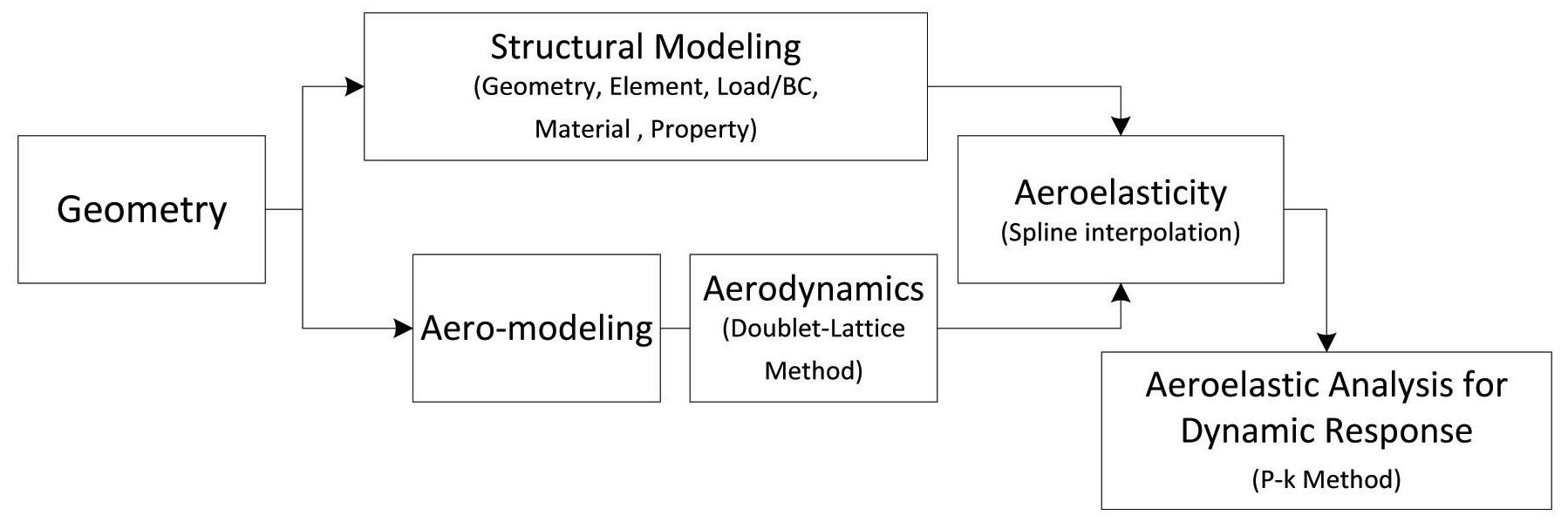
In order to investigate the flutter phenomenon of a folding wing, structural and aerodynamic models are created using MSC.PATRAN FlightLoads. The structural model of the folding wing is composed of the geometry, element, load/ boundary conditions (BC), material, and property. The aerodynamic model contains the aerodynamic conditions/ properties for the flutter analysis. The research discussed here deals with subsonic flow; therefore the subsonic surface aerodynamic theory Doublet Lattice Method (DLM) [11] implemented in MSC.NASTRAN is used, for calculating the aerodynamic forces.
Aerodynamic grids points and structural grid points do not coincide with each other. Therefore, spline approximation is used, to obtain aerodynamic forces on structural grid points. Finally, MSC.NASTRAN is used for flutter analysis of the folding wing, using the
2.2 Flutter Solution Method: p-k Method
In this

where, [
Aerodynamic forces are given by the summation of motion dependent and motion independent aerodynamic forces, and can be written as

Then by substituting Eq. (2) in Eq. (1), and assuming the unsteady aerodynamic forces depend only on displacements, the equation of motion can be rewritten as

where,
By using

and substituting it in Eq. (3), the eigenvalue problem is transformed to
In Eq. (5), by substituting

the
where,

where,
One key advantage of using the
Using the
3. Folding Wing Flutter Characteristics
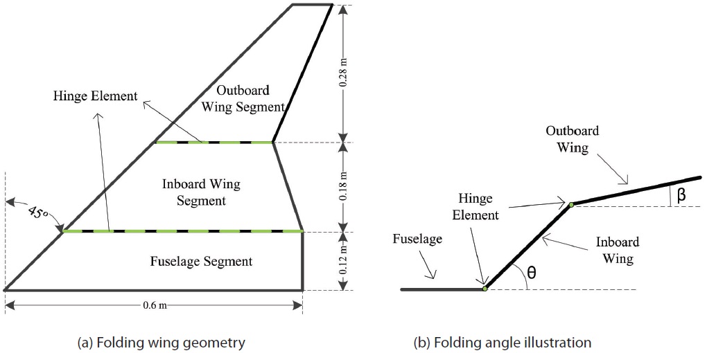
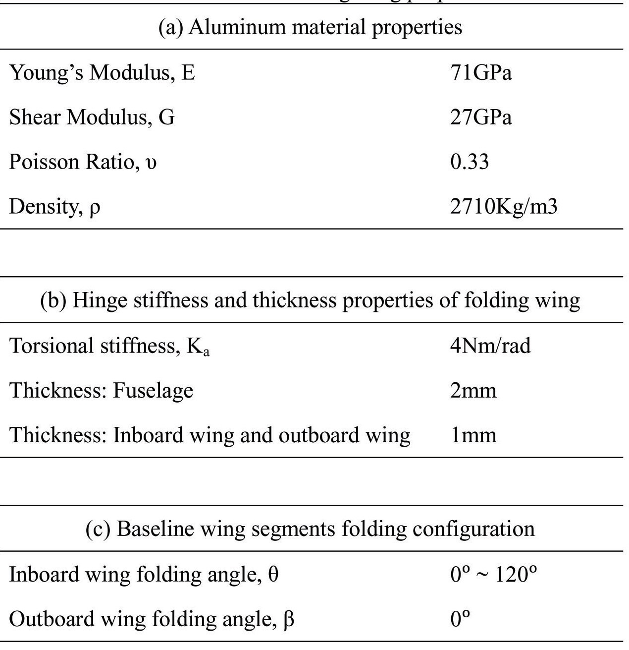
The structure of the folding wing consists of: fuselage, inboard folding wing and outboard folding wing, as shown in Fig. 2 (a). These three substructures are connected to each other by a hinge element, with a torsional stiffness of 4Nm/rad. The folding configuration of the folding wing is illustrated in Fig. 2 (b). For the baseline folding wing case, the inboard wing segment folds from 0° to 120°, while the outboard wing rotation angle remains at 0°.
Modeling of the isotropic folding wing structure is done in MSC.PATRAN FlightLoads, with respect to the dimension presented in Fig. 2 (a). The fuselage, inboard wing and the outboard wing, with thickness of 2mm, 1mm and 1mm, respectively, are assigned with aluminum material properties. A clamped boundary condition is applied to the fuselage section. Properties of the baseline folding wing are tabulated in Table 1.
3.2 Baseline Folding Wing Flutter Analysis
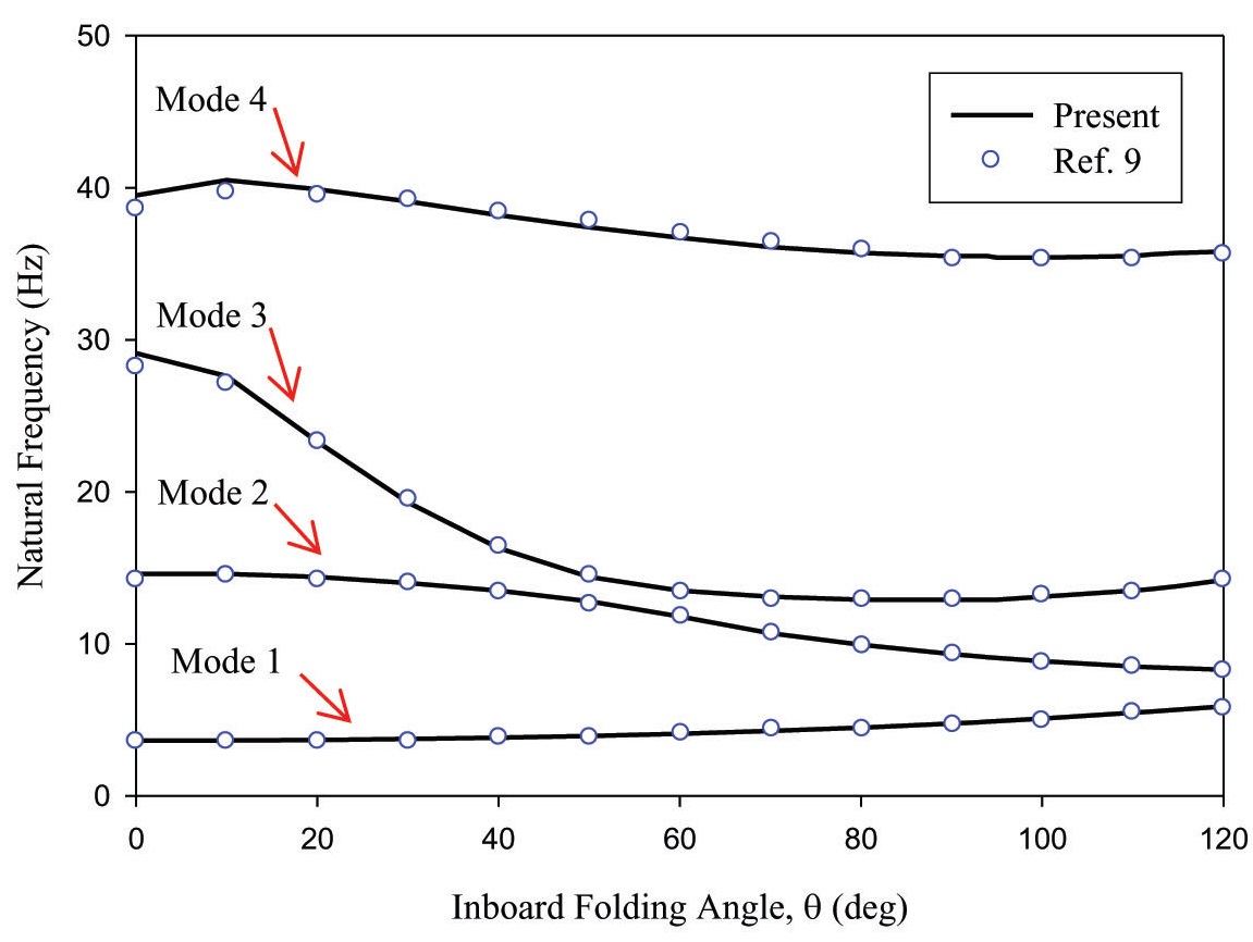
The modal analysis of the baseline folding wing is performed using MSC.NASTRAN solution sequence SOL 103. Figure 3 shows the changes in natural frequency of the four lowest modes of the folding wing, as the inboard wing folding angle (IWFA) is increased from 0° to 120°.
Significant change in natural frequencies can be observed, due to changes in the wing’s structural geometry. The 3rd mode natural frequency is the most affected, with increase in the IWFA. The present modal results, when compared
with the reference results [9], show the results to be in good agreement with each other.
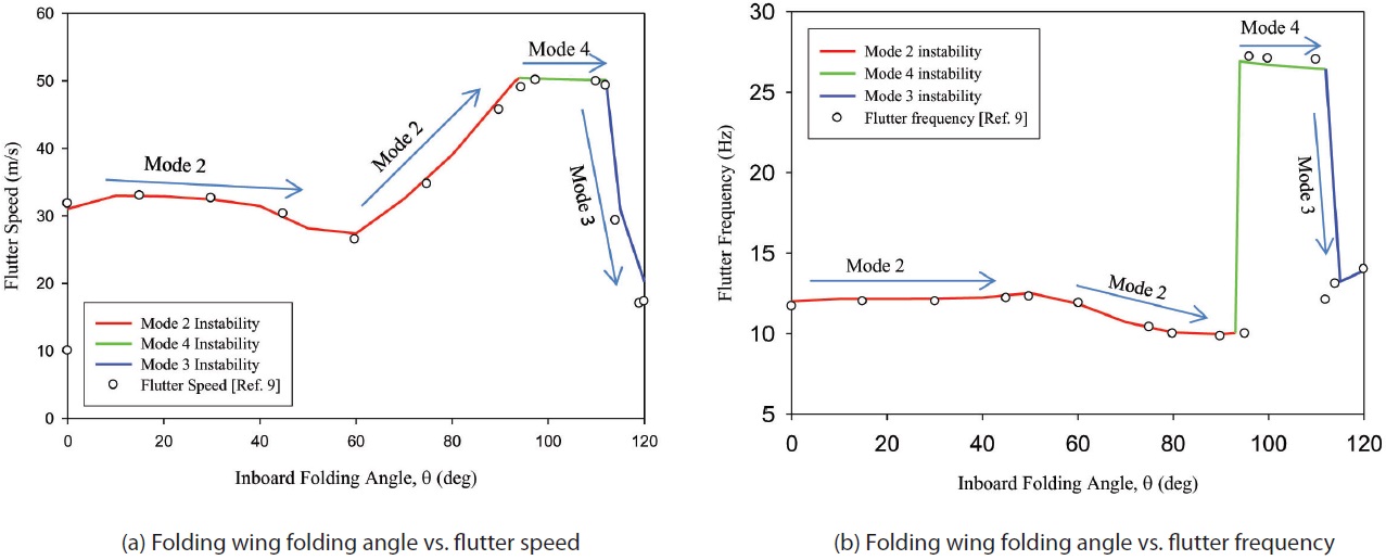
Flutter analysis is carried out in MSC.NASTRAN, using solution sequence SOL 145. The flutter speed and flutter frequency of the folding wing are calculated for IWFA from 0° to 120°, and plotted as shown in Fig. 4.
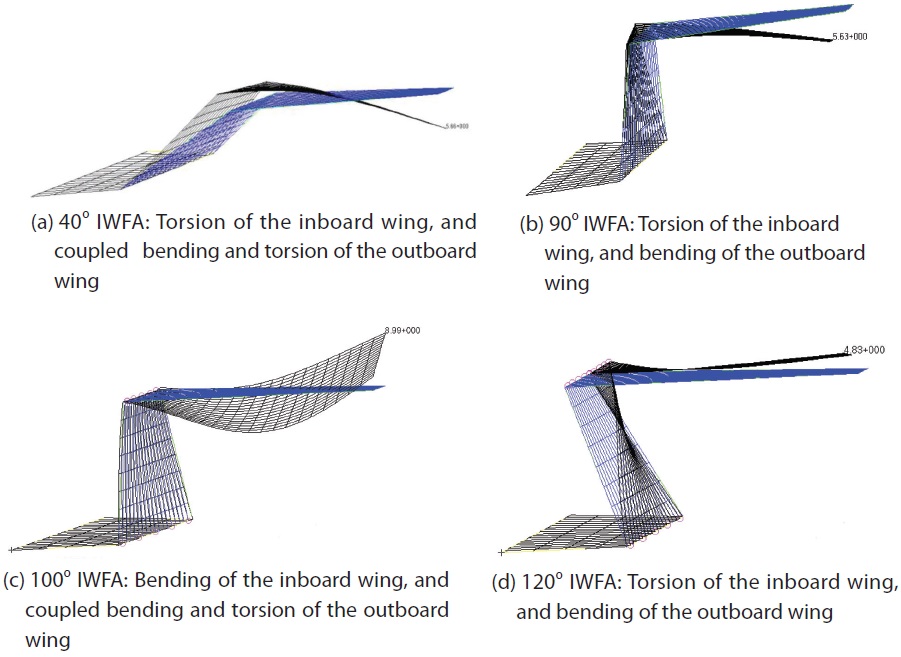
Varying the IWFA from 0° to 120° results in drastic changes in the flutter speed and frequency of the folding wing, as shown in Figs. 4 (a) and (b) respectively. It is observed that the flutter characteristics of the folding wing structure are dominated by instability of the 2nd mode for an IWFA between 0° to 93°, 4th mode for an IWFA between 94° to 112°, and 3rd mode beyond 112° of the IWFA.
For the region between 0° and 60° of IWFAs, flutter results in torsion of the inboard wing, and coupled bending and
[Table 1.] Baseline folding wing properties

Baseline folding wing properties
torsion of the outboard wing, due to second mode instability, as visualized in Fig. 5 (a). Flutter instability of the 2nd mode occurs in this region, due to the merging of the 1st and 2nd modes. In the folding angle against flutter speed plot shown in Fig. 4 (a), flutter speed increases slightly by 31m/s to 33m/s, between IWFAs of 0° to 20°. When the IWFA is increased from 20° to 60°, the folding wing flutter speed decreases by 18%, to about 27m/s. Minor change in flutter frequency can be observed in Fig. 4 (b), i.e. it remains at about 12Hz.
Whereas, the second mode instability dominating the flutter characteristics between 60° and 93° IWFA, is due to the merging of the 2nd and 3rd modes. This results in the torsion of the inboard wing, and the bending of the outboard wing, as shown in Fig. 5 (b). Increase in the IWFA from 60° to 93° results in sharp increase in flutter speed, from 27.4m/s to 49.9m/s, while the flutter frequency drops by about 15% to 9.958Hz.
4th mode instability occurs between IWFAs of 94° and 112°, due to merging of the 3rd mode and 4th mode. In this folding angle region, 4th mode instability results in the bending of
the inboard wing, and coupled bending and torsion of the outboard wing, as shown in Fig. 5 (c). The flutter speed and flutter frequency remain relatively constant in this region, at about 50m/s and 26Hz, respectively.
Finally, in the IWFA region beyond 112° 3rd mode instability occurs, due to the merging together of the 2nd and 3rd mode. Merging of the 2nd and 3rd modes results in a mode shape of the folding wing similar to that for the case between an IWFA of 60° and 93° i.e. the torsion of the inboard wing, and the bending of the outboard wing. The mode shape for this case is visualized in Fig. 5 (d). Beyond 112° IWFA, change in dominant instability mode from the 4th mode to
3rd mode causes both the flutter speed and flutter frequency to drop, from 50.1m/s to about 20.3m/s, and from 26.441Hz to 13.916Hz, respectively.
The present flutter results of the baseline folding wing are compared with the reference results [9], and the results are found to be in close agreement. From the present result, it can be concluded that the purpose of using a folding wing for high speed operation can be constrained, due to the flutter phenomenon. Therefore, in the following sections, the flutter speed of the folding wing is investigated, by varying both the inboard and outboard wing, to improve its flutter characteristics.
4. Flutter Analysis of a Folding Wing with Varying Inboard/Outboard Wing
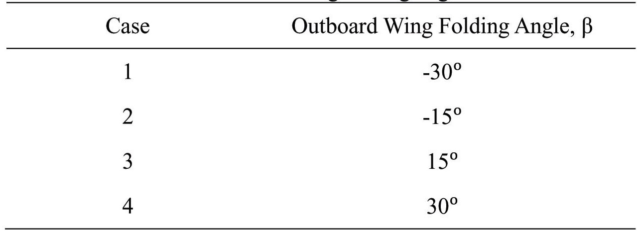
In order to enhance the flutter characteristics of the folding wing, further analyses are done, by varying its outboard wing folding angle (OWFA), independent of the IWFA. Table 2 shows four cases of OWFA, for which flutter analyses are performed. A hinge stiffness of 4Nm/rad, similar to the baseline folding wing, is used for the flutter analysis.
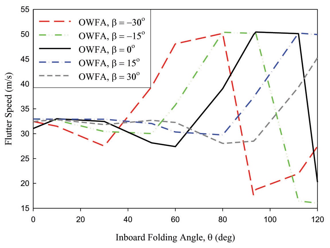
Figure 6 shows the flutter speed for the IWFAs from 0° to 120°, and for the OWFAs from -30° to 30°, compared with the baseline flutter characteristics. Varying the OWFA causes the IWFA, at which the unstable mode dominating the flutter characteristics shifts from one mode to another, to change. As a result, folding the outboard wing causes the flutter characteristics of the folding wing to drastically differ, from the flutter characteristics of the baseline folding wing. For instance, compared to the baseline flutter characteristics, decreasing the OWFA below 0° causes the flutter instability mode to change at a lower IWFA; and increasing the OWFA above 0° causes the flutter instability mode to change at a higher IWFA. As a result, it can be observed that, as the
[Table 2.] Outboard wing folding angle case

Outboard wing folding angle case
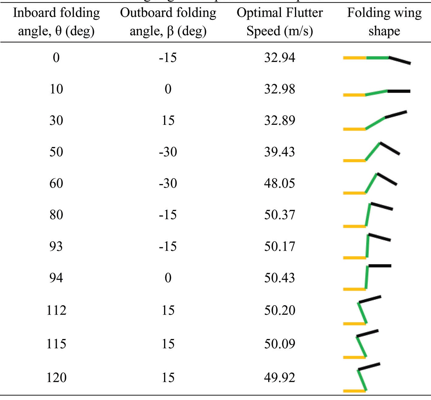
[Table 3.] Combination of inboard and outboard folding angles for optimal flutter speed

Combination of inboard and outboard folding angles for optimal flutter speed
OWFA is decreased from 0° to -30°, the baseline flutter characteristics shift leftwards on the graph; and as the OWFA is increased from 0° to 30°, the baseline flutter characteristics shift rightwards.
This phenomenon makes it possible to select the best possible combination of IWFA and OWFA for operating the folding wing at maximum possible speed, as the inboard wing is folded from 0° to 120°. This allows the folding wing to be operated safely within a pre-determined region, with respect to the inboard/outboard folding angle combinations.
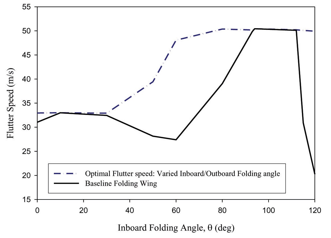
Inboard/outboard folding angle arrangements that deliver the best flutter behavior of the folding wing are listed in Table 3. Figure 7 shows the optimal flutter speed attainable through the morphing of inboard/outboard wings, compared with the baseline folding wing flutter characteristics. From Fig. 7, it can be observed that about 40% increase in flutter speed can be achieved at 50° IWFA, while flutter speed of about 50m/s can be maintained for the IWFA region between 60° to 120°. From the results presented in this section, seen that the flutter speed can be improved as the IWFA is changed, through variation in the OWFA. This characteristic can be especially beneficial, in
allowing the folding wing to fold its wing, in order to fly at higher speed.
In this paper, improvement of the flutter characteristics of a folding wing is proposed, through variation of the OWFA, independent of the inboard wing segment. Firstly, baseline isotropic folding wing flutter analysis is carried out, using the
By varying the OWFA, along with the inboard wing segment, it is found that the baseline folding wing’s flutter characteristics shift either to the left, when the OWFA is decreased, or to the right, when the OWFA is increased. Utilizing this shift in flutter characteristics, combinations of the inboard/outboard wing folding angles, as shown in Table 12, can be determined, for optimal flutter speed of the folding wing, which can provide better flutter performance, as the folding wing is morphed.
From the results presented in this paper, it can concluded that the flutter of folding wings can be avoided, for: (i) missions involving loitering, where an unfolded configuration is used for low speed flight, and (ii) high speed cruise missions, by varying both the inboard and outboard wings’ folding angles. This enables the folding wing concept to be used as efficiently, and as safely, as possible.