In the field of precise attitude determination for spacecraft in near Earth orbit, it is possible to utilize many attitude sensors: 3-Axis Rate Gyros, Star-Sensor, Sun-Sensor, Magnetometer, Infrared Horizon-Sensor, etc. These sensors offer various kinds of information, and thus lead to different attitude determination strategies. Methods such as the optimized TRIAD method [1], Q-method [2], Unscented Kalman Filter (UKF) [3], as well as the FKF method described in this paper, are prevalent. Basically, they are implemented according to the kinematic model of spacecraft attitude motion, achieving information fusion and global optimal estimation. By taking advantage of multi-sensors’ information while avoiding their disadvantages, these methods acquire higher attitude determination accuracy, and higher malfunction tolerance capacity. Thus it is possible to obtain attitude estimation that is better than single sensor observation accuracy. Or in other words, to fulfill the same attitude determination accuracy requirement of a system, it presumably decreases the demand in performance indices of each sensor, remarkably reducing the total budget of the attitude determination system [4]. However, the characteristics of different sensors differ greatly. As for the three attitude sensors utilized in this paper: 3-Axis Rate Gyros have excellent performance in a short period, whereas the residuals of observation attitude will accumulate quickly, and result in unacceptable accuracy in the long term; GPS is lower in price and mass, but it will be jammed easily by complicated space circumstance and high-dynamic relative motion between GPS satellites and the spacecraft; and Star- Sensor is known to be the best attitude sensor, however, it will be interrupted by sunlight, and reflective light from the earth. What is more, it is extremely expensive, exerting great pressure on the attitude determination system budget [5].
Another complex problem is the information fusion strategy of sensors. Generally speaking, the Kalman filter is a classical recursive filter, with good performance in dealing with white noise, and achieving optimal estimation [6]. To cope with the fusion process of useful information, Pearson issued the Federated Kalman Filter method, which introduces a process of erecting several subsystem filters, and centralizing the final information fusion step in a main filter, which eventually outputs the global estimation of a complex system [7]. Besides, these sensors have different update rates, bringing unavoidable interference to the ultimate information fusion process. To utilize all these information effectively, a variable step size state prediction Kalman filter is established. It updates and predicts a sensor’s state, when the sensor is in update gaps. When all the sensors’ observation data are accessible, their data are then allowed to be involved in a filtering process [8].
This paper is organized as follows: In section 2, two subsystem Kalman filters are established. In section 3, an FKF is established to acquire global estimation, and fault tolerant design is added, on the basis of
The attitude determination residuals in quaternion form are set as main state variables, while the biases between the GPS’s outputted attitude and estimated attitude are set as observation variables.
2.1.1 State Equation
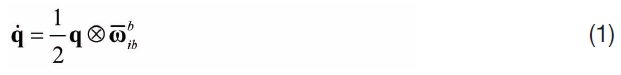
The state equation is designed by kinematic attitude motion, and is described in quaternion form as:
where,
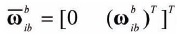
means angular rate. The bias between real attitude quaternion

is set as Δq=[Δ

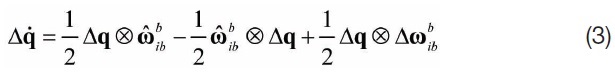
Substituting equation (2) into equation (1), the following equation is obtained:
where,

denotes the residual error of the angular rate. According to the criterion of quaternion multiplication:
The error quaternion is such a small value that Δq=[Δ
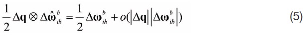
where,
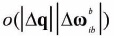
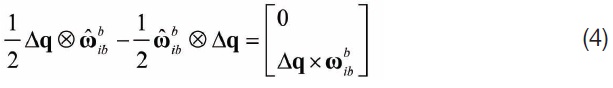
denotes a high-order infinitesimal value. Neglecting the second-order and subsequent infinitesimal segment, the linearized quaternion equation is described as:
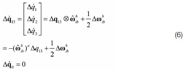
The superscript
On the basis of the gyro’ observation equation, equation (6) is transformed into:
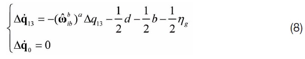

Thus, the state equation is described as below,

where,
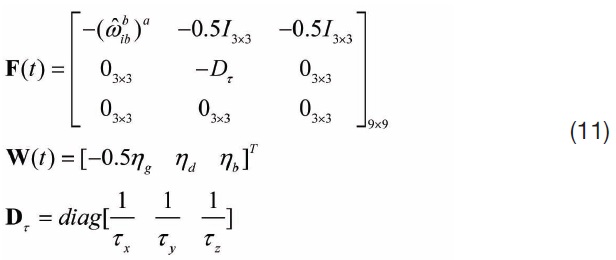

where, Φ

where,

where, Q

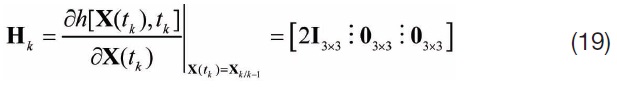
2.1.2 Observation Equation
The output of the GPS dual-baselines attitude determination system is in Euler-angle form. The residuals (difference between GPS observed attitude and estimated attitude) of GPS observation are selected as the observation variables in the Extended Kalman Filter.

Then, the observation equation is described as below:

Equation (17) is then linearized into:

where, H
V

R
2.2 Gyros/Star-sensor Kalman Filter
In this filter, the residuals between the star-sensor’s attitude observation (in quaternion form) and estimated attitude are set as observation variables. To correspond to the estimated attitude, it is necessary to transform the quaternion attitude into Euler angles, as described in the following equations:
Firstly, all the quaternion must be in unit vector form:
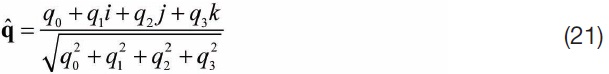
Thus, the Euler attitude can be calculated by:
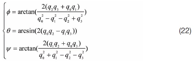
where,
Two Kalman filtering strategies are utilized in this paper: the variable step size state prediction Kalman filter and the Federated Kalman Filter.
3.1 Variable Step Size State Prediction Kalman Filter
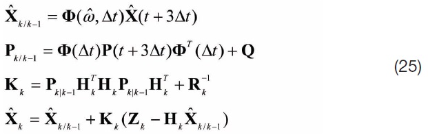
Different attitude sensors have different update rates, so it is crucial to utilize their data at maximum efficiency. In this paper, the gyros have a much higher update rate (20Hz), than the GPS (1Hz) and star-sensor (5Hz). In the variable step size state prediction Kalman filtering process, if the observation data of the GPS and star-sensor are unavailable, only the filters’ state variables are updated. As soon as the observation information is accessible, both state and observation variables are simultaneously updated.
3.1.1 Prediction without Observation Update
During the update gap of GPS and star-sensor at instant

where, Δ

is the state transition matrix. The prediction of error covariance matrix is described as:

3.1.2 Observation Update
Taking the star-sensor as an example, the star-sensor’s output is possible at instant
3.1.3 Calibrating Quaternion and Gyros’ Drift
After acquiring the optimal prediction state:

Calibrating the gyros’ time related drift, and constant drift:
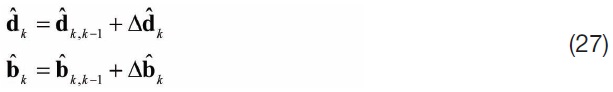
Thus the calibrated state in quaternion form is:

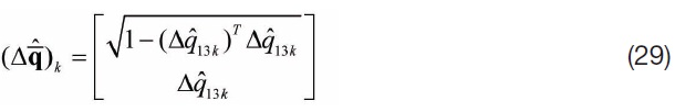
Considering the constraint that the magnitude of quaternion equals to 1:
3.2 Federated Kalman Filtering Strategy
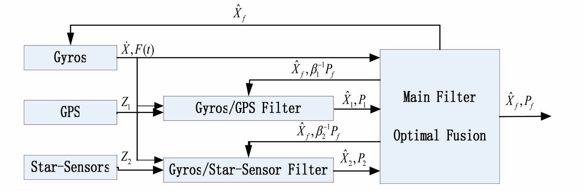
The Federated Kalman Filter consists of two independent subsystem filters, and one main filter, which fuses the subsystem filters’ information, and outputs the global estimation. It introduces the feedback of global estimation, and leads to a higher fault tolerant capacity.
3.2.1 Filtering Strategy
Fig. 1 describes the FKF designed in this paper.
The output of the subsystem is the state estimation
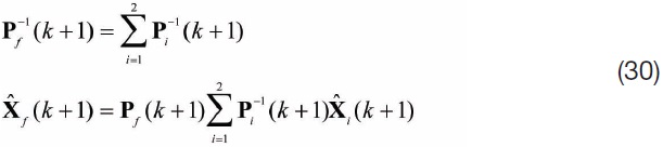
The significance of this method is obvious: if the precision of

is very bad, namely P

to final estimations should be very small. It is also significant to choose appropriate information allocation coefficients, while utilizing FKF [10]. In this paper, an adaptive coefficient choosing strategy is used:
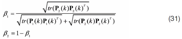
where,
Then, these feedbacks are utilized, to replace the subsystems’ filtering information, when global estimation is obtained after fusion of the subsystem’ state and error covariance matrix in the main filter.

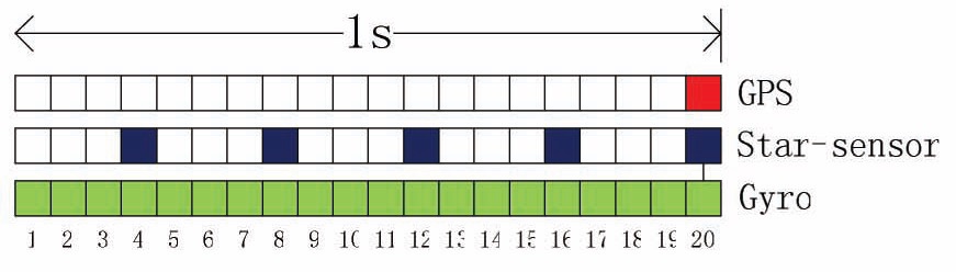
The update sequence of three sensors in 1 second is described in Fig. 2.
Obviously, all three sensors update at the instant when the GPS updates. It is a cycle of an integral FKF filtering process.
3.2.2 Malfunction Warning Factor
A malfunction warning factor, for checking whether or not a subsystem meets malfunction, is indispensable. There are two main checking methods: state
As for a subsystem Kalman filter, its residual is:

where, the state vector is predicted by the equation:

According to the filtering theorem, the residual is white noise with dispersion, as:

Assuming a malfunction function as:

It follows a

where,
Obviously, when malfunction occurs in a subsystem, its output should not be input into the main Kalman filter, or at least its weight should be decreased significantly. In this paper, the former conducting method is utilized, and the corrected output of FKF is utilized to replace the malfunctioned subsystem’s observation information. Assuming that the first subsystem goes wrong, all its information should be ignored. Then the final estimations of the system state variables are:

Updating the malfunctioned subsystem’s observation information as:

These two procedures assist in decreasing the impact of malfunction to a maximum extent.
The main performance indexes of the three sensors are described in Table.1.
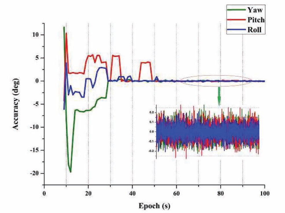
Fig. 3 describes the attitude determination accuracy, by utilizing the GPS only.
Obviously, the attitude determination accuracy is very low, before the double-differenced integer ambiguities are fixed by the LAMBDA method [13]. However, with the progressive improvement of the fixing success rate, the determination accuracy tends to be much better, with the best statistical accuracy of (0.08°, 0.08°, 0.06°, STD) in Euler angles. Thus, the time of successfully resolving the integer ambiguity must be considered. In the following segment of this paper, all GPS observation data is collected, after the LAMBDA method has consecutively worked for more than 70 seconds (the time of 100% fixing success rate, got by 1000 times Monte Carlo
[Table 1.] Simulation parameters
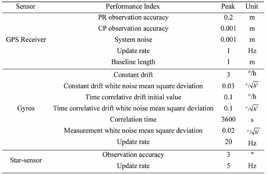
Simulation parameters
statistical result).
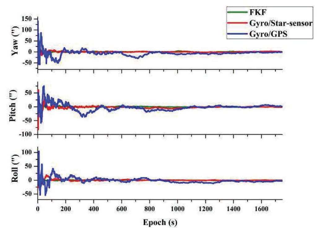
Fig. 4 describes the attitude determination accuracy trends of the two subsystem filters and FKF.
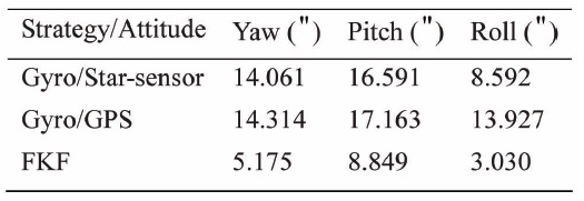
In Fig. 4, the blue line stands for the accuracy of the Gyros/GPS filter, the red line represents the Gyros/Star-sensor filter, and the green line denotes the final accuracy of the FKF. Clearly, the accuracy of the Gyros/Star-sensor filter converges quickly, while that of the Gyros/GPS converges much slower. FKF’s accuracy almost coincides with that of the Gyros/Star-sensor. Their statistical results are illustrated in Table 2.
The final global estimation of FKF nearly approaches the Gyro/Star-sensor’s result. That is mainly because both gyros and star-sensor are of much higher observation accuracy than the GPS, thus the Gyro/Star-sensor subsystem occupies a larger weight in FKF. In this process, the fault warning criteria (
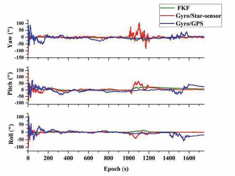
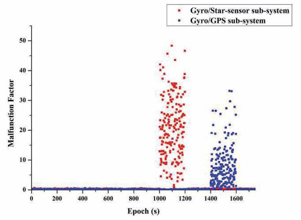
Assume that from 1000s to 1200s, the star-sensor is in
fault, with malfunctioned observation accuracy at 10 times worse than usual. From 1400s to 1600s, the GPS runs out at the same level. The attitude determination accuracy of FKF and the two subsystem filters are described in Fig. 5.
Clearly, FKF is influenced drastically when the star-sensor malfunctions, because the FKF considers the star-sensor as normal accuracy, and does not adapt its weight. However, in this period, it still performs better than the malfunctioned Gyros/Star-sensor subsystem, indicating that the Gyros/GPS subsystem works effectively, to calibrate the FKF. When the GPS is in malfunction, the FKF is hardly being interrupted, because it occupies a slight weight in the FKF. As a whole, the FKF has a good malfunction tolerance performance. Table 3 describes the statistical results.
To check the performance of malfunction-modified procedure, another simulation with the same malfunction condition is analyzed. The varying trend of malfunction warning factors in this simulation circumstance is described in Fig. 6.
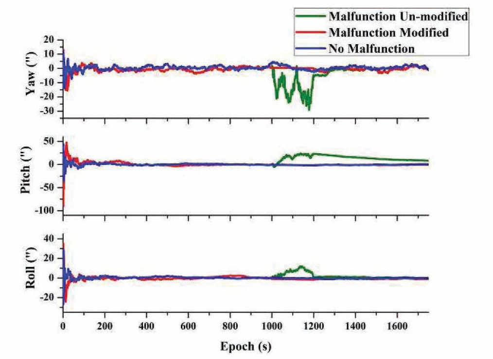
Obviously, the malfunction warning factors alarm all malfunction periods precisely and correctly. Adding malfunction tolerant design to the FKF, the attitude determination accuracy compared with no-malfunction FKF, and malfunction un-modified FKF, is described in Fig. 7.
[Table 2.] Statistical result of Euler attitude (1800s, STD)
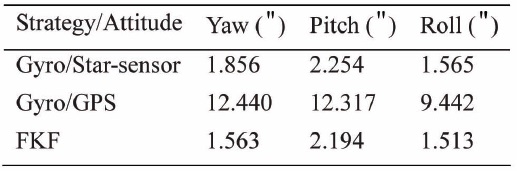
Statistical result of Euler attitude (1800s, STD)
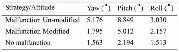
It can be seen from Fig. 7 that the FKF with the modified malfunction procedure achieves better accuracy than the un-modified one. The statistical results are described in Table 4.
Clearly, after being modified by the strategy proposed in this paper, the FKF’s final attitude determination accuracy approximately approaches the no-malfunction situation. This indicates that the strategy effectively avoids the impact of malfunction.
In this paper, an attitude determination strategy for spacecraft based on the information fusion of Gyros/ GPS/Star-sensor was demonstrated. In the information fusion process, two subsystem Kalman filters were firstly established. To cope with the problem of the different sensors’ update rates, they were both designed with variable step size state prediction strategies. Finally, an FKF with malfunction warning design was established; the output of the subsystem filters’ state and error covariance matrix were selected as the input of the main filter. The final result indicated that the FKF effectively negated the impact of possible malfunction.
This paper analyzed these problems based on the numerical simulation process; however, it did not take into consideration a sophisticated model of each sensor, and the simulation circumstance was of relatively ideal quality.
[Table 3.] Statistical result of the Euler attitude (1800s, STD)
Statistical result of the Euler attitude (1800s, STD)
In real applications, the pre-processing of real space-borne sensor data is another important problem. Besides, the FKF designed in this paper could not consistently obtain optimal estimation. These issues should be paid attention to in future research.
[Table 4.] Statistical result of the Euler attitude (1800s, STD)

Statistical result of the Euler attitude (1800s, STD)