Human spaceflight has demonstrated expertise in conducting EVAs in two distinct environments: in the microgravity of space, and on the surface of the Moon. A simple argument could be made, however, for the applicability of lunar EVA knowledge to the surface of other terrestrial bodies with gravitation similar to that of the Earth or the Moon. Mars, for example, has a gravitational acceleration at the surface of about one-third of an Earth g, more than double that of the Moon (one-sixth of an Earth g). Operational concepts utilized for lunar EVA are very relevant for Mars. However, low-gravity small body exploration, including comets, asteroids, and the moons of Mars, is a new regime, in many ways more similar to the on-orbit microgravity environment than the lunar surface environment for EVA.
The construction of the International Space Station (ISS) in microgravity was possible only because of the operational considerations included in the design. Translation about the ISS would not have been practical without numerous handrails along translation paths, and assembly would not have been possible without body restraints such as footplates and the Space Station Remote Manipulator System (SSRMS). Without restraint systems, astronauts would have had no way to react the loads induced, for example, from bolting together truss segments.
The exploration of a low-gravity body, in contrast, presents nearly all the challenges of microgravity EVA, but without the man-made utilities that made ISS construction possible. In addition, the EVA tasks of the Apollo program that were relatively simple to perform on the Moon ? taking core samples, retrieving surface samples, and even walking ? become complicated on the surface of a very low-gravity body. Thus, while the current EVA core competencies provide an excellent starting point for the exploration of very low-gravity bodies, it is apparent that both operational concepts and hardware will need to be developed to explore the low-gravity bodies that represent the next destinations for human exploration beyond the Earth-Moon system.
This paper addresses the dynamics associated with EVA on the surface of a low-gravity body. In Section 2, characteristics of candidate targets for future human exploration are discussed, and a small body is selected as the target context for this analysis. Section 3 provides general insight into astronaut mobility in a low-gravity environment, and gives geometric and load force information that is used in the subsequent sections. Section 4 describes the dynamics of small body surface EVA. An approach for lateral mobility without reliance on a propulsive mobility unit is examined. Section 5 discusses the utilization of the ISS as a research facility for developing operational concepts, tools and techniques for accomplishing low-gravity surface EVA. Conclusions are drawn, and future work is discussed in Section 6.
The intent of this paper is to highlight challenges associated with small body surface EVA, in order to motivate the development of the core competencies that will be needed for future human exploration. Like the lunar excursions of Apollo 11, the first EVA onto the surface of a body beyond the Earth-Moon system will be one of humanity’s crowning achievements. Through adaptation of current EVA approaches, and validation of new tools and techniques utilizing the microgravity environment of the ISS, the skills needed to safely accomplish small body EVA are within reach.
NASA’s Near Earth Object (NEO) Program has catalogued over 7,000 objects, with approximately 800 having a diameter larger than one kilometer, as shown in Figure 1 [12]. It has been suggested that the NEO population alone likely
approaches 100,000 individual objects [10]. The largest, 1036 Ganymed, has a diameter of 31.66 km [13], and it is significantly larger than the next largest NEO, 433 Eros, which has a mean diameter of 16.84 km [13].
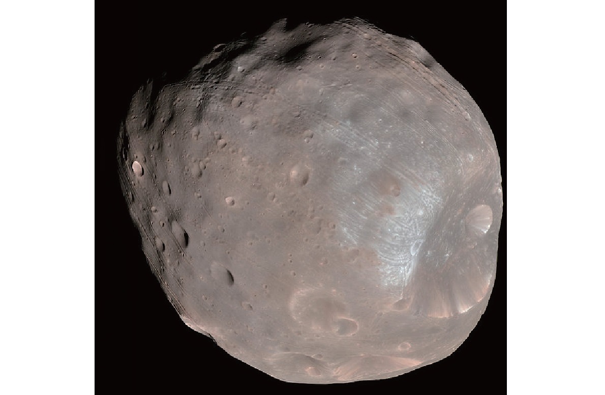
Candidate targets for human exploration may be selected based upon size, composition, rotation rate, or proximity to Earth. The broad variety of characteristics within the small body population makes it difficult to select a “representative” target for mission concept development. However, with Mars as an ultimate destination for human exploration, the moons of Mars represent high-priority destinations for NASA and international partners. Phobos, the larger of the two Martian satellites, will be used as the representative low-gravity body for this paper.
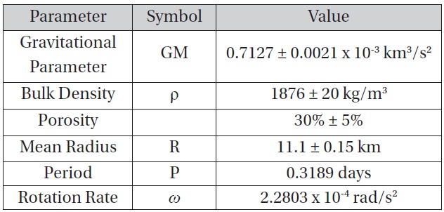
With a mean diameter of 22.2 km, Phobos is larger than all but one NEO, but it easily fits within the range of bodies that will require new EVA tactics for exploration. Additionally, there has been a considerable amount of work done to characterize Phobos: mean diameter, rotation rate, and bulk density are all measured quantities. Figure 1 is an image of Phobos taken from NASA’s Mars Reconnaissance Orbiter on March 23, 2008 [6]. To simplify the analysis of EVA dynamics, this paper will model Phobos as a sphere with constant bulk density, rotating about a single axis. Table 1 presents the parameters of Phobos relevant for this analysis. The gravitational acceleration experienced at the surface is calculated as:
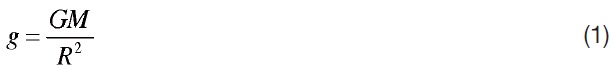
where
[Table 1.] Phobos physical properties

Phobos physical properties
acting along the radial vector. When centripetal acceleration is considered for non-zero rotation rates, the normal force vector equation becomes:

where ω is the rotation rate of the central body, in rad/s, δ is the latitude (measured from the equator),

is the unit vector in the radial direction, and

is the unit vector tangent to the surface in the northward direction. The greatest value for cos2δ (and thus the greatest effect that centripetal acceleration has on the normal force in the radial direction) is at the equator, δ=0. For Phobos, the radial component of the normal force at the equator is reduced by about 10 percent due to centripetal acceleration (on the surface of the Earth at the equator, centripetal acceleration reduces the effective gravitational force by 0.3 percent). For smaller bodies with higher rotation rates than Phobos, the effect can be even more significant [9].
Astronauts of the Apollo program adapted quickly to working in one-sixth of Earth’s gravity, finding it easy to develop a method of loping across the surface of the Moon. For an astronaut on the surface of a small body, translation will not be so simple. To estimate the walking speed on the surface of a body, the Froude number (
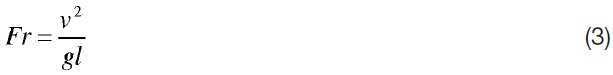
where
In light of the difficulties associated with walking in a low-gravity environment, is walking the most desirable method for mobility? If the purpose of exploring the surface of Phobos is to perform field geology and collect surface samples, then the answer is likely no. When talking about surface operations and the optimal way to work during the Apollo 11 mission debrief, Neil Armstrong said:
In general, there were a lot of times that I wanted to get down closer to the surface for one reason or another. I wanted to get my hands down to the surface to pick up something. This was one thing that restricted us more than we’d like…We should clear the suit so that you could go down to your knees, and we should work more on being able to do things on the surface with your hands. That will make our time a lot more productive, and we will be less concerned about little inadvertent things that happen. [4]
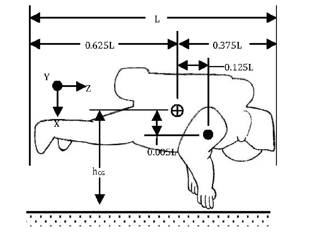
Therefore, to simplify surface exploration and to better meet the exploration objectives, a preferred body orientation may be near-horizontal within arms’ reach of the surface. The prone position affords a lower center of gravity, greater stability and a more efficient body orientation for geological sample collection. In this orientation, an astronaut would be able to propel himself across the surface of a small body with greater ease than upright walking would allow. This method of traverse would also provide less surface disturbance than propulsive transfer using a mobility unit.
To determine the motion, this paper will employ an estimated model of the Extravehicular Mobility Unit (EMU) currently used for EVA aboard the ISS. [11] Figure 2 provides an estimation of the geometry of an astronaut equipped with an EMU [15]. Note that hCG represents the height of the CG above the surface. Table 2 provides typical values for the measurements annotated in Figure 2, along with a measurement for the estimated length of a fully-extended arm. For the purposes of this analysis, it is assumed that the mass (
Finally, to be able to examine the translational and rotational motion of the spacesuit on a small body, it is necessary to know how much force an astronaut is capable of imparting. Per NASA’s Man-Systems Integration Standards, the forces that a free-floating crewmember (one not held rigidly in place by a restraint) can impart are shown in Table 3 [3].
[Table 2.] Astronaut center of gravity geometry
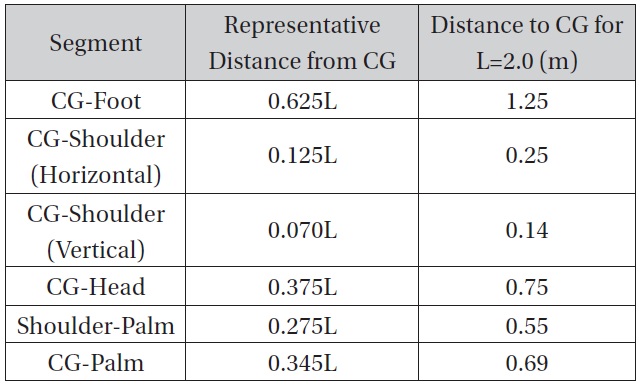
Astronaut center of gravity geometry
While the Phobos of gravity will allow greater forces to be imparted by an unrestrained astronaut, this evaluation will remain within the guidelines provided for a microgravity environment in Table 3.
4. Translational/Rotational Motion Analysis
The motion of the astronaut in response to a force imparted to the surface is calculated in two parts. First, while the astronaut is applying the force normal to the surface, the linear and angular accelerations due to the applied force can be calculated. Then, when the crewmember is in freeflight (with the only external force being due to gravity), translational and rotational motions can be determined. To calculate the motion, the astronaut is represented as a rigid body.
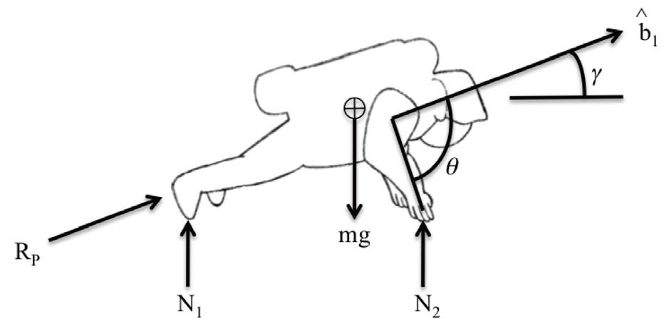
Figure 3 shows the free-body diagram of the forces acting on the astronaut. We consider astronaut motion in response to a push-off force generated by the legs, and directed along the astronaut body axis

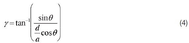
The reactive force to the push-off is labeled RP in Figure 3. Normal forces N1 and N2 combine to provide the radial component of the normal force given in Equation 2. The arm angle with respect to

is defined as
with respect to the local horizontal is
A push-off force of 20 N applied in the
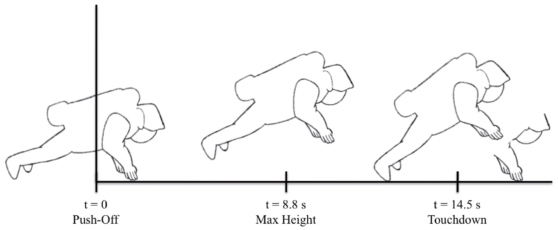
direction for 2 sec is modeled, and the resulting motion is evaluated. This pushoff force and duration is within the conservative limits for a microgravity environment defined in Table 3. The vertical component of the 20 N force is adequate to overcome the effective gravitational force, generating an upward acceleration. At the completion of push-off, the astronaut will have a horizontal velocity component of 0.155 m/s, and a vertical velocity component of 0.051 m/s. Due to the mass distribution of the EMU, the c.g. of the astronaut is offset behind the body axis, so the applied push-off force generates a torque that results in a counter-clockwise rotation. A 1 cm c.g. offset is modeled. The induced angular velocity at the completion of push-off is 0.008 rad/s.
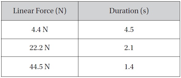
Maximum forces and duration that can be imparted by an unrestrained astronaut in a micro-gravity environment
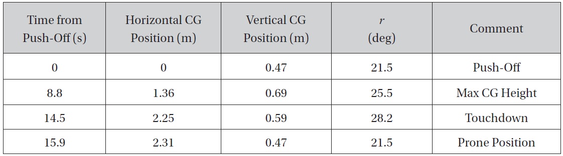
The resulting motion is illustrated in Figure 4 (not to scale). The duration of the astronaut trajectory from push-off to touchdown is 14.5 s. At push-off, the astronaut c.g. is 46.8 cm above the surface. At the maximum altitude point in the trajectory, the c.g. is 69.0 cm above the surface. The counterclockwise rotation increases
A drawback to this method of traverse is that the astronaut’s field of view is limited, relative to upright walking. Scanning the local area for candidate samples and geologic sites of interest will be difficult in the prone position. A headsup display on the astronaut’s visor could allow regional information to be presented to the astronaut based upon remote sensing imaging acquired from orbit.
[Table 4.] Trajectory profile during traverse

Trajectory profile during traverse
5. ISS Utilization for EVA Research
Hardware and operational concept development for a low-gravity exploration program would be well served to employ a progressive approach, utilizing available resources to test the devices and techniques that will be needed to both keep astronauts safe and allow them to be productive. NASA has a number of existing assets for EVA development and testing, including the Neutral Buoyancy Laboratory and the Virtual-Reality Laboratory, both of which are housed at NASA’s Johnson Space Center. Each facility, however, will have benefits and deficiencies with respect to very lowgravity exploration development.
The zero-gravity aircraft that NASA utilizes to test and validate concepts and hardware, for example, are capable of parabolic flight paths that can imitate roughly any gravitational force, from microgravity to lunar gravitation and beyond. The parabolas, however, only yield continuous test-time on the order of 30 seconds. Additionally, since the inside of an aircraft is a confined environment, it is not an ideal setting to test large scale, long-duration motion response hardware. NASA understood these limitations when it addressed the design and validation of the SAFER. Built as a self-rescue device for an astronaut that becomes inadvertently separated from the spacecraft during an EVA, SAFER uses cold-gas nitrogen thrusters to provide attitude control and propulsion. Instead of attempting to validate its design in a simulated environment, NASA chose to test it in low-Earth orbit as part of a Designated Test Objective (DTO). Flying on STS-64 in 1994, STS-88 in 1998 and STS-92 in 2000 [2], the SAFER was used during an EVA on each flight, to improve the design and validate it as a redundant safety system. In a similar manner, very low-gravity EVA hardware and operational concepts can and should be tested through a series of EVAs conducted onboard the International Space Station.
5.1 Driving Questions for an ISS-Based EVA Test Program
Throughout the history of human spaceflight, astronauts have demonstrated a high level of adaptability for working in the EVA environment; some of the perceived challenges regarding very low-gravity EVA may be less significant if astronauts can minimize the severity of those challenges simply through adaptation. An ISS-based test program can provide flight data and experience that is directly relevant to low-gravity surface EVAs. The test objectives should be progressive, and the program schedule should be constructed such that the lessons learned from each test can be used to update the objectives and hardware for subsequent testing. In this way, the ISS becomes a test-bed for low-gravity EVA research.
A number of basic questions need to be answered to define the EVA research program. This paper has focused on surface mobility, because it is a necessary core competency for very low-gravity body exploration. If an astronaut cannot safely and efficiently move about on the surface of a very low-gravity body, science return from human exploration missions will be limited. Geological exploration is most valuable when the samples are collected within the geological context of the body. “As a field geologist works
to develop an understanding of an area of geologic interest, they look to all the data available for the site and execute multiple field excursions to both map and collect samples.” [14] An operational concept that restricts astronauts to an isolated area within reach from the landed spacecraft would be severely limiting. Every effort should be made to provide astronauts with surface mobility.
The following are some of the questions regarding surface mobility that may be answered through an ISS-based EVA research program:
What is the minimum level of gravitation within which an astronaut can safely and effectively operate without a restraint system (no tethers, handholds, or anchors of any kind)?
How well can an astronaut adapt to using only the minimum amount of force needed to maneuver about on a low-gravity body?
How well can an astronaut learn to direct the applied forces to limit vertical linear motion without the aid of an attitude control system?
How well can an astronaut absorb and dissipate the translational and rotational energy, to avoid uncontrolled motion?
What is the optimal way to design a spacesuit and ancillary hardware that allows an astronaut to remain in the prone position without the majority of spacesuit touching the surface (e.g., bi-pods on the feet, braces extending from the spacesuit chest, etc.)?
Can the spacesuit be designed to assist in controlling rotation, while protecting the pressurized volume from cuts and tears due to abrasion?
What are the minimum requirements for an attitude control system utilized in surface EVA?
Would a helmet-based visualization system (i.e., a
heads-up display) aid in mobility and spatial awareness?
From the previous analyses, the motion of an astronaut on the surface of a low-gravity body has the potential to be hazardous. Through obtaining experimental and empirical data, operational concepts and spacesuit designs can be advanced in order to reduce the risk of EVA.
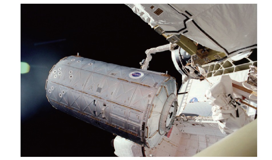
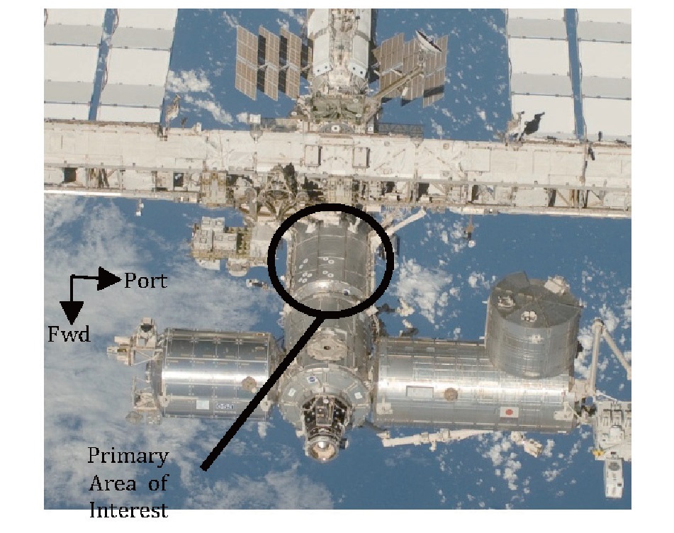
The zenith side of the U.S. Destiny Laboratory may be a feasible location to perform a series of EVA-based tests. The Lab itself is about 8.5 meters long, with a diameter of 4.4 meters [2]. Figure 5 shows the Laboratory as it was being installed during STS-98, in 2001 [7]. Figure 6 shows a flyaround photo taken during STS-127, in 2009 [5]. In the region on the Lab noted as the primary area of interest in Figure 6, two rows of handrails run aft from the forward end-cone. In this location, an astronaut could use a system of slide wires and cables to evaluate many of the topics discussed in Section 5.1.
Knowing the basic dimensions of the module, it can be estimated from Figures 5 and 6 that the handrail rows are about 1.3 meters apart. Additionally, the distance from the forward end-cone to the point where the S0 truss segment attaches to the Lab is about 4.85 meters.
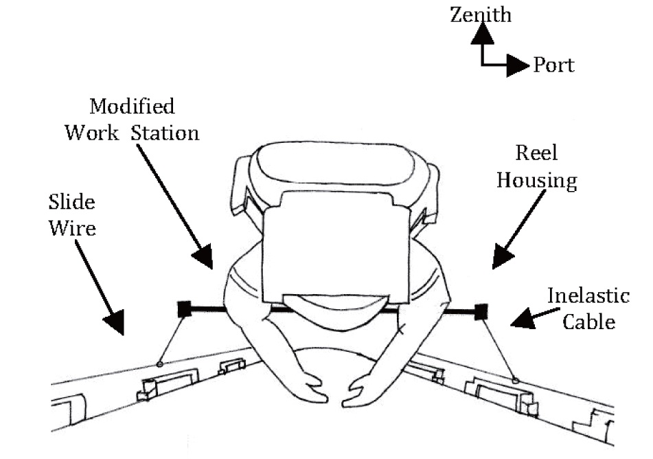
To begin, an astronaut would install a slide wire stanchion onto the end of each handrail row, running forward and aft. This would allow two separate, parallel slide wires to run from the forward end cone to a handrail stanchion near the location where the S0 truss segment attaches to the Laboratory, an overall length of approximately 4.85 meters. Then, an astronaut would employ a modified work station that attaches to the front of the EMU. This work station has two armatures, each with a reel housing at the end of it. Within each reel housing an inelastic cable is connected
to a constant-force spring. The astronaut positions himself between the slide wires, and attaches each inelastic cable to the respective slide wire by a small hook at the end of the inelastic cable. Figure 7 shows the astronaut between the slide wires, with the inelastic cables attached. By varying the spring force, it is possible to mimic any desired gravitational acceleration. Translational and rotational dynamics can be assessed using such a system, and work scenarios may be evaluated. Additionally, altering the force of the constantforce spring system will provide astronauts an opportunity to evaluate the need for a restraint system, as a function of simulated gravitational acceleration. This assessment alone will be highly valuable, as it may be used to rule out potential targets if no restraint system is desired.
As testing progresses, this apparatus can be used to test various damping systems, attitude control systems, and eventually spacesuits designed for low-gravity EVA. It is also likely that engineers and astronaut training specialists can devise additional ways to configure worksites aboard ISS to cater to this type of testing. In this way, ISS can be an unparalleled research facility that paves the way for the future exploration of the solar system.
The challenges over the next two decades for human space exploration will revolve around our ability to work in low-gravity environments. EVA on asteroids, comets, and the moons of Mars will likely prove to be even more challenging than those on the lunar surface or in the microgravity of low-Earth orbit. Within the gravitational environment of Phobos, walking on the surface without a restraint system will be prohibitively slow. Physical activities associated with geological field techniques will be hindered by the lack of a gravitational field strong enough to oppose the forces applied in collecting samples. The centripetal acceleration due to rotation of the central body is a significant effect that acts counter to gravitational acceleration. For small bodies with high rotation rates, EVA without a restraint system or EMU may not be viable.
Unassisted traverse of an astronaut on the surface of the small body may be accomplished more efficiently from a prone position than in an upright walking posture. For Phobos, unassisted traverse rates of 0.13 m/s can safely be achieved from the prone position. This motion is similar to that of bouncing along the bottom of a swimming pool, in near-neutral buoyancy. With training, the technique of traversing in the prone position would become natural to astronauts.
The International Space Station can be utilized as a proving ground for low-gravity surface EVA tools and techniques. A system of slide wires and cables could be fitted to the U.S. Destiny Laboratory to enable the simulation of low-gravity EVA scenarios. A progressive surface EVA test program at the ISS can resolve questions related to surface EVA mobility, safety, spacesuit design, restraint systems, EMU design, and visualization aids.
As the vehicle development for human exploration beyond the Earth-Moon system progresses, it is critical to advance the tools, techniques, and operational concepts associated with EVA at the likely destinations. Through addressing the challenges of low-gravity surface EVA early in the mission concept phase, operational risks may be reduced, and the successful heritage of EVA can be extended to small bodies throughout the solar system.


![ISS Destiny Laboratory during install, STS-98[7]](http://oak.go.kr/repository/journal/12070/HGJHC0_2013_v14n1_11_f005.jpg)
![ISS Destiny Laboratory, STS-127 fly-around[5]](http://oak.go.kr/repository/journal/12070/HGJHC0_2013_v14n1_11_f006.jpg)