With the rapid development of low-power wireless sensor networks and the micro electromechanical system (MEMS), efficiently supplying power has become an important engineering problem. While batteries have historically been used, they have a number of disadvantages, such as short lifetime, a finite amount of chemical energy, difficult to replace and recharge, and cause critical environmental pollution. Therefore, renewable power supplies need to be discovered as a substitute for chemical batteries.
Energy harvesting from ambient vibrations has become possible over the last few decades [1,2], and is an attractive source due to its unlimited operating time and unrestricted location. The techniques for vibration energy conversion are piezoelectric [3,4], electrostatic [5,6], and electromagnetic [7,8]. The energy levels obtained using these techniques are sufficient for powering various types of microsystems such as data transmission and sensor nodes. While piezoelectric conversion has high output voltage, most of the high coefficient piezoelectric materials are toxic and brittle. The electrostatic conversion can be regarded as a variable capacitor. It can be fabricated for MEMS applications, but requires an isolated voltage source. On the other hand, the electromagnetic conversion offers high power efficiency and low frequency due to the simple mechanical resonator structure of the device. However, the device size is limited and generates low level output voltage.
In the literature, electromagnetic power scavengers have been investigated, including the moving magnet type and moving coil type. An energy harvester generates maximum power when the environmental frequency matches the resonance frequency of the device, but environmental vibrations are typically below 10 Hz and have broadband characteristics. There is a need for energy scavengers that operate at low and broadband frequencies.
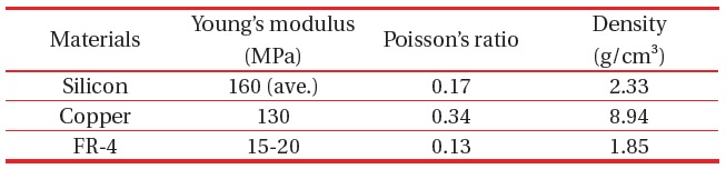
A majority of the vibration driven EMEH suse the silicon or copper springs. The spring material has an effect on the resonance frequency of the system. The FR-4 material has specific mechanical properties (Young’s modulus, Poisson’s ratio, and Density), low cost, and simple processing compared with silicon and copper.
In this paper, we propose a FR-4 spring based electromagnetic energy harvester for low frequency. The mechanical characteristics of the spring mass system were analyzed and simulated by using mathematical modeling and FEA. The characteristics of EMEH are shown in the experimental results, which consist of output voltage and power with input frequencies acceleration, and load resistance.
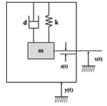
The dynamic behavior of the generator is described using a novel bidirectional coupled segmented analytical model assuming a damped harmonic oscillator with proof mass that is excited by external acceleration as shown in Fig. 1.
We use steady state analysis to determine and predict the practical performance of the device. The harvester consists of a seismic mass (
The dynamic equation of the mass spring damper system can be written as

where {

Therefore, equation 1 can be written as

or

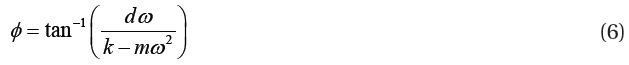
The term on the right hand side of the above equation defines the force applied to the system, and the terms on the left hand side describes the relative motion between the mass and the generator housing. If the displacement of housing

where
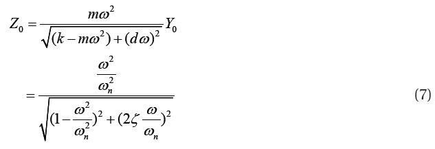
where
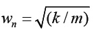
is the natural frequency, and
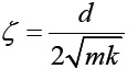
is the damping ratio of the seismic suspension.
The mechanical power of the spring mass system can be defined as
The total force is due to the spring force and damping force. Therefore, the power can be determined as

By replacing

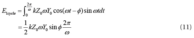
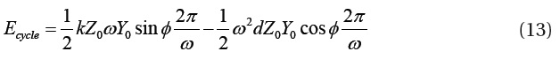
The energy transferred during one complete cycle of vibration is

where,
and
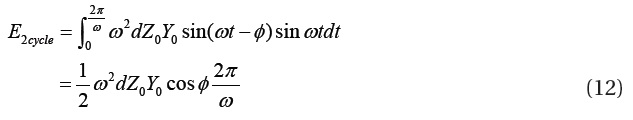
Combining equations 10, 11, and 12, the total energy during one cycle can be achieved as
The average power can be estimated by
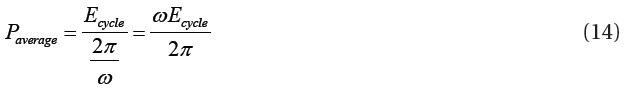
Taking total energy into consideration, average power can also be expressed as
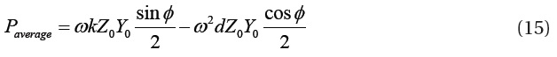
Incorporating the vibration amplitude of the mass into equation 15 gives the average power delivered to the electrical domain
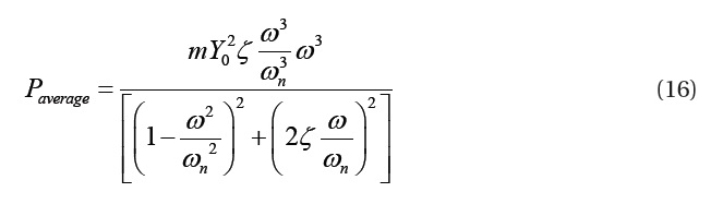
The main conclusion of this mathematical analysis is that the amount of power generated is proportional to the cube of the vibration frequency. This means that the generator will produce much more power in applications where there is a fairly high frequency of vibration and will produce low power at low frequency. However, in reality, the acceleration level is not constant with input frequency. Commonly, the vibrations occurring at high frequency have lower acceleration, and low frequency has higher acceleration.
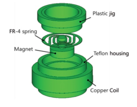
A schematic diagram of EMEH based on a FR-4 spring is shown in Fig. 2. The energy harvester is composed of an active spring mass system, a plastic jig, and cylindrical Teflon housing with a copper coil. The active spring mass system consists of a FR-4 planar spring and vertically polarized NdFeB (N35) permanent magnets.
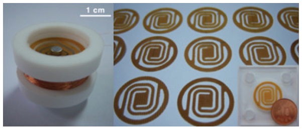
The fabricated low frequency driven EMEH and FR-4 spring is shown in Fig. 3. A copper coil was wound at the center of the housing and the jig was located at the top of the housing to fix the spring mass system. The fabricated EMEH has a 21cm3 volume and a 30 g mass.
The FR-4 spring was designed as a curve type beam structure to reduce the stress and frequency. FR-4 is the most commonly used material as an electrical insulator due to its considerable mechanical strength. The FR-4 spring was fabricated by a desk computer numerical control (CNC) 3D modeling machine. CNC machines can be used continuously 24 hours a day and are programmed with a design which can then be manufactured hundreds or even thousands of times. Each manufactured product will be exactly the same, thus itsaves time and cost compared with semiconductor and laser processing [9,10]. The permanent magnets are attached to the center of the spring which is 1 mm width, 200 μm thickness, and has a 1 mm gap.
The mechanical characteristics of the spring mass system are simulated by using FEA. The model analysis was performed to predict the resonance frequencies and mode shapes of the spring mass system.
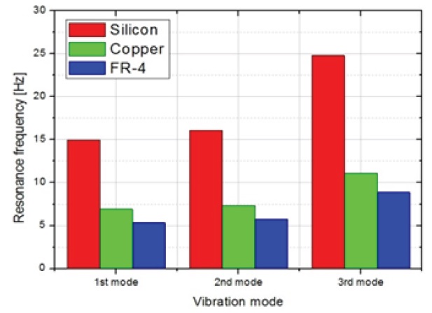
Figure 4 shows the variation of the three lowest resonance frequencies of the energy harvester with materials of the spring: silicon (red), copper (green), and FR-4 (blue). In order to determine the spring material, we need to consider the resonance frequency range of low resonance modes. In the FR-4 spring, the EMEH has the lowest resonant frequencies of all resonance modes due to the specific mechanical properties (Table 1). In addition, when we use a spring with a longer and thinner beam or a magnet with a heavier mass of magnet, we will be able to drop the resonance frequency consistently.
Figure 5 shows the three lowest vibration modes with the FR-4 spring. It can be seen that the first and second modes are torsional at 5.374 Hz and 5.799 Hz, respectively, and the third mode
[Table 1.] Properties of spring materials.

Properties of spring materials.
is the out of plane mode at 8.363 Hz. Hence, vertical deflection of the magnet can be achieved at the third resonance. In the third mode, the spring mass system moves the vertical direction with the maximum deflection (z-axis).
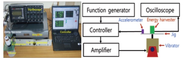
The experimental setup for testing the proposed device is shown in Fig. 6. The energy harvester was placed on the platform of a jig. A function generator (SCO-01P), controller (LAS-200), amplifier (PA25E-CE), accelerometer (IEPE-8341) and vibrator (LDS-V201-M4) were used to make the signal and control the vibration strength. An oscilloscope (LeCroy) is connected to the harvester coil in order to measure the induced output voltage with different frequencies, accelerations, and load resistances.
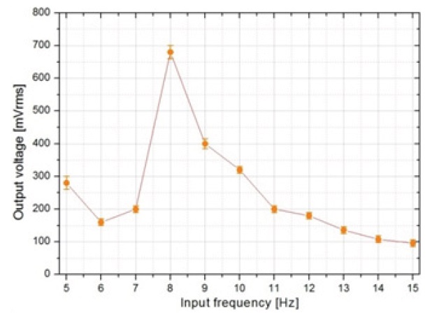
Figure 7 shows the variation of output voltage with the input
frequency. The induced output voltage depends strongly on the external vibration frequency. The maximum output voltage is generated in the resonant frequency, and drops significantly out of the frequency range. With the acceleration of 0.2 g in the frequency range of 5-15 Hz, the fabricated FR-4 spring based EMEH generates the maximum voltage of 680 mV at 8 Hz.
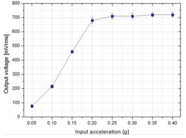
The output voltage acceleration response of the device is shown in Fig. 8. The induced output voltages increased as the acceleration increased because the displacement of the vibrator depends on the frequency and the acceleration. Therefore, the increased acceleration of the vibrator with a resonance frequency (8 Hz) resulted in greater displacement of the system. As a result, when the acceleration of the vibrator increased, the system exhibited linear and nonlinear behaviors. This demonstrated the linear and nonlinear behaviors at low and high frequencies, respectively. The output voltage will be saturated with the increased acceleration. We can expect the maximum output
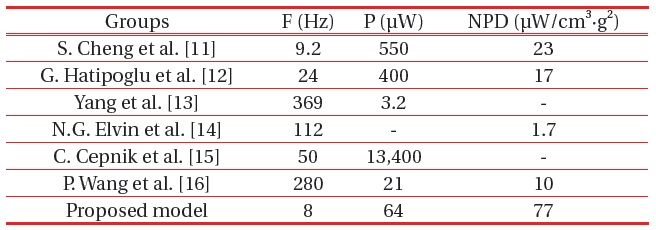
[Table 2.] Characteristics of previously reported EMEH.

Characteristics of previously reported EMEH.
voltage of around 720 mV from the saturated value.
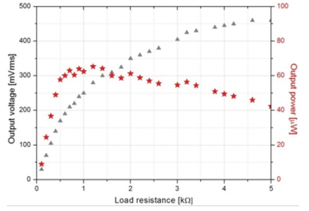
Figure 9 shows the results of output voltage and power with the load resistance. The induced voltage increases with the load resistance, and the maximum output power is 65.33 μW at a load resistance of 1.2 kΩ from 0.2 g acceleration at a resonance frequency of 8 Hz.
Table 2 shows a critical comparison of the proposed EMEH
with previously reported devices. The Normalized Power Density (NPD) was used to evaluate the efficiency of the system and the proposed model has a superior NPD (77 μW/cm3·g2 @ 8 Hz) and frequency compared with other research groups.
We have demonstrated low frequency driven EMEH using the FR-4 spring system. The proposed energy harvester consists of NdFeB permanent magnets, an FR-4 planar spring, and a cylindrical- type copper coil. The released device generated a maximum output power of 65.33 μW against a load resistance of 1.2 kΩ at a resonance frequency of 8 Hz while the acceleration was 0.2 g. Compared to the previously reported low frequency driven energy harvesters, our prototype can generate a higher NPD (77 μW/cm3·g2) at lower frequency (8 Hz).
From our results, we conclude that the proposed EMEH is suitable to harvest power at a low frequency level. Further research is needed regarding efficient power processing, energy storage, and reliability.