In order to apply YBCO thin-film wires to superconducting electric power equipment, various factors need to be investigated. These factors include the phase change on the quenching characteristic (the resistance increase tendency) that is converted from the superconducting state to the phase transition state, and the phase change on the quenching characteristic (the recovery tendency) that is returned from the phase transition state to the superconducting state. Because insulating layers are required for the application of YBCO thin-film wire to superconducting electric power equipment, an investigation needs to be carried out on the phase change characteristic.
In this study, the resistance and recovery properties of the YBCO thin-film wire are analyzed based on the presence and thickness of the insulating layer and the kinds of stabilization layers [1,2] at 90 K, 180 K, and 250 K. This study further examined the YBCO thin-film wires with different stabilizing layers and insulating layers in terms of their various characteristics. Examples of such characteristics include quenching occurrence, spread, and distribution based on their resistance increase trends and their recovery from
[Table 1.] Properties of CCs & insulation layer.
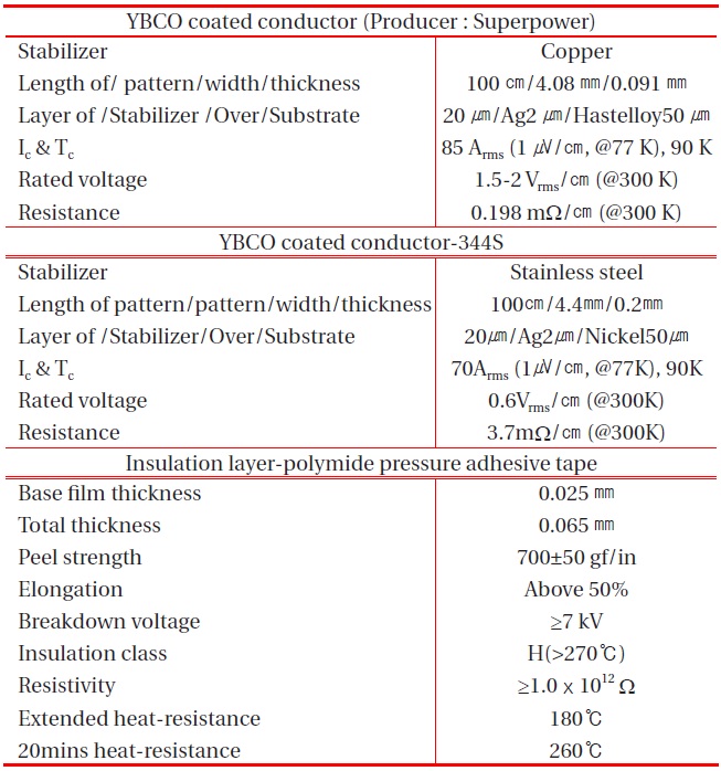
Properties of CCs & insulation layer.
quenching. The results were qualitatively explained. Furthermore, the result from this study on the characteristics superconducting and normal conducting phase changes of YBCO thin-film wires are expected to be useful in designing superconducting power machines and in improving their performance [3,4].
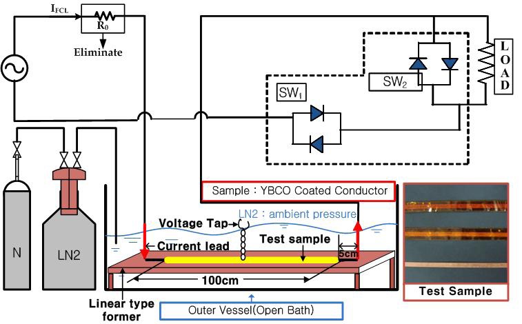
Six types of test samples were wound on a straight-type frame. These samples were wrapped with one layer, three layers, and five layers using two types of wires and insulating materials of the same characteristics (see Table 1). Two test sample types were not covered with insulating layers. The polyimide pressure-sensitive adhesive tape, which exhibits superior performance at very low temperatures, was used as the insulating layer. The insulating layer was 0.065-mm thick, attached to the front and rear of the wire to stop the penetration of liquid nitrogen. These prepared test samples were applied to the fault current within 6.5 cycles, after they were connected to the application device of the fault current (see Fig. 1).
Calculations were performed of the resistance and temperature generated in the wires. The recovery time was measured using the fault current and voltage after quenching was detected in the samples at that time. The fault current was applied to the line by closing Sw2 in the diagram. In particular, the R0 resistor, which was installed ahead of the current-limiting element, was removed, while the fault current flowed in the line using only the Z percentage of the power. For the current-limiting element with a copper stabilizing layer, the following values required the resistance values corresponding to 90 K, 180 K, and 250 K: 354 Apeak
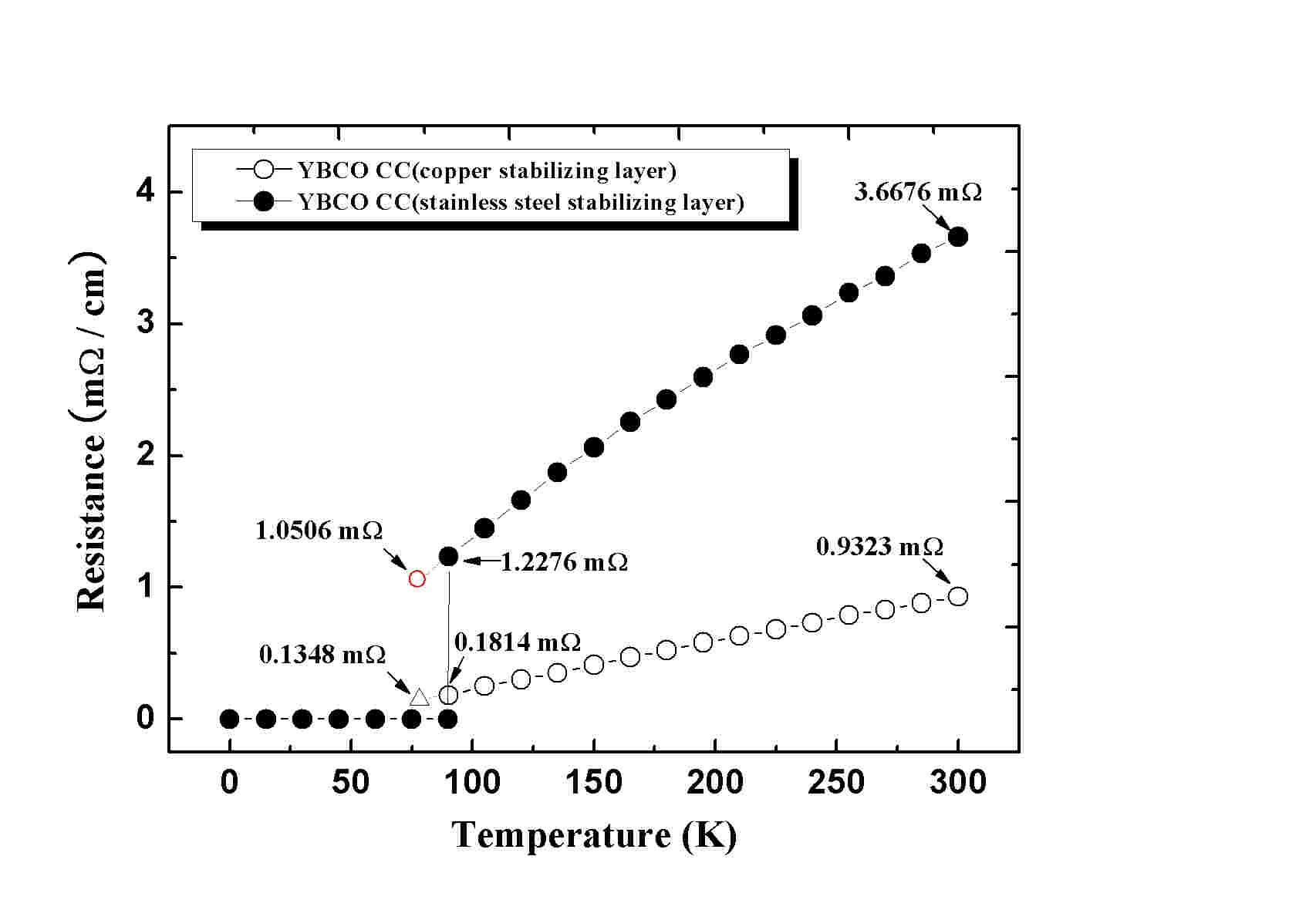
at 10 Vrms, 517 Apeak at 20 Vrms, and 712 Apeak at 25 Vrms, respectively. For the current-limiting element with a stainless-steel stabilizing layer, the current values were 517 Apeak at 15 Vrms, 915 Apeak at 25 Vrms, and 1,410 Apeak at 35 Vrms. Figure 2 shows the resistance curve depending on the temperature of the two types of wires. The graph in the figure represents the basic value needed to assume the generated temperature in the wires that corresponded to the generated resistance value in the wires [5].
This chapter considers the thickness of the insulating layers and stabilization layers that have influenced the tendency and recovery characteristics of the resistance increase. The temperatures are noted at 90 K (critical temperature), 180 K (moderate temperature) between the critical temperature and the temperature for the complete quenching, and 250 K (the temperature for complete quenching).
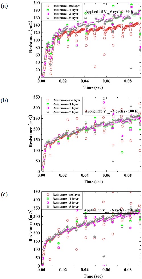
3.1 The resistance increase tendency
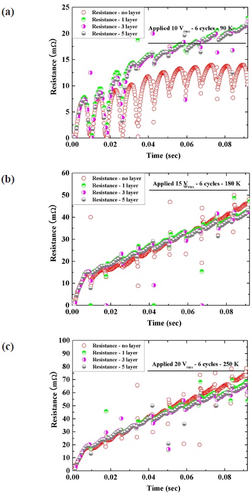
Figures 3 and 4 show the influence according to the presence of the insulating layers that occurred at around 90 K. Almost the same resistance increase tendency appeared at the other temperatures. The results confirmed that the analysis of the resistance increase tendency depended on the material of the
stabilization layers. The thickness of the insulating layer containing stainless steel influenced the resistance increase in the wires. This was due to the difference in the specific resistance values of the stabilization layers. As a result, it was verified that the test wires had different resistance increases according to the materials of their stabilization layers. Generally, however, the influence of the insulating layers was significant around the critical temperature of 90 K. As a temperature of around 250 K (for complete quenching) influence was less significant.
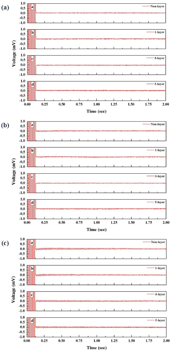
3.2 The recovery characteristics of the superconducting state
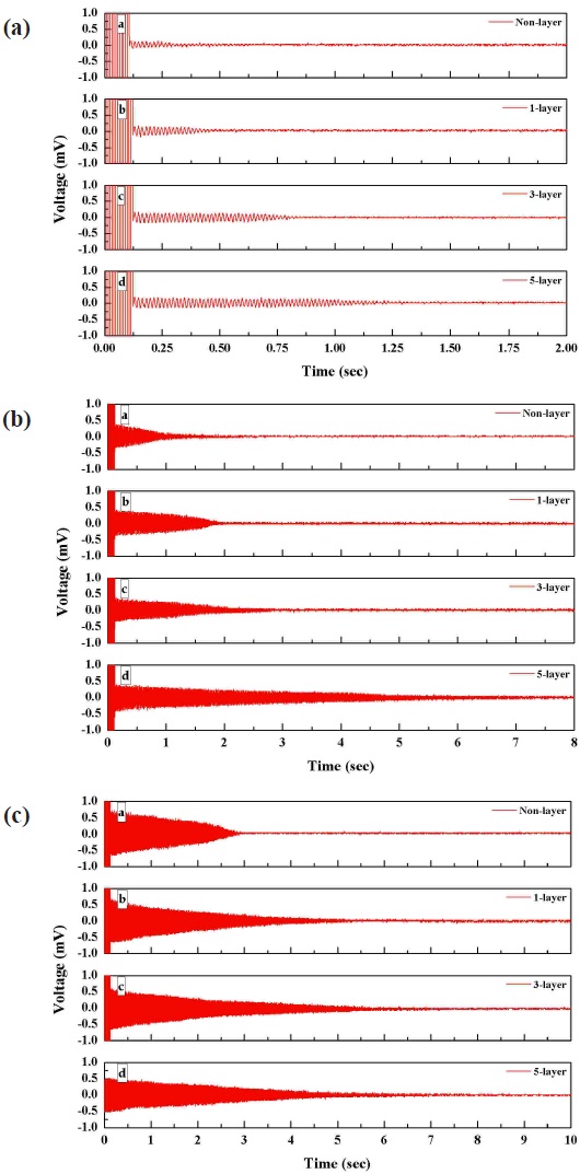
The results (see Figs. 5 and 6), for which the recovery characteristics were considered, show that the influence according to the properties of the material in the stabilization layers and the thickness of the insulating layers significantly differed from the resistance increase tendency, as mentioned earlier. The stainless steel wire in the stabilization layers needed a longer recovery time than the copper wire. The recovery of the superconducting state was estimated to be slower when the wire was connected to the stabilization layers with significant resistance. This was based on the increase in the thickness of the insulating layers.
In order to utilize the superconductor in electric devices, it is essential to investigate the phase transition characteristics of the superconductor with an insulating layer. This study applied an insulating layer to the YBCO thin-film wire which is expected to be useful for a superconducting electric apparatus. The phase transition characteristics of the wire after quenching were analyzed and summarized in terms of the resistance increase and its tendency to recover its superconducting state.
The resistance generated from the wire according to the presence of the insulating layer and its thickness existed only at a temperature of around 90 K at which the quenching occurs. This indicates that the insulating layer only influenced the initial small-scale heat accumulation of the wire. This characteristic increased and accelerated the generation of resistance in the wire at the initial stage of quenching. This tendency had large variations based on the specific resistance of the stabilizer layer.
From the recovery tendency to the superconducting state after removing the fault current, the following two characteristics were found. Just after the removal of the fault current, the magnitude of the residual voltage was influenced insignificantly by the presence of the insulating layer and its thickness. However, this influenced the time required for the recovery of its superconducting state. The reason behind this is that the insulating layer influenced the small-scale heat accumulation, as in the tendency of the resistance increase. This tendency significantly varied according to the specific resistance of the stabilizer layer.
Thus, it is desirable that the thickness of the insulating layer should be minimized considering the class of the superconducting electric device.