Since their discovery in 1991, carbon nanotubes (CNTs) have attracted considerable attention from the scientific community and industry. CNTs are recognized as ideal reinforcing fillers for polymers due to their unique mechanical properties and high aspect ratio [1]. CNTs have high values of strength and modulus, of almost 200 GPa and 1 TPa, respectively [2-4]. Many studies have been devoted to the manufacture of CNTreinforced polymer composites. Nevertheless, there have been a lot of problems that have occurred from entangled CNTs in three dimensions. So, CNTs should be cut and then dispersed in a composite matrix [5-7]. One alternative from the perspective of CNT dispersions has been both short and aligned CNTs. The powder form of short and aligned CNTs can be more easily dispersed in a composite matrix than can be normally grown CNTs. Several researchers [8-14] have succeeded in growing aligned CNTs powders, but there has been no fabrication of a composite with aligned CNTs. Current materials do not seem to be suitable for composites because of the use of high temperature in the CNT growth and high molybdenum contents in the catalysts. And, there have been only a few trials to control CNT length [15,16]. In previous reports, the amounts of produced CNTs were not sufficient to carry out a composite study on CNT lengths. To determine the exact effect of CNT length on the mechanical and electrical properties of CNTreinforced composite, length controlled CNTs need to be synthesized.
The purpose of this work is to achieve the synthesis of aligned and length-controlled CNTs with high yield and product and to establish their mechanism, simultaneously.
For the synthesis of catalysts, iron nitrate, magnesium nitrate, ammonium molybdate and citric acid were all extra pure grade (SamJeong Chem., Korea) and were used without further treatment. Five different components of Fe-Mo co-catalysts in MgO support were prepared using the combustion method.
2.2. Preparing and pelletizing aligned CNTs
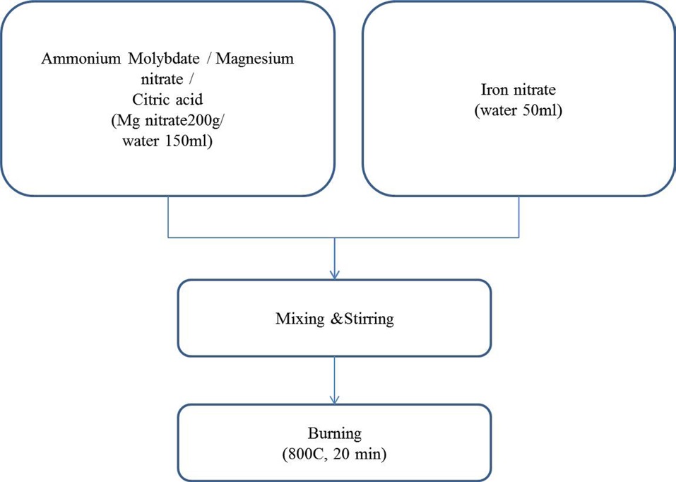
The catalyst was prepared using the combustion method. Mg(NO3)26H2O, (NH3)6Mo7O244H2O, Fe(NO3)39H2O and citric acid were dissolved in hot distilled water. Five different proportions of Fe/Mg/Mo were prepared with fixed molar ratio of Mg; we changed the ratios of Mo and Fe through a certain procedure, as follows. First, molybdenum hydrate was dissolve in pre-heated water. Then, magnesium nitrate and citric acid were added to the aqua solution, in order. And, the separately-prepared iron aqua solution was poured into the solution in which molybdenum, magnesium and citric acid were solved. Finally, the catalyst powders were obtained when the resulting solutions were burnt in air at 800℃ for 20 min. A more detailed description of the preparation of the catalyst is shown in Fig. 1. The chemical vapor deposition (CVD) reactor was heated to 650℃; then, the catalysts in amounts from 1 g to 10 g without grinding were inserted into the center in order to grow aligned CNTs. The mixture of C2H4 and H2 at a flow rate of 4000 sccm (C2H4/H2 = 3:1) was introduced into the tube. After 60 min reaction, the C2H4/H2 was shut off and the system was cooled to room temperature.
Synthesized CNT samples had different amounts of CNTs, but the samples were used without further chemical treatment. It was not easy to compound polymers with aligned CNTs, because the densities of the aligned CNTs, which ranged from 0.01 to 0.04 g/cc, were too much smaller than those of polymers. To make the pellets similar to thermoplastic polymers, all CNT samples were first ground with a mixer and simply mixed with
water (the ratio of water to CNTs was 10 to 1). Then, pelletized CNTs were made by passing the material through a home pelletizer and drying samples at 120℃ for 12 h.
The synthesized CNTs were analyzed using an scanning electron microscope (SEM) to determine the morphology of the CNT powders; using a transmission electron microscope (TEM) to determine the averages and distributions of diameters; using a Raman spectroscope to determine the crystalline properties of the CNTs; and using thermo-gravimetric analysis (TGA) to determine the purity of the CNT powders.
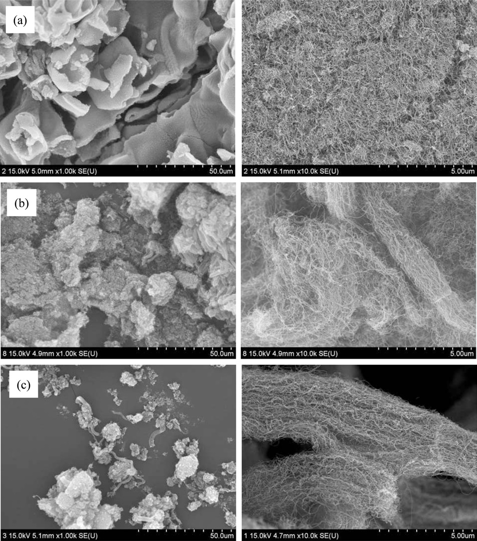
To obtain aligned CNT powders, we changed the amounts of citric acid, while maintaining fixed proportions of metal catalysts and supports, and fixed synthesis temperature of the catalysts. The ratio of citric acid to magnesium nitrate was increased in increments of 0.5 from 0.5 to 2.0. All CNTs were grown at 650℃. When the ratio reached 1.0, aligned CNTs began to appear. But, even when the ratio was 2.0, the morphologies of the samples were similar to those when the ratio was 1.0, as shown in Fig. 2. So, we changed the preparing temperature of the catalyst from 600 to 800℃. Fig. 3 provides SEM images of the as-grown CNTs with catalysts synthesized using the same ratio of metal contents to MgO supports with different synthesis temperatures. The CNTs shown in Figs. 3a-c were grown at 650℃ in an atmosphere of ethylene and hydrogen gas for 1 h using catalyst/supports synthesized at 600℃, 700℃ and 800℃, respectively. It can be seen that there were no aligned CNTs grown
on the catalysts synthesized at 600℃ at all, but a small quantity of CNTs were aligned on the catalyst at 700℃. Finally, it seems that most CNTs on the catalyst at 800℃ were well aligned in one direction. With the increase of the temperature for the preparation of the catalysts, besides the alignment of CNTs, the yields of CNTs were also increased as much as 2000, 3000 and 6000 wt%, in the order of Figs. 3a-c, as can be seen in Fig. 3. It was analogized that the amounts of metal nanoparticles compared to the grown CNTs were enriched due to the increase of the preparation temperature of the catalysts. According to the papers of Lie et al. [13] and those of several other researchers [14-16], the catalysts for aligned CNTs were calcined at a temperature of more than 750℃. Those researchers reported that the growth mechanism of the aligned CNTs grown over molybdenum/magnesium oxide or iron, nickel, and cobalt doped molybdenum/magnesium oxide catalysts, in which the absorption of hydrogen makes the molybdenum nanoparticles separate out from the inside to the outside of the catalyst, led to the formation of multilayers of molybdenum nanoparticles on the surface of the support. This explanation was not suitable for our study, because those researchers used molybdenum as a catalyst for the synthesis of aligned CNTs, and, even though they introduced iron or nickel, cobalt as catalysts, the contents of those catalysts were less than 10 molar % molybdenum. The growth mechanism of the aligned CNTs on the iron-rich catalyst or molybdenum-poor catalyst, such as were used in our study, would be similar to that of aligned growth on a substrate such as silicon wafer. This means that the metal nanoparticles such as MgO could easily melt and then move from the inside of the ceramic supports to the surface of the ceramic supports when catalysts were synthesized
at the temperature of 800℃.
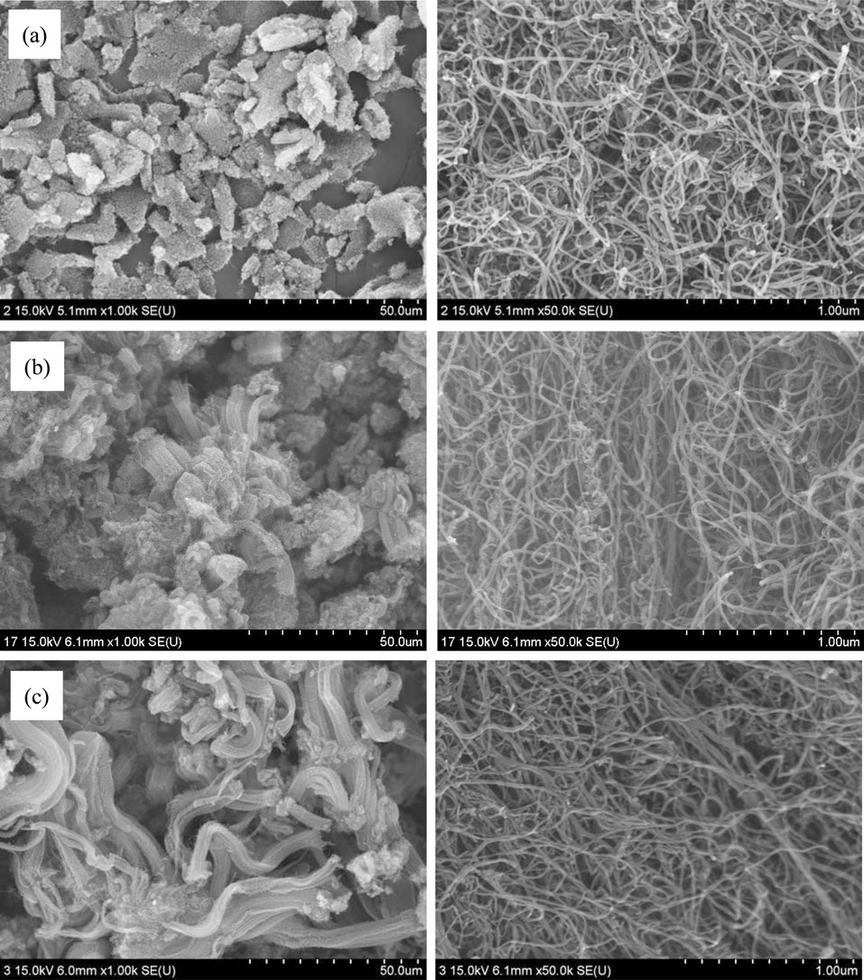
To determine the effect of the supports on the synthesis of aligned CNTs, support precursors were changed to aluminum nitrate, calcium nitrate and manganese nitrate instead of magnesium nitrate. All catalysts were combusted under the same temperature of 800℃, as previously mentioned. Fig. 4 provides SEM images of the as-grown CNTs on different supports in order of magnesium oxide, aluminum oxide, and calcium oxide. In the cases of magnesium oxide and aluminum oxide, the CNTs were synthesized with alignment, as shown in Figs. 4a and b. But in the cases of calcium oxide and manganese oxide, CNTs were not as aligned as they are for the sample shown in Fig. 4c. Even when the same portion of catalysts was used for aligned CNTs, the yields of CNTs were 6000%, 500%, 200% and 50%, respectively, in order of magnesium oxide, aluminum oxide, calcium oxide and manganese oxide. According to NFPA 704, reactivity, such as explosive decomposition, differs according to the nitrate form of support. It could be assumed that this would lead to various statuses of the catalysts, such as loading amounts on and attachment with supports, and, therefore, that the yields and alignments of the CNTs would be affected according to the types of the support materials.
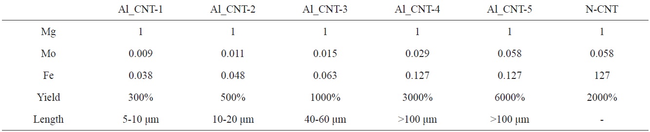
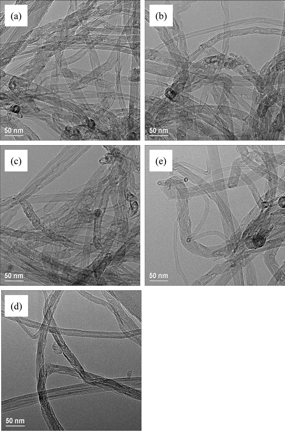
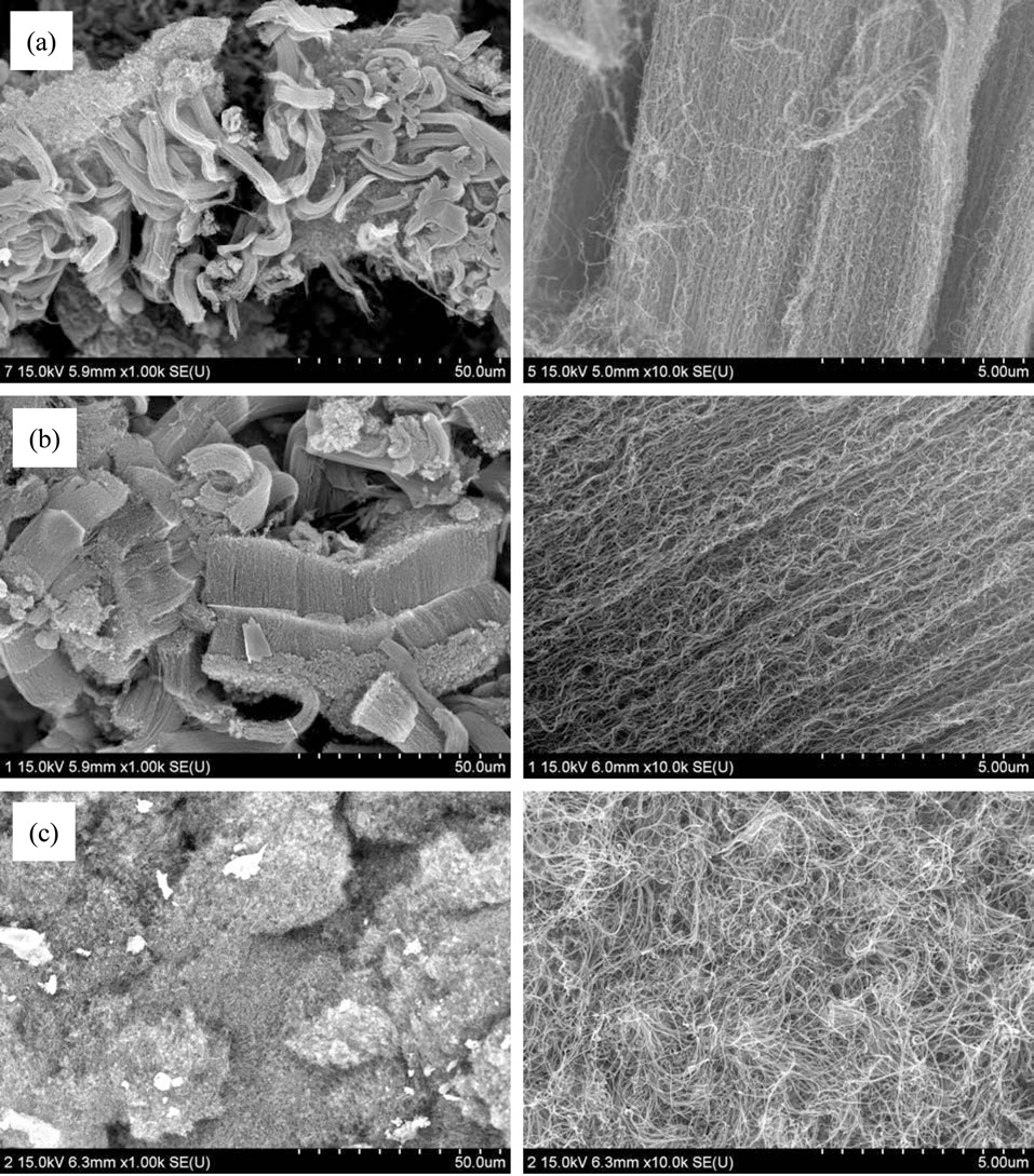
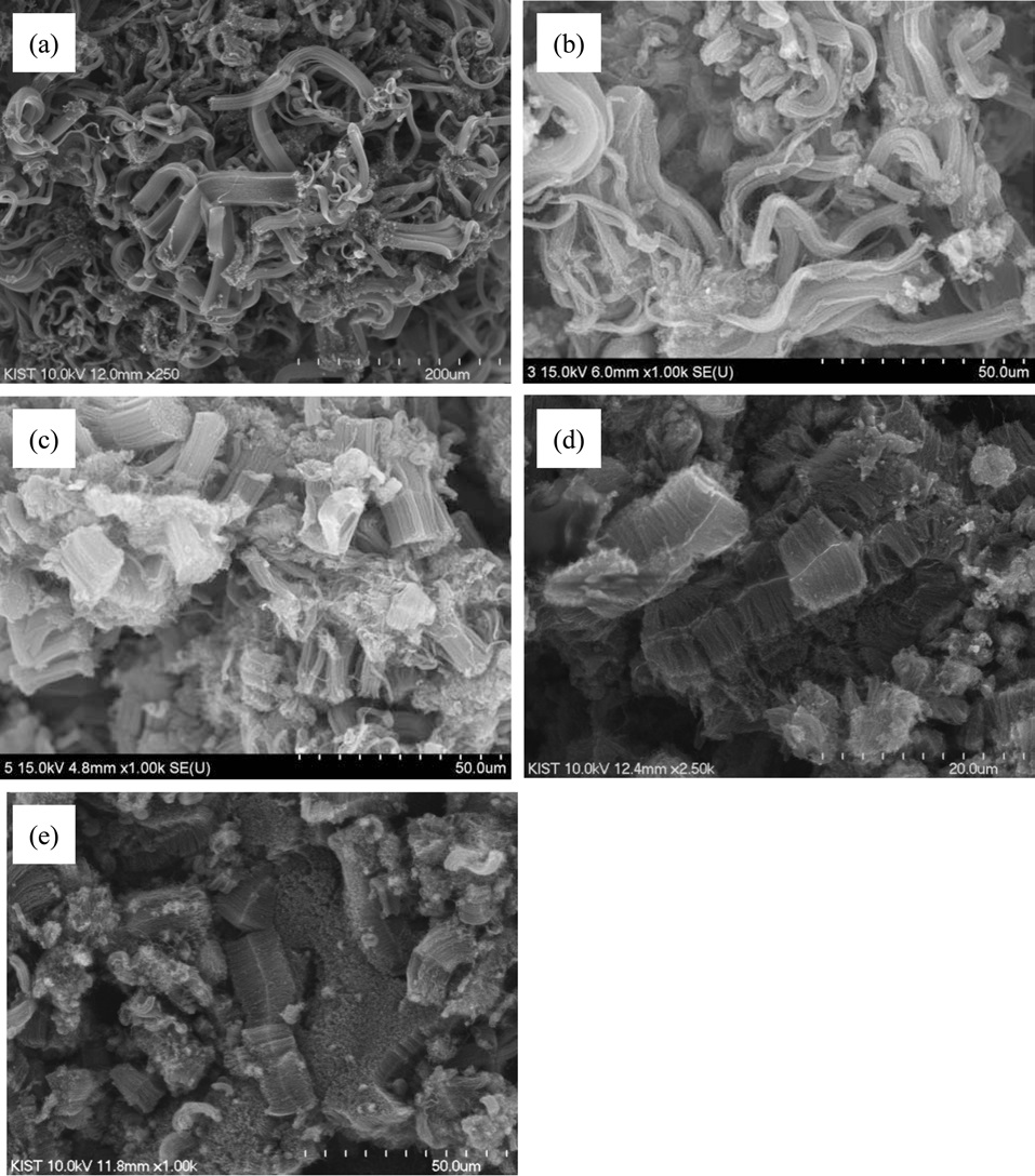
To control the length of the aligned CNTs, we used diverse amounts of Mo-Fe in the MgO supports. When the molar weights of MgO were fixed at 1.000, the molar weights of Mo were in a range from 0.009 to 0.058, and those of Fe were modified from 0.038 to 0.127, as presented in Table 1. Fig. 5 shows the morphologies of the CNTs that were grown on diverse molar portions of catalysts; amounts of Mo-Fe decreased from top to bottom. The yields of CNTs were 5000,
3000, 1000, 500 and 300 wt% in the order shown in Figs. 5a-e. The CNTs in the entire range of molar ratios shown in Fig. 5 seemed to be aligned. Even for low contents of Mo and Fe, such as 0.009 Mol and 0.038 Mol compared to MgO, almost all of the CNTs shown in Fig. 5e seem to be aligned and the MgO supports, which look like white lines, are located in the center of the both-side grown, aligned CNTs. The CNTs may have become well-aligned on MgO supports with sizes larger than 50 μm, as shown in Fig. 5d. The measurement of the length of the aligned CNTs was achieved through analysis of the SEM images; it came out that the lengths of bundled CNTs were 5-10 μm, 10-20 μm, 20-40 μm, 40-60 μm, and more than 100 μm, in order of the increment of the catalyst contents seen in Figs. a-f. The molar ratios of Mo to Mg and Fe to Mg were from 1.0 to 1.2 and from 0.01 to 0.1 in previous works [11-14], whereas those of Mo to Mg and Fe to Mo were from 0.01 to 0.06 and from 0.04 to 0.14 in our work. In
[Table 1.] Molar ratio of catalysts for aligned CNTs

Molar ratio of catalysts for aligned CNTs
short, previous works [11-14] used a catalyst with high Mo content; on the other hand, we used a catalyst with low Mo content. In cases of high content of Mo in the catalyst, high temperature was needed to grow CNTs, because the melting point of Mo is higher than 2000℃. Wang et al. [10] and others [11-14] carried out experiments to obtain aligned CNTs at more than 900℃ with flow of methane gas; however, we could have aligned CNTs at less than 700℃ with a flow of ethylene gas instead of methane gas.
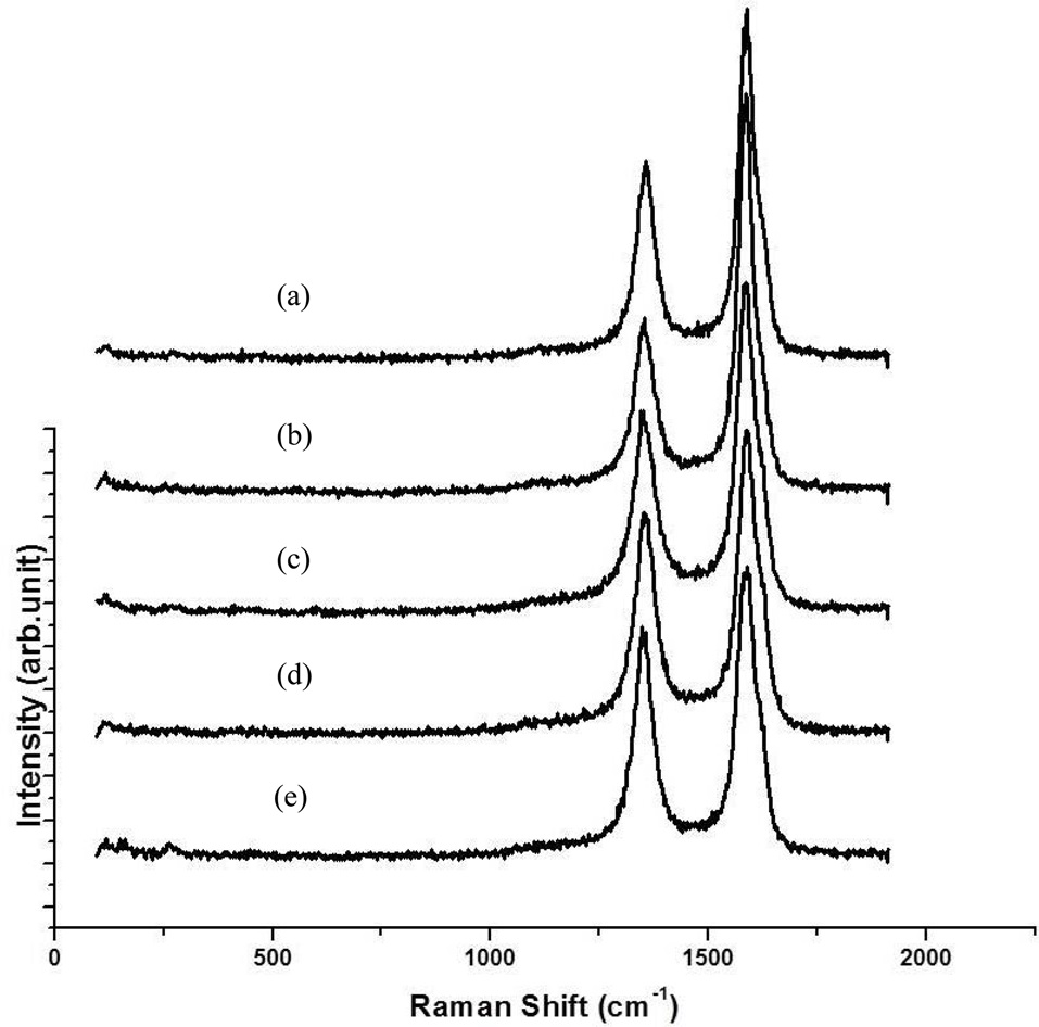
TEM was used to measure the distribution and average diameters of CNTs. The diameter distributions of all CNTs turned out to be around 10-30 nm and the average diameters were from 15-20 nm, as shown in Fig. 6. The diameters of the CNTs shown in Fig. 5f were expected to be smaller than those of other samples (Figs. 5 a-e), but were identical in the range of 10 to 30 nm. These results were similar to our previous results (not published), in which the diameters of the CNTs were around 5-1 nm when they were grown at more than 850℃ with flow of methane; however, with the same catalysts, the diameters of CNTs were about from 10 to 30 nm when they were synthesized at 650℃ with flow of ethylene. Fig. 7 shows Raman spectra of the as-grown CNTs; these results are identical to those shown in Fig. 5. The values of IG/ID were determined to be 1.3, 1.5, 1.4, 1.6 and 1.8 from Figs. 5 a-e, respectively, making them as low as those of commercially produced CNTs.
In this study, we showed the effects of the parameters of the preparing conditions and the compositions of the catalysts on the alignment and length control of CNTs. The key point to make CNTs align was high temperature for the calcination of catalysts, in other words, in our study a temperature of more than 800℃. We controlled the length of the aligned CNTs by controlling the composition of Mo-Fe. When there was high content of Mo and Fe, such as 0.06 and 0.14 mol (molar weight of Mg was fixed at 1), these conditions made the CNTs align, because numerous metal nanoparticles sufficiently existed on the surfaces of the supports. But, even when the portions of Mo and Fe were reduced to as low as 0.010 and 0.040 mol%, short and aligned CNTs were obtained in this study.