The rapid progress in personal and computer communication technologies demands the integration of more than one communication system into a single compact module. This requirement needs compact multi-band planar antennas with good radiation pattern characteristics. The increasing demand for antennas with multi-band capabilities in modern wireless communication systems has attracted public attention. Several systems have been developed and implemented to cope with specific functions and applications, such as Bluetooth, WLAN, Wi- MAX, UWB, etc.
Printed monopole antennas have been used for many kinds of wireless devices because of their low cost, light weight, and ease of fabrication. Various kinds of multi- band antennas have been reported for WLAN, DCS 1,800, and IMT-2000 applications [1]~[11]. In particular, several papers related to the study of rectangular, ring-shaped monopole antennas have proposed these types of devices [12]~[15].
A microstrip line-fed ring antenna with a compact structure [12], however, can only be used for single-band operations. In our previous study [13], we discussed the use of a rectangular ring with an open-ended CPW-fed antenna for 2.4/5.2 GHz operations. A CPW-fed, closed rectangular ring antenna with a vertical strip for WLAN operations was proposed [14] and a CPW-fed, folded monopole antenna with two symmetric strip arms was subsequently proposed for WLAN operations [15].
The present study investigates a novel design for a monopole antenna excited by a microstrip feed line for dual-band operations. The principle of dual-band operations is to introduce a rectangular ring with an openended antenna and a rectangular slit in the ground plane. Experimental results demonstrate that the impedance matching of the proposed antenna depends upon the dimensions of the rectangular slit in the ground plane. The parameters of the antenna are optimized, and the reflection characteristics are presented for a prototype suitable for wireless communication systems, the Digital Cellular System (DSC: 1,710~1,800 MHz) bands, the Personal Communication System (PSC: 1,850~1,990 MHz) bands, the Universal Mobile Telecommunication System (UMTS: 1,920~2,170 MHz) bands, and wireless local area networks (WLAN: 2,400~2,484 MHz and 5,150~5,975 MHz). The detailed design and the results of experiments using the proposed monopole antenna are presented and discussed.
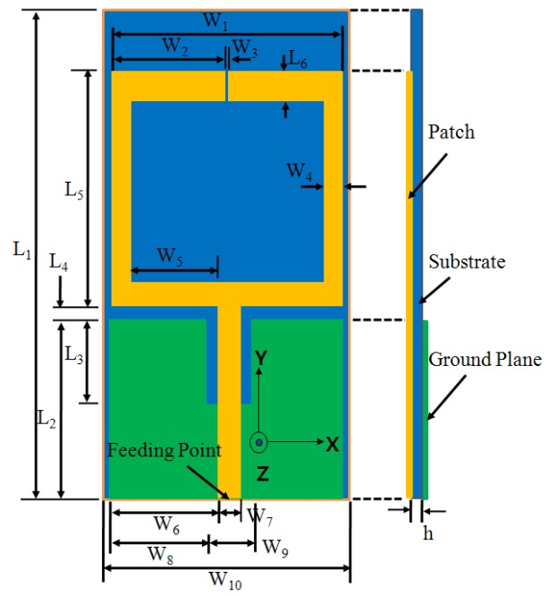
Fig. 1 shows the geometry of the proposed DCS/PCS/UMTS/WLAN monopole antenna designed to facilitate dual-band frequency operations. The design incorporates a total size of the substrate (blue) of 30×50 mm2 (
The rectangular slit is located centrally on top of the ground plane. The antenna was analyzed using Ansoft’s High Frequency Structure Simulator (HFSS) simulation package in order to study the effect of the design parameters on its characteristics [16].
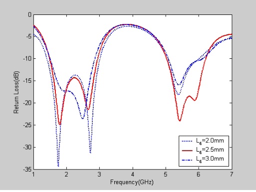
2-1 Effect of the Gap between the Ground Plane and the Rectangular Ring, Open-Ended Antenna, L4
Fig. 2 shows the return loss for the different values of the length of
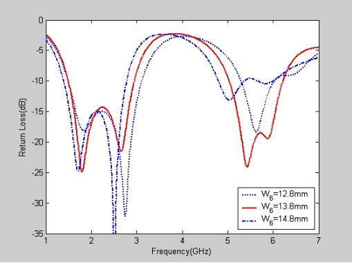
2-2 Effect of the Ground Plane, W6
Fig. 3 shows the return loss for different values of the length of
2-3 Effect of the Ground Plane, W8
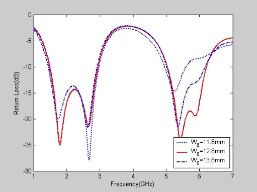
Fig. 4 shows the return loss for different values of the width of
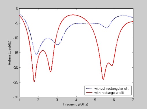
2-4 Effect of the Rectangular Slit in the Ground Plane
Dual-band DCS/PCS/UMTS/WLAN operation was achieved by introducing a rectangular slit in the ground plane, in order to alter the input impedance characteristics.
Fig. 5 shows the return loss with and without a slit in the ground plane. The Fig. shows that the resonant frequency was not generated in the 5,000 MHz bands, and that the impedance bandwidth and return loss characteristics worsened in the absence of a rectangular slit in the ground plane. This indicates that the return loss of the proposed antenna depends on this rectangular slit. In particular, the return loss characteristics of the proposed antenna in 5,000 MHz bands heavily depended on this slit. The optimal values of the rectangular slit width (
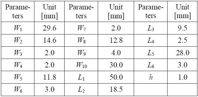
The proposed antenna structure has several design parameters that can handle the resistance and reactance of the antenna input impedance. As such, the dimensions of the proposed antenna were set as shown in Table 1.
[Table 1.] Parameters of the proposed antenna.

Parameters of the proposed antenna.
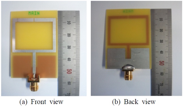
A prototype of the proposed antenna was fabricated with these design parameters, and is shown in Fig. 6(a) and (b).
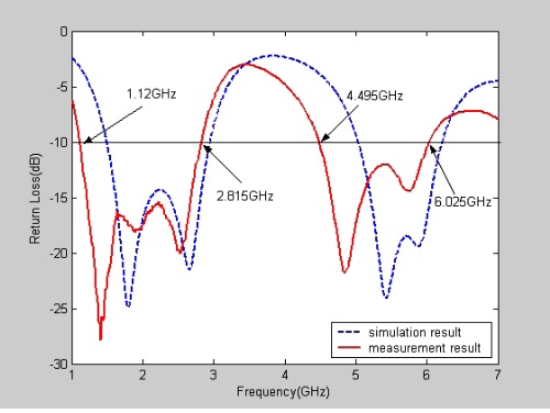
The measured and simulated return losses of the proposed antenna are depicted in figure 7. The frequency response of the return loss of the proposed antenna was measured using an Anritsu MS4644A vector network analyzer at Silla University. The figure shows similar tendencies between both measured and simulated results, but a slight difference in the actual values. This is probably a result of the influence of the coaxial connector that was connected to the patch radiating patch and that was not considered in the simulation. The slight difference is probably due to the influence of the cable that was connected to the proposed antenna during the measurement procedure, which was not considered in the simulation. Differences in relative permittivity may also have been involved.
Two resonant modes are excited at about 1,405 and 4,840 MHz with wide impedance bandwidths. The lowest resonant mode has a 10 dB impedance bandwidth of 1,695 MHz (1,220~2,815 MHz), which covers the DCS/PCS/UMTS/2,400 MHz WLAN bands. The second resonant mode has an impedance bandwidth of 1,530 MHz (4,495~6,025 MHz), which satisfies the required bandwidth of the 5,200/5,800 MHz WLAN bands. Clearly, the design prototype of the proposed antenna has sufficient bandwidth to cover the needs of the DCS/PCS/UMTS/2,400 MHz WLAN bands and 5,000 MHz WLAN bands (1,710~2,484 and 5,150~5,975 MHz, respectively).
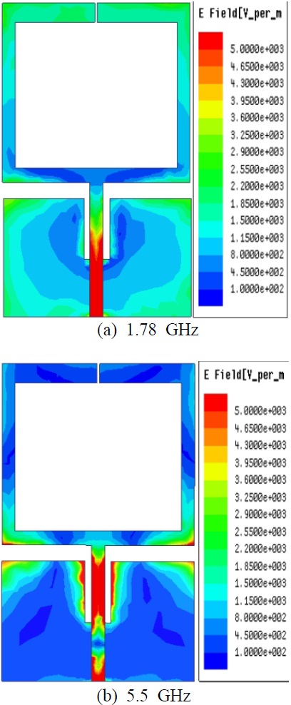
Theoretically, HFSS was used to evaluate and verify the two resonant frequencies, 1,780 and 5,500 MHz, which mainly depended on the lengths of the rectangular ring, open-ended antenna, and the rectangular slit in the ground plane. As expected, the different surface currents were clearly excited by the 1,780 and 5,500 MHz frequencies. Figs. 8(a) and (b) show the surface current density excitations along the rectangular ring, open-ended antenna, and the rectangular slit in the ground plane in the cases of the two resonant frequencies, 1,780 and 5,500 MHz, respectively. As shown in Fig. 8(a), the surface current density excitations of the DCS/PCS/UMTS/2,400 MHz WLAN bands along the rectangular ring, open-ended antenna were observed when the resonant frequency was 1,780 MHz. This implies that the DCS/PCS/UMTS/2,400 MHz WLAN band excitation arises mainly because of the length of the rectangular ring, open-ended antenna. As shown in Fig. 8(b), however, larger surface current densities flowed around the rectangular slit in the ground plane when the resonant frequency was 5,500 MHz. This implies that the 5,000 MHz WLAN band excitation is mainly due to the rectangular slit in the ground plane.
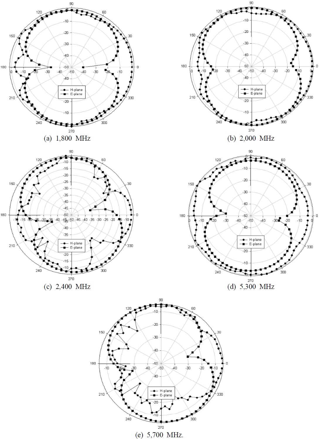
Fig. 9 shows the measured 2D far-field radiation patterns in the E-plane (x-z plane) and H plane (y-z plane). Figs. 9(a)~(d), and (e) show the 2D radiation patterns at 1,800, 2,000, 2,400, 5,300, and 5,700 MHz, respectively. Based on these radiation patterns, the proposed antenna displays omnidirectional radiation characteristics in the H-plane, and monopole-like radiation pattern characteristics in the E-plane at the considered frequencies.
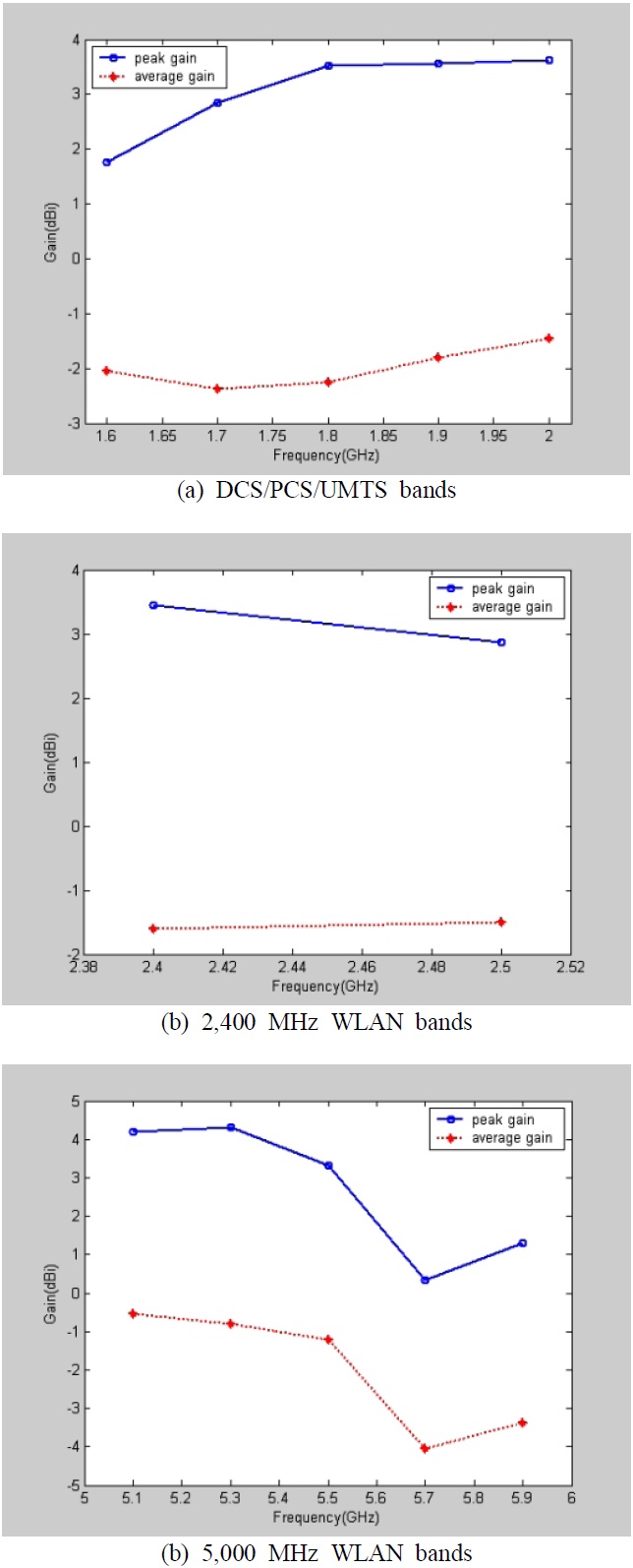
Figs. 10(a), (b), and (c) show the 3D measured antenna peak and average gain for the frequencies across the DCS/PCS/UMTS/WLAN bands. The DCS/PCS/UMTS bands had an antenna peak gain level of about 1.76~3.63 dBi [Fig. 10(a)], the 2,400 MHz WLAN bands, about 2.86~3.45 dBi [Fig. 10(b)], and the 5,000 MHz WLAN bands, about 0.34~4.30 dBi [Fig. 10(c)]. The DCS/PCS/UMTS bands had an antenna average gain level of about ?2.37~?1.46 dBi [Fig. 10(a)], the 2,400 MHz WLAN bands, about ?1.61~?1.50 dBi [Fig. 10(b)], and the 5,000 MHz WLAN bands, about ?4.06 ~?0.53 dBi [Fig. 10(c)]. The 3D maximum peak gain was 2.85 dBi; at 1,700 MHz, 2.884 dBi; and at 1,900 MHz, 3.55 dBi. The 3D maximum peak gain was 3.45 dBi; at 2,400 MHz, 2.884 dBi; and at 2,500 MHz, 2.86 dBi. The 3D maximum peak gain was 3.45 dBi; at 5,300 MHz, 4.30 dBi; and at 5,700 MHz, 0.34 dBi.
A planar, dual-band monopole antenna covering DCS/PCS/UMTS/WLAN bands is presented in this study. The use of a rectangular ring, an open-ended antenna, and a rectangular slit in the ground plane provided the impedance characteristics needed to meet the requirements of DCS/PCS/UMTS/WLAN bands and to facilitate dual-band frequency operations. Various parameters of the proposed antenna were optimized through simulation, and prototyped according to the optimized geometry. A prototype capable of generating two resonant modes to cover DCS/PCS/UMTS/WLAN systems was then tested. The measured ?10 dB impedance bandwidths were 79.06 % (1.22~2.815, 1,695 MHz) and 29.09 % (4.495~6.025 GHz, 1,530 MHz). The proposed antenna, which provides nearly omnidirectional radiation pattern characteristics for frequencies over the DCS/PCS/ UMTS/WLAN bands, showed a measured peak gain varying between 0.34 and 4.30 dBi.