Fourth Generation (4G) mobile communications have received substantial attention, dominating the recent mobile communication market. The Multi-input Multi-output (MIMO) antenna is expected to be a key element in supporting 4G systems [1]~[3]. Because of the limitation of volume in a mobile terminal, MIMO antennas usually have low efficiency and narrow bandwidth. As the biggest piece of conductor around the antenna in a mobile terminal, the ground plane has aroused much interest. It has been widely accepted that the utilization of a ground plane could substantially improve the performance of small antennas [4]. In the MIMO system, the value of Envelope Correlation Coefficient (ECC) is a key parameter in evaluating the performance of an antenna. In general, a small ECC value guarantees a good isolation performance in a MIMO system. However, isolation is not directly related to the ECC in a MIMO system with small antenna elements because of the low efficiency. So some popular approaches to enhancing isolation performance do not effectively improve ECC simultaneously [5]. The only valid method for improving ECC in a small MIMO system is to increase the pattern diversity of different antenna elements. In a MIMO system with small antenna elements and quasi-omnidirectional radiation patterns, the most effective way to lower the ECC is to increase the separation angle between the different patterns.
In this paper, a MIMO antenna designed for 4G mobile application is proposed. By utilizing the resonance of ground planes and an inductive coil, the proposed antenna improves both bandwidth and efficiency properties. By modifying the radiation patterns orthogonally, the MIMO antenna obtains a low ECC of below 0.1. Moreover, an additional radiator is designed to cover WiMAX, WLAN, and Bluetooth bands with frequencies ranging from 2 GHz to 2.7 GHz.
Ⅱ. Antenna Design and Performance
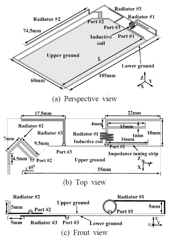
The geometry of the proposed MIMO antenna is shown in Fig. 1.
The proposed MIMO antenna consists of three radiating elements: upper ground, lower ground, and FR4-substrate (
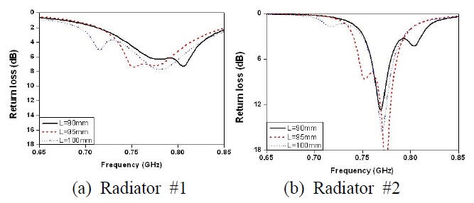
The return losses of Radiators #1 and #2 with respect to variations in the length of the ground plane (L) are shown in Fig. 2(a) and (b). The resonance frequency of the mode induced by the ground planes is determined by the length (L) of the ground planes, which is approximately 0.5
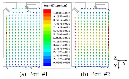
The corresponding current distributions on the ground planes at the resonance frequency of the ground planes (0.752 GHz) are shown in Fig. 3. The currents on the ground planes excited by both Ports #1 and #2 flow mainly in the direction of the x-axis. The maximal strengths of both currents occur at the center of the ground planes. As the observation point moves from the center toward the edge of the ground planes, the strengths of the currents decrease. The quasi-TMz100 modes are generated within the dielectric substrate between the grounds.
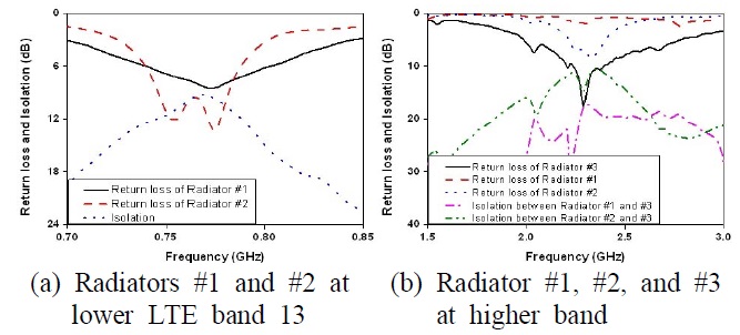
The measured return loss and isolation characteristics of the designed antenna are shown in Fig. 4 (a) and (b). The chart shown in Fig. 4 (a) confirms that Radiators #1 and #2 achieve sufficient 6 dB bandwidths to cover the LTE band 13 (0.745~0.787 GHz). The proposed two radiators have isolation above 9 dB over the LTE band 13. Fig. 4 (b) confirms that Radiator #3 achieves a 6 dB bandwidth from 2.0 GHz to 2.7 GHz, covering WiMAX, WLAN, and Bluetooth bands, simultaneously. Radiator #1 does not operate at a higher band. The 6 dB return loss bandwidth of Radiator #2 is narrower than that of Radiator #3 and would not be used at a higher band. Fig. 3 shows that the isolation between Radiator #2 and #3 is above 10 dB.
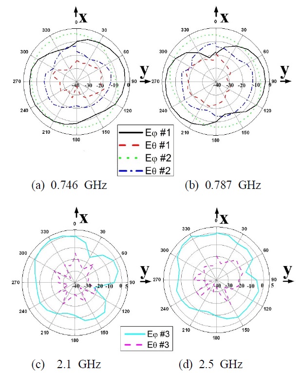
The measured radiation patterns are shown in Fig. 5. According to the measured results, the peak gain of Radiator #1 is above ?1.22 dBi, and the peak gain of Radiator #2 is above ?2.89 dBi. The peak gain of Radiator #3 is above 1.68 dBi. As expected, the total radiation patterns of Radiators #1 and #2 have separation angles of around 90°, which lowers the ECC value.
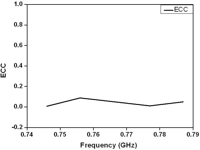
The ECC is calculated using the measured radiation patterns, as shown in Fig. 6 [7]. The proposed MIMO antenna has an excellent ECC of below 0.1 over the LTE band 13 because of the nearly orthogonal separation angles.
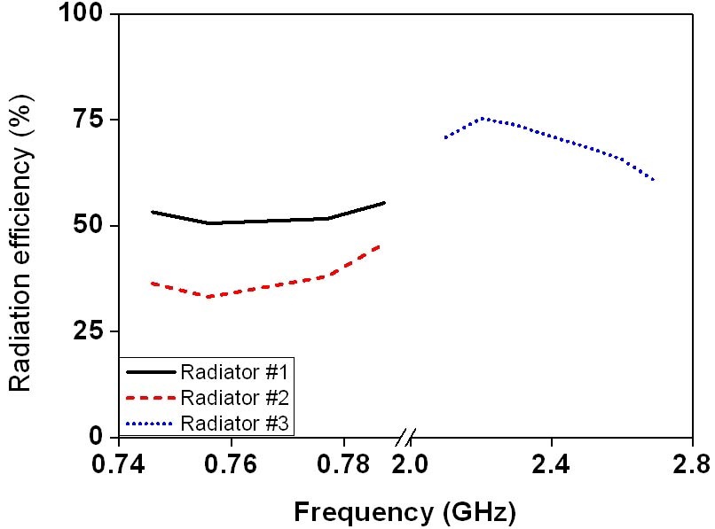
The radiation efficiencies of the proposed MIMO antenna are shown in Fig. 7. As this figure shows, the radiation efficiency of Radiator #1 is above 50 %, and the radiation efficiency of Radiator #2 is above 33 %. The results confirm that the inductive coil in Radiator #1 effectively improved the radiation efficiency. The radiation efficiency of Radiator #2 is lower than that of Radiator #1 because of the stronger opposite-directional image current on the ground planes. Moreover, the radiation efficiency of Radiator #3 is above 60 %.
This paper proposed a MIMO antenna for 4G mobile applications. By utilizing the resonance of ground planes and an inductive coil, the proposed antenna achieves a simplified design in addition to improved bandwidth and efficiency. Moreover, the proposed MIMO antenna has an excellent ECC value of below 0.1 because of the nearly orthogonal radiation patterns of the two radiating elements. These properties make the proposed MIMO antenna a promising choice for 4G mobile applications.