Near-field wireless power transfer has been receiving extensive interest recently, and it is now being widely studied. A near-field wireless power transfer system can be viewed as a coupled antenna system in a near-field region. Hence, the field pattern that an antenna generates has a significant effect on the behavior of the wireless power transfer system. Many researchers, however, have tried to transmit power wirelessly in a near-field region using antennas that generate a mostly fundamental spherical mode [1]~[5]. In this paper, we attempt to determine a field pattern that is more efficient for wireless power transfer than that of the fundamental mode. The results of our theoretical investigation showed that antennas generating higher-order spherical modes are more efficient for transferring power wirelessly unless the radiation efficiency is too low. These results were verified by an experiment.
Ⅱ. Mutual Coupling between Two Antennas
We determine the mutual coupling between two antennas under the assumption that the antennas are canonical minimum scattering antennas. The canonical minimum scattering (CMS) antenna does not scatter electromagnetic fields when its local port is open-circuited [6]. Many antennas that are small, relative to wavelength, can be modeled as minimum scattering antennas [7].
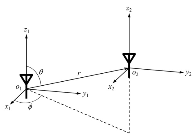
The Z-parameter of two coupled CMS antennas can be derived using the method described in [8]. To determine the Z-parameter, we first represent the fields that antennas generate as a superposition of spherical modes. The spherical mode functions and ordering of modes adopted in this paper are the same as those used in the EM simulator FEKO [9]. Let a reciprocal and matched CMS antenna be located on the origin of coordinate system 1 and an identical antenna be located on the origin of coordinate system 2, as shown in Fig. 1. Let the modal transmitting pattern [8] of the antennas be T, the modal receiving pattern [8] of the antennas be R, and the input impedance of the antennas be Zin. The Z-parameter between the two identical matched and reciprocal CMS antennas is then as follows:


where the element in the
where
is followed by
The power transfer efficiency is defined as the power dissipated at the load in the receiving antenna divided by the power accepted by the transmitting antenna. If the Z-parameter of two coupled antennas is given, then the maximum power transfer efficiency can be calculated by the following equation [11]:
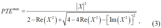
where
Ⅲ. Enhancement of Maximum Power Transfer Efficiency Using Higher Order Spherical Modes
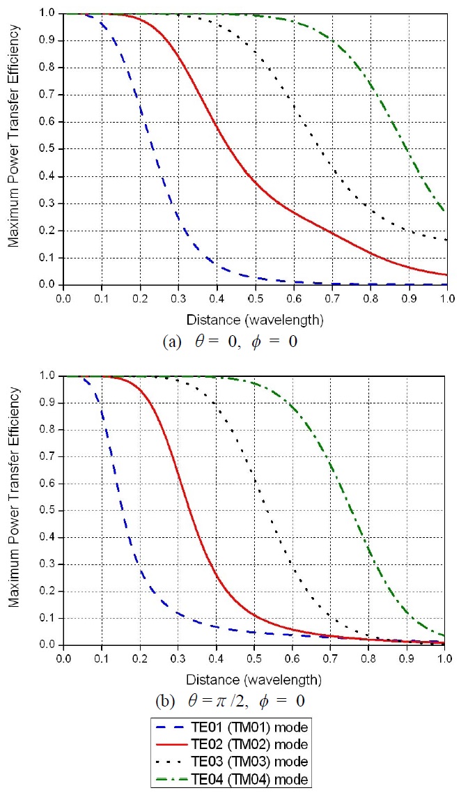
It might be worth investigating the effect of higherorder modes on wireless power transfer. Intuitively, one would expect that the higher-order mode would be efficient for wireless power transfer. Electric and magnetic energy stored outside a sphere surrounding an antenna and the quality factor (Q) increase as the mode number increases [12]. Therefore, the higher-order mode may be able to increase the coupling coefficient. According to [13], a wireless power transfer system with a large coupling coefficient and large Q is efficient for wireless power transfer.
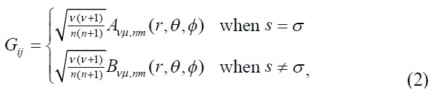
We examine whether the higher-order mode is indeed efficient for wireless power transfer. We assume that the antennas are CMS antennas and generate only one TE0n (TM0n) mode for simplicity. Using (1), (2), and (2.107) in [14],

where
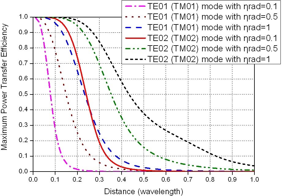
The maximum power transfer efficiency increases with the radiation efficiency since the greater the radiation efficiency, the larger the magnitude of
When antennas generate multiple spherical modes, antennas generating higher-order spherical modes may be efficient for wireless power transfer. Because the magnitude of the imaginary part of
When antennas are not CMS antennas, a value is added to the Z-parameter calculated by (1) because of multiple reflections [15]. If the added value is not large, we can guess that the higher-order mode is also efficient when the antennas are not CMS antennas.
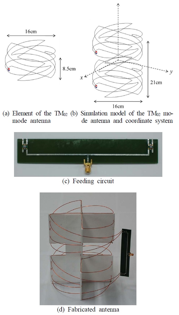
To verify the theory, we designed an antenna generating the TM01 mode and an antenna generating the TM02 mode. We then conducted a wireless power transfer experiment.
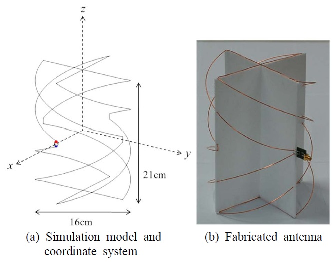
To increase the radiation efficiency of the antennas, we chose a folded cylindrical helix (FCH) [16], [17]. A four-arm 1/2 turn FCH antenna with a radius of 8 cm and a height of 21 cm was used as the TM01 mode antenna (Fig. 4). A balun was connected to the feeding port of the antenna. The TM02 mode antenna was composed of two four-arm 1/2 turn FCH antennas with a radius of 8 cm and a height of 8.5 cm. The axes of the two FCH antennas coincided, and the distance between the centers of the two antennas was 12.5 cm (Fig. 5). We excited each feeding port of the two element antennas so that the phase difference between the currents on the two antennas was 180°. To excite out of phase, the baluns connected to the feeding port were placed in opposite directions. The size of the TM02 mode antenna was the same as that of the TM01 mode antenna. All antennas were made of copper wire with a diameter of 1 mm.
We simulated the antennas with FEKO, which is based on the method of moments. The S-parameter of the feeding circuits were measured and used in the simulation. Table 1 shows the spherical mode coefficients generated by each of the antennas. When the spherical mode coefficients were computed, a reactance that matched the antenna was connected to it. In Table 1, the TM01 mode antenna generated mostly TM01 mode, and the TM02 mode antenna generated mostly TM02 mode. The radiation efficiency of the TM01 mode antenna was 81 % at 260 MHz, and the radiation efficiency of the TM02 mode antenna was 20 % at 274 MHz.
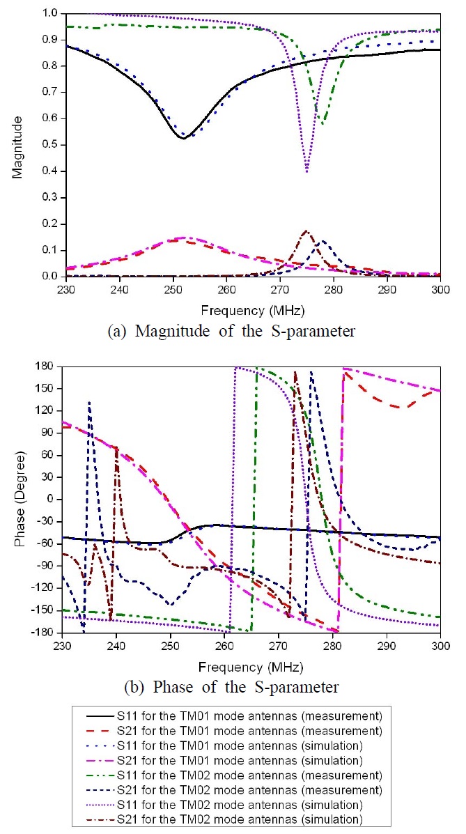
We simulated and measured the S-parameter of two coupled TM01 mode antennas and the S-parameter of two coupled TM02 mode antennas. Here,
The maximum power transfer efficiency was calculated from the S-parameter using the simultaneous matching formula [18]. In the case of TM01 mode antenna, the maximum power transfer efficiency was the largest at 260 MHz. In the case of TM02 mode antenna, the maximum power transfer efficiency was the largest at 274 MHz in the simulation, while the maximum power transfer efficiency was the largest at 277 MHz in the measurement. Fig. 7 shows the maximum power transfer efficiencies obtained from the CMS theory, simulation, and measurement. The curve for CMS was obtained using (3), (4), and the radiation efficiencies obtained with the simulation. The measured maximum power transfer efficiency was 0.26 at 260 MHz for the TM01 mode antennas and 0.42 at 277 MHz for the TM02 mode antennas when the center-to-center distance between the antennas was 30cm. The maximum power transfer efficiency for the TM02 antenna increased by 62 % compared to the TM01 mode antenna. Notice that the maximum power transfer efficiency for the TM02 mode antenna is higher than that for the TM01 mode antenna with a radiation efficiency of 1. The measurement agrees with the curve for CMS in the case of the TM01 mode power transfer system, whereas there is an error between the measurement and the curve for CMS in the case of the TM02 mode power transfer system, which was because the antennas are not CMS antennas.
[Table 1.] Spherical mode coefficients of the matched antennas.
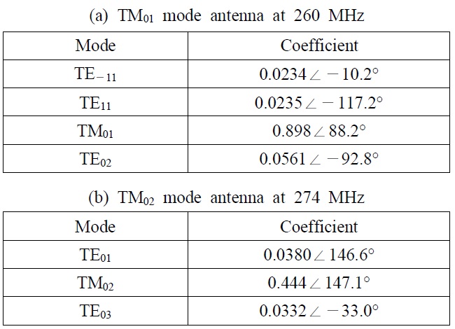
Spherical mode coefficients of the matched antennas.
Although the antennas used for the experiment were not CMS antennas, this experiment showed that the higher- order mode is more efficient than the fundamental mode.
To investigate the characteristics of wireless power transfer, we determined the Z-parameter between two CMS antennas. Using the formulas for the Z-parameter and the maximum power transfer efficiency, we showed that the power transfer efficiency increases as the mode number or radiation efficiency increases.
We experimented with the wireless power transfer using antennas generating TM01 mode and antennas generating TM02 mode. The maximum power transfer efficiency for two TM02 mode antennas was 62 % higher than that for two TM01 mode antennas when the center- to-center distance was 30 cm.
Although the theory was developed under the assumption that the antennas are CMS antennas, we demonstrated through the experiment that the higher-order mode antenna can be more efficient than the fundamental mode antenna even when the antennas are not CMS antennas.
It is important to note that the higher-order mode is not always efficient for wireless power transfer because the latter is influenced not only by the spherical modes, but also by the radiation efficiency. Therefore, in practice, the radiation efficiency of antennas should be considered when determining the best spherical mode to use.