Various consumer electronic applications require 3- dimensional (3D) models of street scenes, for example for virtually flying or driving through a city, augmented reality, urban planning, or for documentation purposes (of city scenes at a particular point in time). The design of fully or semiautomatic methods for time-efficient modeling of city scenes has become has become an active research area, with manifold interesting contributions already in computer graphics and computer vision.
Due to the rapid increase of digital photography, imagebased modeling approaches are today a cost-efficient and feasible way for doing large-scale city modeling. Often it is actually not required to provide very detailed reconstructions of buildings; for applications such as virtual tours or path planning, it is sufficient to provide some kind of 3D sketches. Even only ‘rough’ 3D textured street views will define progress compared to common GPS-based 2D maps or textureless road models, as typically used today in cars as a navigation tool. A visual impression of the 3D environment helps to navigate in unknown areas. This can be achieved by supplying realistic 3D street views of a route, for example, by simplified but realistic looking, texturemapped 3D building models.
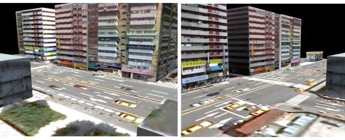
The aim of this paper is to develop a framework that takes a set of dense spherical panoramic images and an orthogonal aerial image of that area as input image data, and outputs texture maps and height information of the buildings through a semi-automatic process. The reconstructed 3D building models are textured with building elevation images, automatically extracted from the panoramic images, for providing a realistic impression of the street view, as illustrated in Fig. 1.
Progress in sensor technology (e.g., laser scanners or panoramic cameras) has contributed in recent years to the success of 3D modeling techniques by providing various options for input data [1]. Aerial photogrammetry provides height maps (in particular the height of buildings) using stereo images or laser scanners [2-5]. Those height maps support the construction of 3D city models. However, models derived from aerial scans typically lack realism at ground level because aerial image data carry only limited information about textured side views (i.e., the facades) of buildings.
Automated texture mapping for 3D city models has been studied in [6-11] using ground-level image data. There are two major issues, namely visible seams in calculated textures due to variations in lighting or image resolution, and excessive time requirements due to the need for automated pose recovery for the applied multi-view approach (using planar ground-level images).
Some authors have suggested using recorded images only for reconstructing 3D street models [12-14], without including any depth information recorded by a laser scanner. For example, [13] discusses a plane-sweep algorithm where depth is estimated from multiple images. This ground-level image-based approach generates 2.5D models only rather than 3D models.
The authors of [15] propose the use of cylindrical panoramic images (for texture mapping based on groundlevel data). They assume an approximate localization of recorded panoramas, and apply a voting process for the process of registration of aerial and panoramic images. They use sparsely recorded panoramic images, resulting in a lack of texture, and also a continuation of the problem of visible seams between overlapping textures.
This paper proposes an image-based approach. We derive 3D building models from aerial images as publically available on Google Maps, and from recorded spherical panoramas. The generated models are approximate, represented by textured planar faces. Textures are extracted from spherical panoramas. The recovered camera trajectory defines essential information, and we describe how to achieve that by using global positioning system (GPS) data and selected key frames of spherical panoramas.
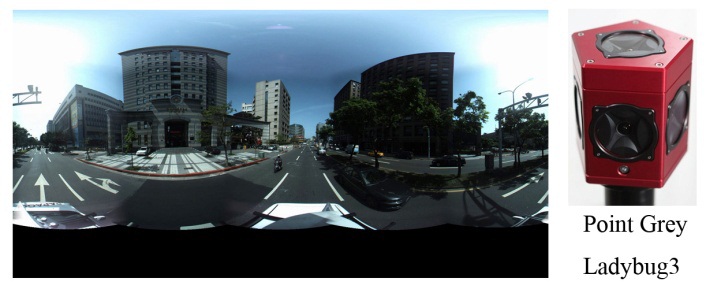
The input data of the developed system are from two types of image sources. They provide a dense set of ground-level spherical panoramic images and a nearlyorthogonal aerial view. We also applied the GPS information associated with the recorded panoramic images. For panoramic image acquisition we used a Ladybug 3 camera (Point Grey Research, Richmond, Canada), mounted on the top of a car. This panoramic video camera consists of six high quality Sony charge-coupled device (CCD) sensors, which capture six planar images, five looking horizontally outwards and one looking upward, with a frame rate of 15 images per second. Six images were then stitched together using the multiperspective plane sweep approach of [16] to generate a 720-degree spherical panoramic image with image resolution 2,048 (width) × 1,024 (height) pixels.
An example of a captured panoramic image, which has been transformed into a rectangular representation, and the Ladybug 3 camera, are shown in Fig. 2. The car was also equipped with a GPS device. This location information is used for initialization and bundle adjustment in the camera path recovery process. The other input image is a nearlyorthogonal aerial image of the area to be reconstructed. The image is generated by stitching together different sections of local aerial image blocks, as available in Google Maps.
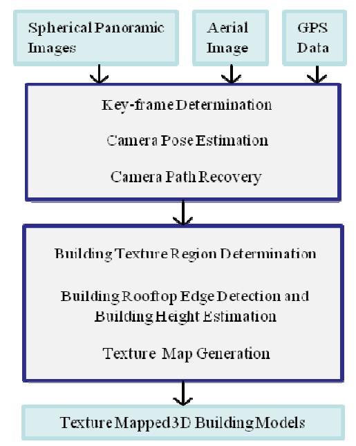
For a sketch of the proposed system pipeline, see Fig. 3. The entire modeling process is grouped into two stages. The main task in the first stage is to recover the camera path based on video and GPS data.
The goal of the second stage is to generate building texture maps from available panoramic images with the help of specified clues (i.e., buildings' footprints) on the aerial image. Some reasonable assumptions about the input data of the proposed approach are described as follows:
The iamge projection model of each recorded panoramic image is defined by spherical projection with respect to a single projection center (i.e., we use a single-center projection model). A 3D Cartesian coordinate system is defined for each panoramic image, having its origin at its corresponding projection center. Each individual coordinate system is used for representing the location and orientation of the camera in the 3D space where a particular panoramic iamge is captured with respect to the world coordinate system. Moreover, the panoramic images are assumed to be recorded along a smoth and contimuous path. GPS information is given defining some of the panoramic iamge acquisition locations. Furthermore, the aerial image as obtained from Google Maps is assumed to be an orthogonal aerial image, and building footprints on such an iamge are assumed to be given, using the same mathod as proposed in [15]. Building footprints ar represented by a set of polygons, which can be calculated by preprocessing and segmentation of the aerial map, or simply by manual specification. The output of the system is a set of 3D polygonal building models, texture mapped by building textures extracted from the panormic iamges. Fig 1 illustrates a street-view of resulting 3D building models produced by the proposed approach.
IV. CAMERA TRAJECTORY ESTIMATION
The first in the system pipeline deals with the camera trajectory estimation task, which is an essential step towards accurate registration of two types of input images. Currently, registering the recovered camera trajectory to the aeral image is done manually by region-wise assignments of the camera path to the aerial map. Consequently, we derive the coordinates of images representing the locations in the aerial image associated with the recorded panoramic images.
Only selected key frames among a huge set of input video data (i.e., spherical panoramic images) are used th estimate the movement of the camera along the streets. A feature detection algorithm is applied to each ot these selected panoramic images, and feature point matching is performed between successive selected images. Matching results enable us to recover the essential matrix. describing the spatial relationship between both imaging coordinate systems. Relative orientation, represented by a rotation matrix, and prosition, represented by a unit vector, of both seccessive panoramic iamges are derive (as common in computer vision) from the essential matrix.
The camera trajectory is recovered based on a point cloud reconstruction of the scene and bundle adjustment based on available GPS information. The camera path is refined by registering it to the aerial image. The following subsections describe the methods used in each step.
The image acquisition rate of the Ladybug 3 panoramic video camera is 15 frames per second (fps). The average speed of the image adquisition vehicle is about 35 km/hr (of course nto constant due to traffic-related events). Therefore, a large set of panoramic images is captured within a very short period of driving. Normally, one recording session is about 10 to 20 minutes. For the goal of recovering the camera’s trajectory, a large fraction ot the input image data may be considered to be redundant, because it is not only unnecessary for improving the accuracy of the estimated trajectory for improving the accuracy of the estimated trajectory, but may even add more noise to the trajectory calculation process. Therfore, only a selected set of key frames is used for the camera trajectory recovery process. In other words, the task for the first step is to eliminate redundant images.
[Algorithm 1] Eliminating the Redundant Images
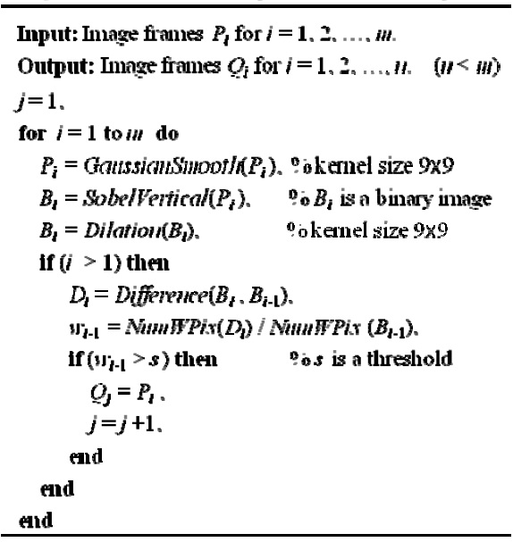
Eliminating the Redundant Images
The first filter applied to the input sequence is to select only every
For solving this task, we prefer the spherical represen-tation of panoramic images rather than cylindrical images. This is because pairwise relative camera poses can be recovered by directly adopting well-known camera self-calibration methods (such as the 8-point algorithm) originally developed for planar images. This, in turn, is because a single projection centre has been assumed in the spherical image representation. Those algorithms have shown to be robust to error, and it is possible to achieve real-time performance. Note that, in order to adopt those camera self-calibration algroithms to the panoramic image situation, a single-centre projection constraint must be
ensured.
The camera pose estimation approach is as follows: First, a feature detection algorithm is applied to each of the selected panoramic images, and then a feature point matching search is performed between each pair of successive images. The matching results enable us to recover the essential martix that describes the spatial relationship (i.e., camera pose) between two imaging coordinate systems. The spatial relationship between two successive panoramic images can be characterized by a rotation matrix, describing the relative orientation, and a unit vector, descriing the relative location.
Correspondences between image points are established by acale-invariant feature transform (SIFT) feature detection plus SIFT-base matching [17]. In the algorithm, a single threshold, denoted as
The 8-point algorithm is employed to estimate the essential martrix. The algorithm utilizes the epipolar constraint, more specifically the coplanarity constraint, for calculating the essential matrix. The coplanarity constraint can be assured by vector arithmetic; thus, the implementation of the 8-point algorithm is independent of the geometrical form of the image manifold (i.e., planar, spherical, or cylindrical). A 2-pass approach is proposed to obtain the derived according to a smaller set of corresponding image points, which is the matching result associated with a relatively large threshold value t. Those sparse corresponding points are believed to be more accurate but less desriptive. Next, a smaller threshold value
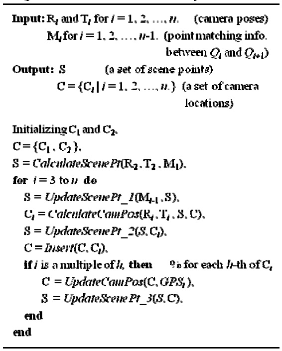
[Algorithm 2.] Camera Path Recovery

Camera Path Recovery
The derived essential matrix is used to solve for the external camera parameters R and T, which stand for the rotaion matrix and the translation vector, respectively. The algorithm leads to two valid solutions for R and two solutions for T pointing in opposite directions. The correct solution translation T can be obtained by assuming forward motion of the camera. To identify the correct solution for R, scene points based on already processed panoramic images are reconstructed with repect to the 3D world coordinate system. Each valid solution of R is used to calculate new scene points. Ideally, the majority of those new scene points should coincide with previously reconstructed scene points. The correct solution of R is then determined by evaluatint these 3D reconstruction results.
Pairwise external camera parameters are integrated, one by one, to obtain global camera motion, and thus the camer’ trajectory. The major drawback of such a method is that the camera parameter estimation error would propagate through the integration process. In order to deliver a more accurate and more efficient solution to this problem, the GPS information was incorporated into the path recovery algorithm, as summarized below in Algorithm 2. Since the accuracy of GPS varies from 1 to 5 m, it is sensible to correct the path drift every 50 m based on the GPS reading. The value of
There are three different functions for updating the reconstructed 3D scene points in the algorithm. All of the scene points are stored in a database S, in which the visibility of each scene point with respect to each camera location is also available and is continously updated by function
The second stage in the system pipeline deals with the generation of texture maps for buildings based on the recorded panoramic images. At this stage, it is assumed that the camera path, which specifies the locations of key panoramic image frames, has been registered th the aerial image.
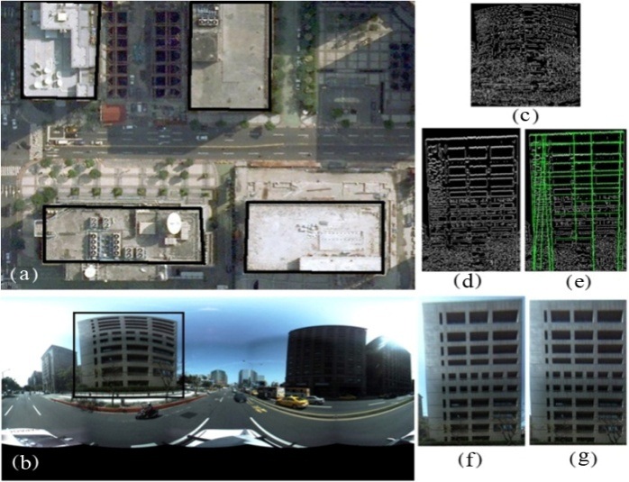
In order to extract building textures from the panoramic images, first, the image region containing the selected building is determined using the provided footprint boundaries of this building in the aerial image. Next, the system looks for the building’s rooftop edge in the panoramic image within the estimated region. Once the building’s rooftop edge is identified, it is able to extract more precisely a building texture map from this image region. Finally, the building texture must undergo a warping and rectification process before it cal be used for texture mapping. The height of the building can also be estimated based on the image registration result and the location of the identified building’s rooftop edge.
The usage of texture maps not only enhances the visualization of the 3D models but also verifies height information about the buildings. The following subsections report about techniques involved in the second stage of the system pipeline.
>
A. Determination of a Texture Region of a Building
For each building footprint, shown in the aerial image, our main interest is to extract the front facade viex of the building from the panormaic image.
An example of an extracted building texture and intermediate procedures are illustrated in Fig. 5. The first step is to determine a building’s textured region, denoted by
The system selects a panoramic image
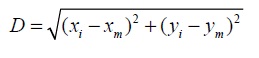
where (
Then, in the selected panoramic image
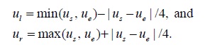
The vertical range of region
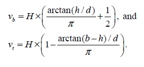
>
B. Rooftop Edge Detection and Height Estimation
Canny edge detection is now applied to region
Let
The determined rooftop edge of the building, denoted as
The building’s facade image is generated by first backprojecting the color panoramic image region
The program was mainly written in MATLAB (Math Works, Natick, MA, USA) and partially in C++. The experiments were performed on a Windows XP (Service Pack 3) operating system running on an Intel(R) Core(TM) i7 CPU 920 2.67 GHz with 3 G of RAM. A Point Grey Ladybug 3 digital video camera was mounted on top of a car and used to capture the spherical panoramic images. The car was moving at an average speed of 35 km/hr, and the camera captured 15 panoramic images per second. In this way, adjacent panoramic images were captured at locations approximately one meter apart. The car was also equipped with a GPS system. The resolution of the recorded panoramic images was 2,048 (width) × 1,024 (height).
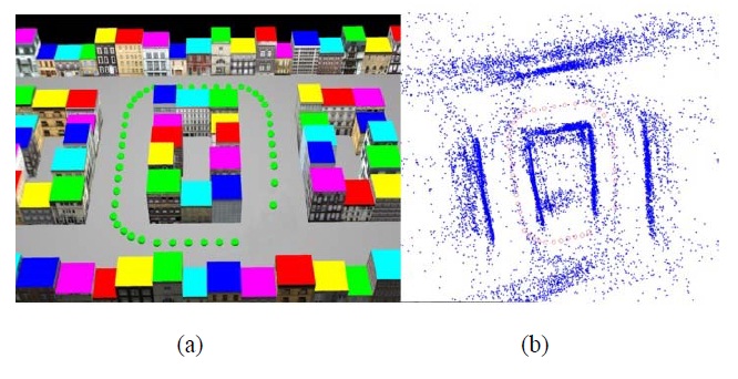
The proposed approach was also tested on synthetic image sequences. One reason for this was that there was no sufficiently accurate ground truth available for testing the path recovery approach in the real world. Therefore, we constructed a 12 × 20 unit (a “unit” as used in the program) synthetic city and street environment using commercially available 3D modeling software (Fig. 4a). The buildings were texture-mapped using textures of real buildings. Fig. 4 illustrates a synthetic world experiment on path recovery. In this experiment, 50 panoramic images were generated at locations indicated by the shown dots. The estimated camera path is represented by a set of circles. The average drift of the resulting camera path from the actual path is equal to 0.324 units. This result was not yet based on any bundle adjustment strategy.
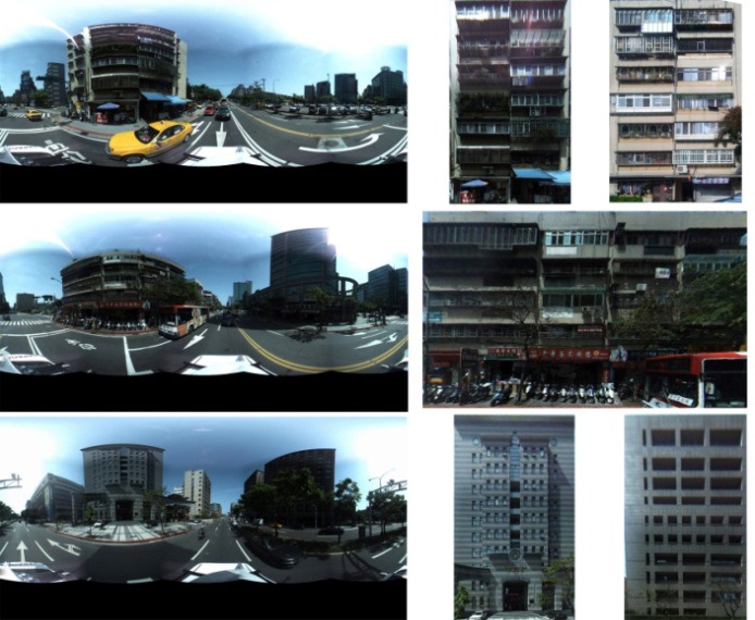
Fig. 6 shows two close-up views. A virtual camera was implemented for recording panoramic images in the virtual world. A few examples of captured spherical images are shown in Fig. 7a, which have been transformed into planar rectangular images.
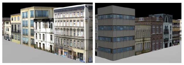
The aerial image of that area was obtained from Google Maps. Examples of building texture maps, generated from the panoramic images, are shown in Fig. 7b. Fig. 8 illustrates 3D models of buildings obtained semiautomatically by following the discussed approach.
This paper presented an approach for deriving a realistic looking 3D polyhedral city model. Two types of input images have been used, namely a sequence of spherical panoramic images and a nearly orthogonal aerial image of that area, generated from available aerial image data. Both kinds of images are used cooperatively to recover the camera path and for a subsequent automated extraction of building texture maps from available input sequences. Relative directions and positions of all the panoramic images used were estimated within a fully automatic process with reasonable accuracy, and the camera path was recovered with the help of sparse GPS data.
Moreover, the developed algorithm is able to automatically search (within a recorded panoramic image sequence) for an appropriate initial texture window, and to generate from this a rectangular front-view texture for each building to be reconstructed. At the same time, we can also estimate the height of the building. These capabilities are useful for performing large-scale 3D city modeling.