The development of antenna technology in wireless local area network (WLAN) applications requires high-speed data connectivity, which demands good performance with dual operating frequencies. WLANs and connecting portable terminals have been governed through standardization of frequency bands defined by various standard protocols, namely, IEEE 802.11a (5.15?5.35 GHz and 5.725?5.85 GHz) and 802.11a/g (2.4?2.484 GHz). At present, WLAN technology has been one of the most successful and fastest growing wireless communications technologies in the world. Among portable devices, antennas play an important role among the key components in determining radio-frequency (RF) performance of the end product.
As WLAN communication becomes more and more popular, the need for a printed monopole antenna designed with a low profile, light weight, flush mount, and simple structure increases. Recently, multiband antennas for WLAN applications have been reported [1-13]. In particular, a few papers have proposed rectangular ring shaped monopole antennas [14-18]. A microstrip line fed ring antenna with compact structure [14] allows for single band operation only. In our previous study [15], we discussed a rectangular ring with open-ended coplanar waveguide (CPW)-fed antenna for 2.4/5.2 GHz operation. A CPW-fed closed rectangular ring antenna with a vertical strip for WLAN operation was proposed [16]. Also, a CPW-fed folded loop antenna for satellite DMB operation was proposed [17], and a CPW-fed folded monopole antenna with two symmetry strip arms for WLAN operation was also proposed [18].
In this study, a novel rectangular ring with an open-ended monopole antenna with an inverted L-strip suited for dualband WLAN applications was designed. The proposed antenna comprises a rectangular ring with an open-ended, inverted L-strip, and a rectangular slit in the ground plane. By properly selecting the dimensions of the proposed antenna, good dual broadband bandwidth and radiation characteristics suitable for WLAN 2.4/5.2/5.8 GHz operations can be achieved. The detailed design considerations and experimental results of the proposed monopole antenna for WLAN operation are presented and discussed below.
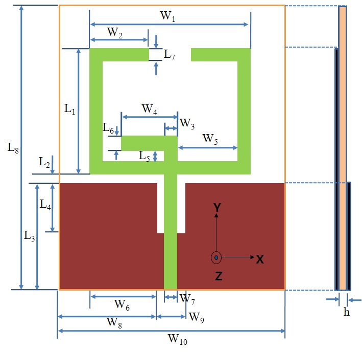
Fig. 1 shows the geometry of the proposed WLAN monopole antenna for achieving dual band frequency operation. In this design, the total size of the substrate was 46.4 × 50 mm (W10 × L8). The proposed antenna was fabricated on one side of an inexpensive FR4 substrate with relative permittivity of 4.4 and a substrate thickness of 1.0- mm. The radiating element of the proposed antenna, with dimensions of 32.2 × 23.8 mm (W1 × L1), is an open-ended symmetrical rectangular ring that has a uniform width (L7) of 2 mm for design convenience. The ground plane with the size of 46.4 × 18.0 mm (W10 × L3), is placed on the other side of the substrate. In this design, the rectangular ring was open-endedtoprovideresonancewith2.4GHzbands. A 50 Ω microstrip feed line, W7 = 2 mm, is used for centrally feeding the antenna from the bottom edge of the symmetrical rectangular ring. To obtain good impedance matching and a wide bandwidth for operating frequencies, we introduced the inverted L-strip, 12.0 × 3.8 mm (W4 × (L5 + L6)), and the rectangular slit, 4.0 × 10.0 mm (W9 × L4), in the ground plane. The inverted L-strip is centrally posi-tioned at the bottom edge of the rectangular ring. The rec-tangular slit is top centrally located on in the ground plane. These geometry parameters of the proposed antenna are optimized using commercially available simulation software, Ansoft’s high frequency structure simulator (HFSS) [19].
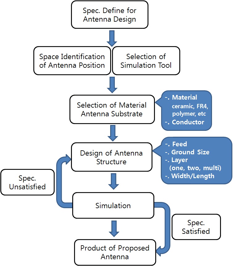
Fig. 2 shows the block diagram of the antenna design process. First of all, we have to define the specification of the antenna design suitable for user needs. Next, we verify the space of the antenna in the system and select the simulation tool. Next, we select the material of the antenna substrate. It is very important to select the material in the antenna design because the antenna substrate heavily affects the antenna performance. Next, we design the antenna structure (feed ground size, layers, etc.) using the antenna simulation tool. If the antenna specifications are satisfied, we can make the simulated antenna from the optimized parameters. However, if the antenna specifications are not satisfied, we carry out a resimulation of the proposed antenna. Finally, we can make the proposed antenna from the optimized parameters satisfied requirement.
>
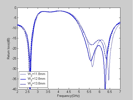
A. Effect of Open-Ended Rectangular Ring, W2
Fig. 3 shows the return loss for different values of length W2. In the 2.4 and 5 GHz bands, it can be seen in the figure that the impedance bandwidth and return loss characteristics did slightly change when W2 was varied from 11.8 to 13.8 mm. It can be seen in the figure, however, that when W2 is 12.8 mm, the return loss characteristics are better than when W2 is 11.8 or 13.8 mm. Also, when W2 is 12.8 mm, the impedance bandwidth satisfied the desired 5 GHz frequency band. Thus, to design an optimal dual-band WLAN operation, W2 was set at 12.8 mm.
>
B. Effect of Gap between Ground Plane and Open-Ended Rectangular Ring, W10
Fig. 4 shows the return loss for different values of length W10. In the 2.4 and 5 GHz bands, it can be seen in the figure that the impedance bandwidth and return loss characteristics did slightly change when W10 was varied from 40.4 to 46.4 mm. It can be seen in the figure, however, that when W10 is 46.4 mm, the impedance bandwidth of the return loss satisfied the desired 5 GHz frequency band. In these cases (W10 = 40.4, 42.4, 44.4 mm), the impedance bandwidth did not satisfy the desired 5 GHz frequency band. Thus, to design an optimal dual-band WLAN operation, W10 was set at 46.4 mm.
>
C. Effect of Inverted L-Strip
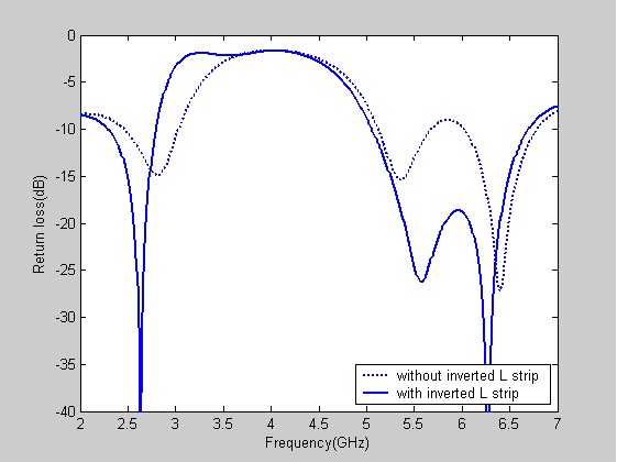
An inverted L-strip was introduced into the open-ended rectangular ring to alter the input impedance characteristics. Fig. 5 shows the return loss with and without an inverted Lstrip in the open-ended rectangular ring. The impedance bandwidth and return loss characteristics worsened when there was no an inverted L-strip in the open-ended rectangular ring. This indicates that the inverted L-strip play an important role in impedance matching of the proposed antenna. The optimal values of the inverted L-strip width (L6) and length (W4) were determined. Thus, to design a good dual-band WLAN operation, W4 was set at 12.0 mm, and L6 was set at 2.0 mm.
>
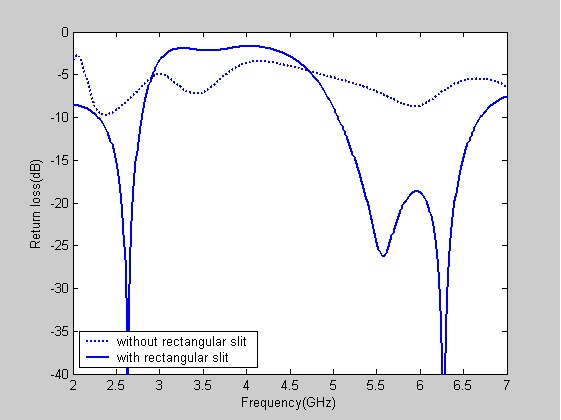
D. Effect of the Rectangular Slit in the Ground Plane
To realize the dual-band WLAN operation, a rectangular slit in the ground plane was introduced into the ground plane to alter the input impedance characteristics. Fig. 6 shows the return loss with and without a slit in the ground. It can be seen in the figure that the resonant frequency was not generated in the 5 GHz bands and that the impedance bandwidth and return loss characteristics worsened when there was no rectangular slit in the ground plane. This indicates that the return loss of the proposed antenna in the 5 GHz bands heavily depends on the rectangular slit in the ground plane. The optimal values of the rectangular slit width (W9) and length (L4) were determined. To design a dual-band WLAN antenna, W9 was set at 4.0 mm, and L4 was set at 10.0 mm. Certainly, with the variation of the width and length in the rectangular slit, the return loss can be controlled at less than return loss -10 dB, thus covering the frequency bandwidth for WLAN (2.4?2.484, 5.15?5.35, and 5.75?5.85 GHz).
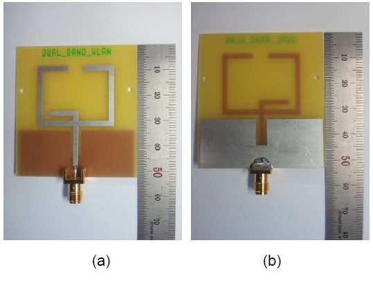
The proposed antenna structure has several design parameters that can handle the resistance and reactance of the antenna input impedance. As such, the dimensions of the proposed antenna were set. as follows: W1 = 32.2 mm; W2 = 12.8 mm; W3 = 2.0 mm; W4 = 12.0 mm; W5 = 13.2 mm; W6 = 14.0 mm; W7 = 2.0 mm; W8 = 21.2 mm; W9 = 4.0 mm; W10 = 46.4 mm; L1= 23.8 mm; L2 = 1.7 mm; L3 = 18.0 mm; L4 = 10.0 mm; L5 = 1.8 mm; L6 = 2.0 mm; L7 = 2.0 mm; L8 = 50.0 mm; and H = 1.0 mm. Based on the design dimensions, the proposed compact antenna was constructed and tested. A prototype of the proposed antenna was fabricated with the aforementioned design parameters and is shown in Fig. 7a and b.
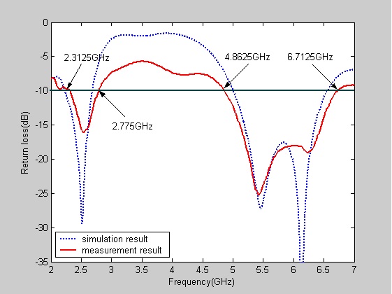
A prototype of the optimized antennas was fabricated and the return loss, radiation pattern, and gain were measured. The frequency response of the return loss of the proposed antenna was measured using an Anritsu MS4644A vector network analyzer at Silla University. Fig. 8 shows the measured and simulated return loss of the proposed antenna for multi-operating wireless communication applications. The results demonstrate that they have a generally acceptable agreement. It can be seen in the figure that a slight difference exists between the simulation and measurement results. This is probably due to the influence of the cable connected to the fabricated antenna in the measurement procedure.
There are two resonant modes that are excited at about 2.5375 and 5.425 GHz with wide impedance bandwidths. The lowest resonant mode has a 10 dB impedance bandwidth of 462.5 MHz (2.3125?2.775 GHz), which covers the 2.4 GHz WLAN bands. The second resonant mode has an impedance bandwidth of 1,850 MHz (4.8625?6.7215 GHz), which satisfies the required bandwidth of the 5.2/5.8 GHz WLAN bands. Clearly, the design prototype of the proposed antenna has sufficient bandwidth to cover the needs of the 2.4 and 5 GHz WLAN bands (2.4?2.484 and 5.15?5.825 GHz, respectively). Theoretically, HFSS was used to evaluate and verify the two resonant frequencies 2.625 and 5.575 GHz, which mainly depended on the lengths of the
open-ended rectangular ring and rectangular slit in the ground plane. As expected, it was obvious that different surface currents were excited by the 2.625 and 5.575 GHz frequencies.
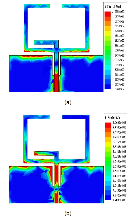
Fig. 9a and b show the surface current density excitations along the open-ended rectangular ring and rectangular slit in the ground plane in the cases of the two resonant frequencies 2.625 and 5.575 GHz, respectively. As shown in Fig. 9a, the 2.4 GHz band surface current density excitations along the open-ended rectangular ring was observed when the resonant frequency was 2.625 GHz. Thus, it can be inferred that the 2.4 GHz band excitation is mainly contributed by the open-ended rectangular ring. As shown in Fig. 9b, however, larger surface current densities flowed not only around the rectangular slit in the ground plane but also along the inverted L-strip when the resonant frequency was 5.575 GHz. Thus, it can be inferred that the 5 GHz band excitation is mainly contributed by the rectangular slit in the ground plane.
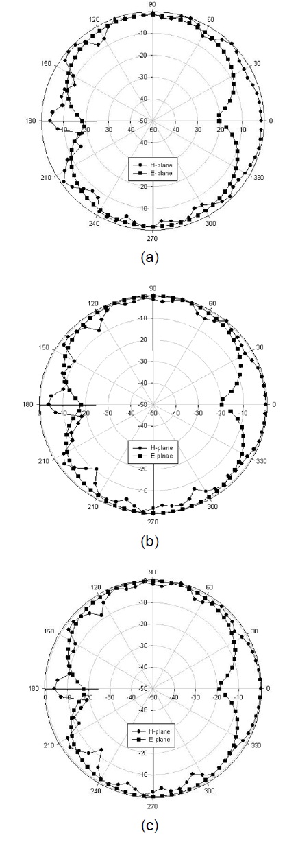
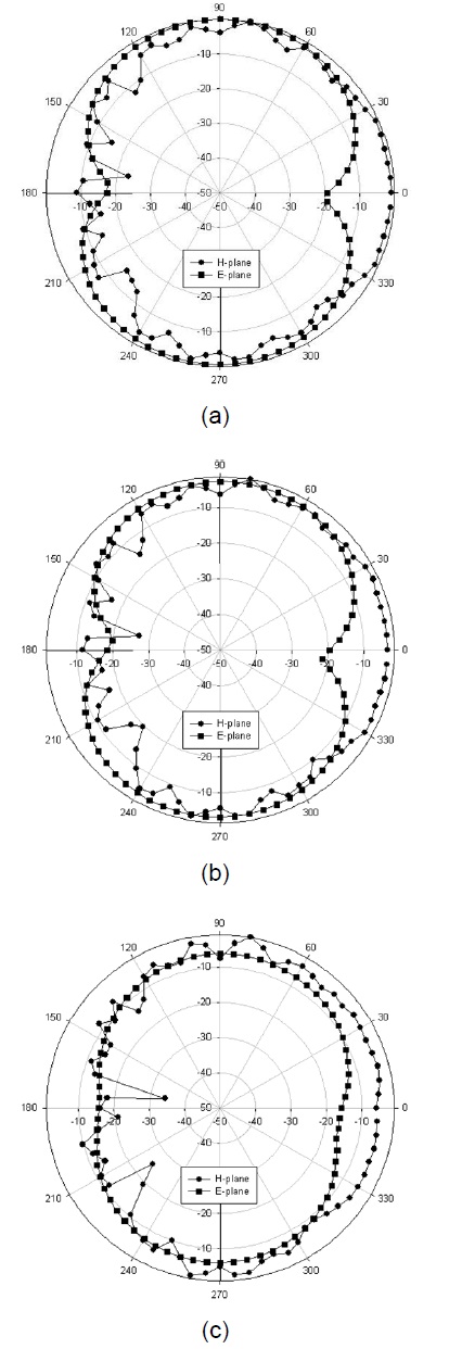
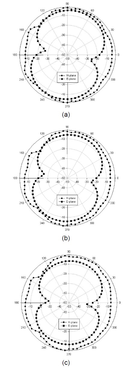
Fig. 10 shows the measured 2D far-field radiation patterns in the E-plane (x-z plane) and H-plane (y-z plane) at 2.4, 2.44, and 2.48 GHz bands. Fig. 11 shows the measured 2D far-field radiation patterns in the E-plane (x-z plane) and H-plane (y-z plane) at 5.15, 5.3, and 5.35 GHz bands.
Fig. 12 shows the measured 2D far-field radiation patterns in the E-plane (x-z plane) and H-plane (y-z plane) at the 5.7, 5.75, and 5.9 GHz bands. From a view of these radiation patterns, the proposed antenna displays omnidirectional radiation characteristics in the H-plane and monopole-like radiation pattern characteristics in the Eplane at the frequencies considered.
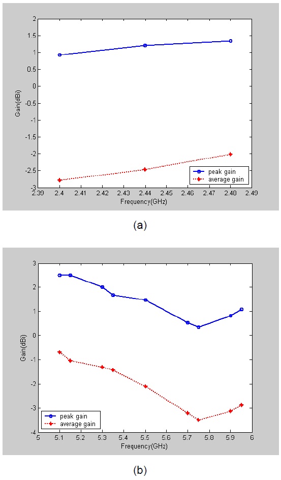
Fig. 13a and b show the 3D measured antenna peak and average gain for the frequencies across the 2.4 and 5 GHz bands. The 2.4 GHz band had an antenna peak gain level of about 0.93?1.33 dBi (Fig. 13a), and the 5 GHz band, about 0.34?2.50 dBi (Fig. 13b). The 2.4 GHz band had an antenna average gain level of about -2.79?2.02 dBi (Fig. 13a), and the 5 GHz band, about 3.50?0.69 dBi (Fig. 13b). The 3D antenna gain had a peak value of 1.20 dBi at 2.44 GHz. At 5.15 GHz, the 3D maximum peak gain was 2.49 dBi; at 5.5 GHz, 1.47 dBi and at 5.9 GHz, 0.82 dBi. As a result, the gain of the proposed antenna within the operating bands satisfies the requirements for WLAN systems.
This article proposed a simple planar monopole antenna for dual-band WLAN operation. With an open ended rectangular ring, inverted L-strip, and a rectangular slit in the ground plane, the impedance bandwidth needed to meet the requirements of WLAN in the 2.4/5.2/5.8 GHz bands were achieved. Various parameters of the proposed antenna were optimized via simulation (HFSS), and tested. Parametric studies of the proposed antenna were conducted, and the mechanisms of the dual-band operation were discussed. This proposed monopole antenna had -10 dB impedance bandwidths of about 462.5 and 1,850 MHz (2.3125?2.775 and 4.8625?6.7125 GHz) or about 18.2% and 31.97%. The experiment results showed that good impedance matching was achieved. Omnidirectional radiation pattern characteristics for frequencies over the WLAN bands were also obtained for the proposed antenna. The proposed antenna’s measured peak gain varied between 0.34 and 2.50 dBi. Because of its low cost, lightweight, and compact size, the antenna is very suitable for WLAN applications. Next, broad and multiband antenna for wireless communication applications should be investigated.