The planetary exploration, that was actively carried out in USA and Russia during the 1960s and 1970s, has been revisited in the 2000s. And in recent years, a number of countries including Japan, China, and India as well as USA, Russia, and Europe invest a large amount of money in the exploration of the Moon and planet, and are actively conducting research on the space development. Especially, the Curiosity, the Mars exploration rover (MER) of National Aeronautics and Space Administration (NASA), recently landed on Mars and is drawing world's attention to the unknown world, Mars. The rover is an important system for unmanned planetary exploration which can easily perform the locomotion to the sample such as rocks and stones designated by the operator, sample collection, and sample analysis on the planetary surface. The current exploration missions of the Moon and Mars are generally focused on collecting the environmental information of Moon and Mars and finding the presence of water and the evidence of life. Especially, the rover is used in numerous missions as it can obtain the in-situ information of the planetary surface. The rover can not only collect the data on the physical, chemical, and mineralogical characteristics of the planet, but also investigate the geological and thermochemical information of the planet and find the important evidence related to the formation and evolution of the planet and solar system. In addition, it is important to find the compounds that include carbon, oxygen, hydrogen, and nitrogen for biologically confirming the presence of water and past presence of life. Therefore, the rover is an essential system of the planetary exploration which has the manipulator (e.g., robotic arm) for scientific sample collection on the planetary surface.
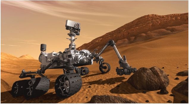
In 1970 and 1973, the lunar exploration rover of the former Soviet Union, Lunokhod, performed the lunar exploration mission as the first unmanned space exploration rover, and in 1971, the Mars rover of the former Soviet Union attempted the Mars exploration though it was not successful. Since then, a number of unmanned exploration rover models were studied and developed, but the MER Sojourner (1997) of NASA, twin rovers Spirit and Opportunity (2004), and the recent Curiosity rover (Fig. 1) are the only ones that were deployed in the practical planetary exploration. In the future, the Mars exploration project of ExoMars rover from European Space Agency (ESA) is scheduled around 2018, and the SELENE-2 program of Japan is planning the
development of the lunar landing module and exploration rover (Micro-5) (Okada et al. 2006).
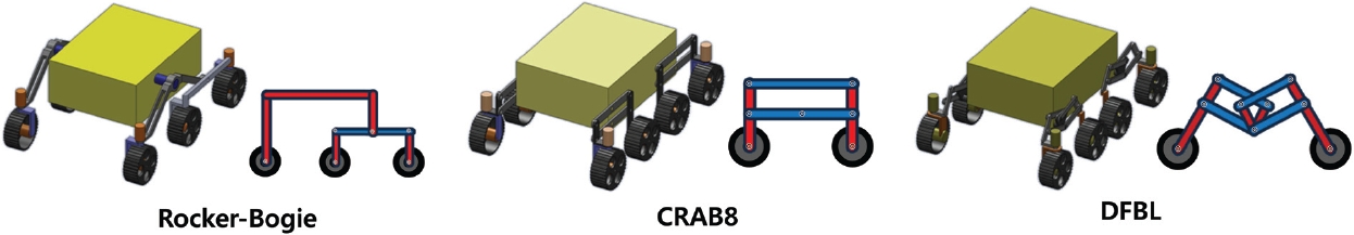
This paper examines the mobility system for the rover ground model necessary to the planetary surface exploration for the benefit of future planetary exploration mission in Korea. In Section 2, the system configuration and design of the overall rover system were described, and in Section 3, the requirements for the rover mobility system development were analyzed and the performance evaluation was carried out for the mechanism of the mobility system based on the shape design and simulation. The proposed 8 wheeled double 4 bar linkage (DFBL) mechanism was compared with the Rocker-Bogie suspension system (Kuroda et al. 1999) of US space agency NASA and 8 wheeled mobility system CRAB8 (Thueer et al. 2006) developed in Switzerland, using the simulation with regard to the stability of locomotion. And in Section 4, the shape design and hardware configuration for the practical rover system construction were illustrated.
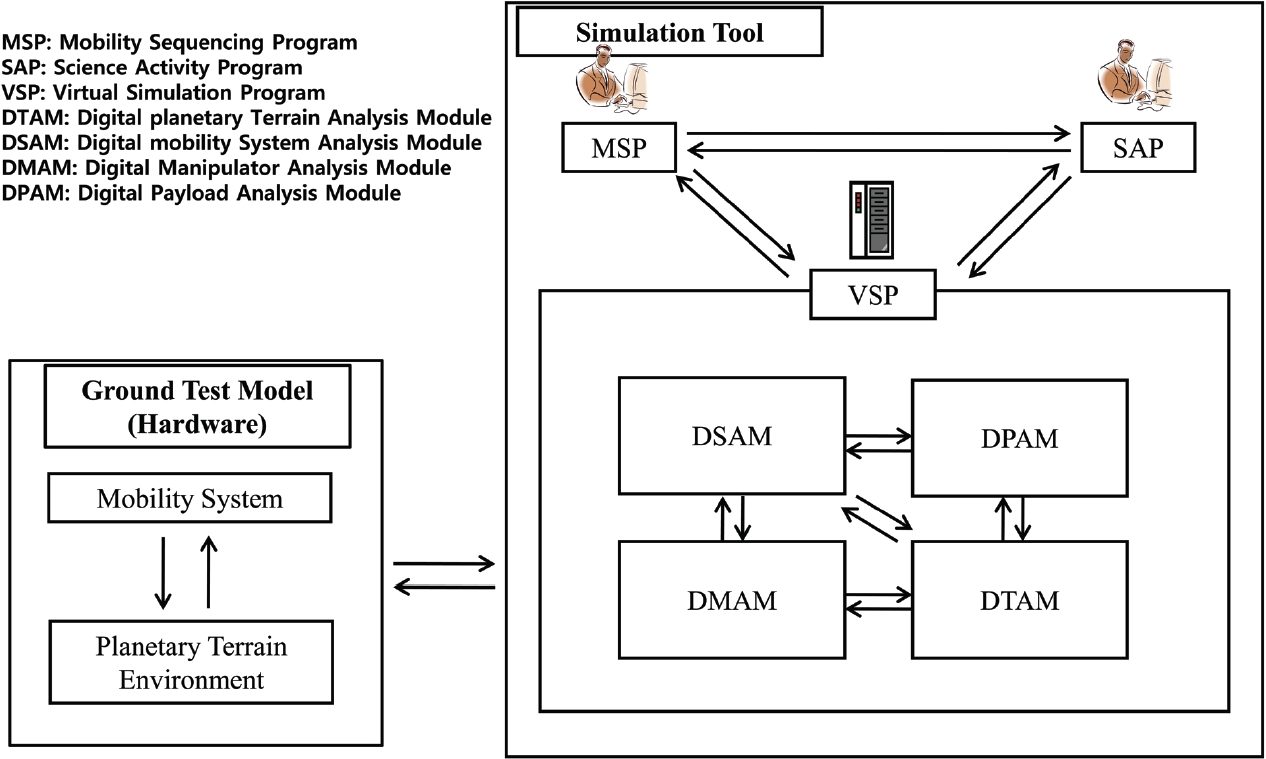
The overall system for the development of the practical planetary exploration rover was designed as shown in Fig. 2. The ground test hardware and configuration of the simulation tool are necessary to develop the practical planetary exploration rovernd test hardware was configured as the test bed which imitates the practical rover system and planetary environment. The simulation tool provides the relevant information to the operator by performing the simulation and prediction analysis of the rover motion at the virtual planetary environment, and it was configured as digital planetary terrain analysis module (DTAM), digital mobility system analysis module (DSAM), digital manipulator analysis module (DMAM), and digital payload analysis module (DPAM). This provides the rover hardware information to the operator and receives the commands from the operator, who determines the mobility sequencing program (MSP) and science activity program (SAP). To perform the practical planetary exploration mission utilizing the rover, a system configuration is necessary as shown in Fig. 2, but this paper will focus on the development of the DFBL rover ground model.
3. DESIGN OF ROVER MOBILITY SYSTEM
3.1 Requirements for Rover Mobility System
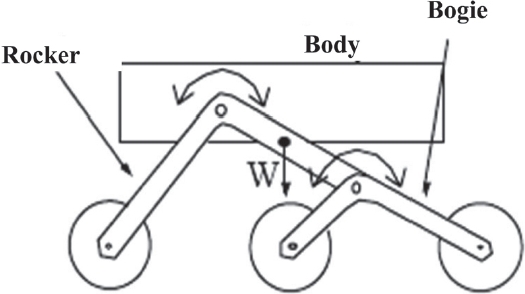
A rover refers to an automated system which can navigate the given environment and terrain, and is one of the most important systems for unmanned space exploration. Among the subsystems of the rover, the rover mobility system is the device that controls the motion of the rover. The rover mobility system determines the performance and stability of locomotion on unknown rough terrain such as Moon and Mars, and a lot of research has been done for the rover mobility system to meet these requirements. Especially, the Rocker-Bogie suspension, which is a passive system, has been applied to the US MER Sojourner, MER, and Curiosity. The Rocker-Bogie suspension system is regarded as a standard in the chassis part of the planetary exploration rover and used for the purpose of the comparison and improvement of the mobility system development in other countries. As shown in Fig. 3, this suspension system has total 6 wheels with a symmetrical structure having 3 wheels on both sides and has the 2 links, Rocker and Bogie, on each side. Both sides are attached together by a differential gear, and this enables the free up and down motion of the wheels and equally distributes the payload on the 6 wheels. Hence, the Rocker-Bogie suspension is an optimal mechanism for climbing obstacles such as rocks, and known to be able to climb obstacles that are 1.5 times the maximum wheel diameter (Kuroda et al. 1999).
Each planetary exploration rover may have different mission, performance and characteristics, but in general, the purpose of the mobility system unit is the safe and stable locomotion on rough terrain such as sand and obstacles. The general and common requirements for the mobility system of the planetary exploration rovers, which have been constructed up to date and are under development, were analyzed. The purpose of this study was to evaluate the mobility and stability of the rover ground model, and therefore only the physical and topographic elements of the planetary environment were examined.
First, the functional requirements for the mobility system are as follows. 1) Travel on plains and slope at the terrain such as rock, stone, and sand, 2) overcome or evade the obstacles such as rock and crack, 3) travel in any directions on the plain surface, 4) detect the obstacles such as rock, crack, and cliff, and inform the operator, 5) travel autonomously by means of the rover sensor-based or map-based mobility algorithm, and 6) travel manually by the command from the operator.
Second, the performance requirements for the mobility system are as follows. 1) Travel in longitudinal and transverse directions at the slope less than 30°, 2) maintain a stable position without overturning at maximum 40° tilt in every direction at a stationary state, and 3) overcome the obstacle that is 120% of the wheel diameter and the crack that is 50% of the wheel diameter.
Third, the characteristic requirements for the mobility system are as follows. 1) Run the rover control S/W, and transmit and receive the data and command, 2) equipped with sensors such as position sensor and acceleration sensor to measure the mobility and tracking error, 3) each wheel has 1 or 2 axle's degrees of freedom and is capable of individual drive, and the part of wheels or the entire wheels are capable of steering, and 4) the bottom surface of the wheel should be designed for minimal slippage during locomotion to maximize the tracking of the command.
3.2 Rover Mobility System Configuration
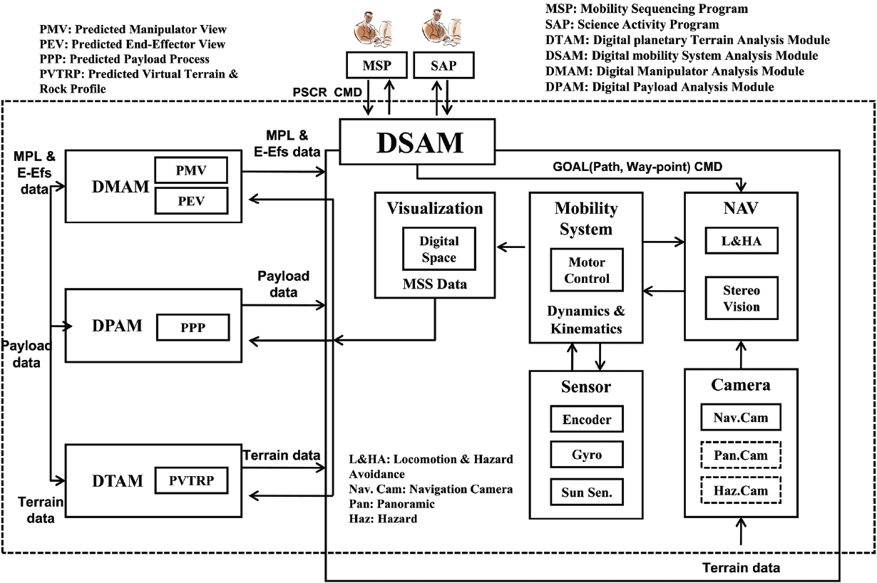
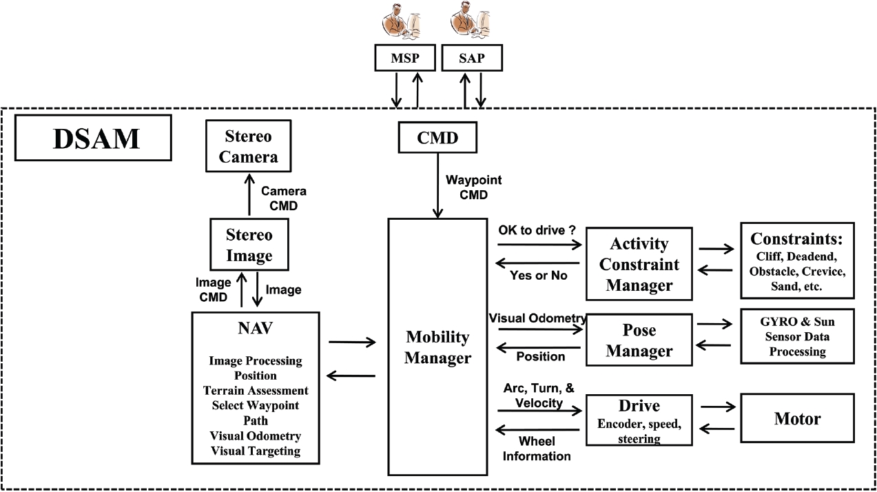
In this section, the configuration and interface of the planetary exploration rover mobility system and the process for operating the mobility system were illustrated. Fig. 4 describes the system interface of DSAM which maintains a close interface with the DMAM, DPAM, and DTAM systems. The DSAM obtains the information from each system and provides the information of DSAM to each system. The DSAM, which is composed of mobility system, navigation system for locomotion, sensors, and camera, extracts the navigation information using all kinds of sensors (e.g., gyro and encoder) and the image data of stereo camera. The navigation information is applied to the wheels and mobility mechanism of the suspension system, and this controls the driving motor for the rover motion. Through this process, the rover is able to arrive at the planned destination.
In term of operating the mobility system, the data and command flow chart can be designed as shown in Fig. 5. When there are no risks detected through the activity constraint manager related with the dangerous obstacles and the pose manager related with the terrain, the mobility manager performs the mobility mission entered by the motor drive following the path command obtained from the data of navigation module which conducts the path setting and image processing of stereo camera. During the practical mobility mission, the wheel torque and steering, center of gravity, wheel friction coefficient, gravity, and the point of contact are entered into the motor drive and as the output data, the wheel encoder and steering angle, mobility mechanism joint angle, and wheel velocity and acceleration values function as the feedback which controls the motion of the rover.
3.3 Rover Mobility System Design
The rover mobility system can be broadly classified as the active and passive types based on the suspension system of the rover (Siegwart et al. 2002). The passive suspension system does not have an additional actuator for stable motion, and simply uses the mechanical structure method. The typical example of the passive suspension system is the Rocker-Bogie which has been applied to the Sojourner of US space agency NASA, MER, and Curiosity. In contrast, the active suspension system refers to the active control that utilizes the close loop control to maintain the stability during locomotion (Siegwart et al. 2002). The active system enables the walking function and therefore has good mobility (e.g., ability to overcome the obstacles) and stability. And the active suspension system has an advantage of minimizing the volume when the rover is carried in a spacecraft because the legs (wheels) of the active rover have more degrees of freedom than that of the passive rover (Kim et al. 2009). On the other hand, the active rover has a higher power consumption and a disadvantage in terms of the reliability because it has a complicated system and requires more devices (Kim et al. 2009).
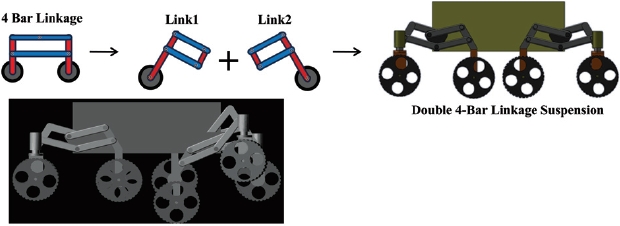
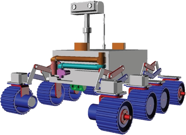
As shown in Fig. 6, the structure of the proposed DFBL rover mobility system is the 8 wheeled passive suspension system which uses the double 4-bar link suspension mechanism where the two 4-bar link were modified and combined. Thoughture is complicated, the system has a symmetrical structure in all directions and shows the same performance when moving forward and backward. An inverted triangle hinge which connects the 4-bar linkage at the front and the back changes the position up and down according to the height of the obstacle, and this in turn changes the position of the wheels up and down according to the height of the obstacle. This passive type link mechanism is easy to control and shows a good performance for overcoming the obstacle. And it can overcome the obstacle that is over 150% of the wheel diameter, and can easily rotate in place and make a curve using the steering motor. As each DFBL suspension system is independently attached, the system is appropriate for rough terrain, and it is easy to load equipments because the center of gravity is located at the center of the rover. As shown in Fig. 6, the structure slightly raises the wheel backward by modifying the link structure, when the front
[Fig. 7.] The trace of wheels for overcoming obstacle (Kim et al. 2011). DFBL: double 4-bar linkage.
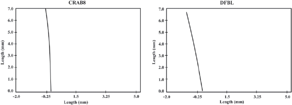
wheel runs into an obstacle. Fig. 7 shows the traces of the first front wheel when climbing over the obstacle for the general 4bar linkage (i.e., CRAB8) and the DFBL whose central link of the front wheel rotates 5° when it encounters an obstacle. The CRAB8 climbs over the obstacle vertically and the DFBL climbs over the obstacle gradually having the front wheel at an oblique angle due to the link structure. When overcoming a stair type obstacle, climbing an obstacle at an oblique angle requires less rear wheel torque than climbing an obstacle in vertical direction.
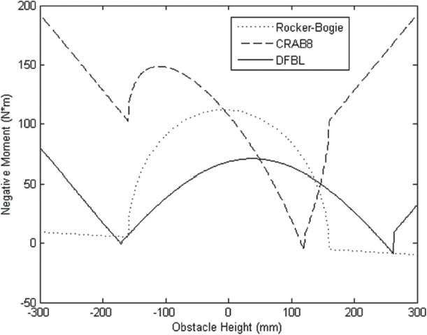
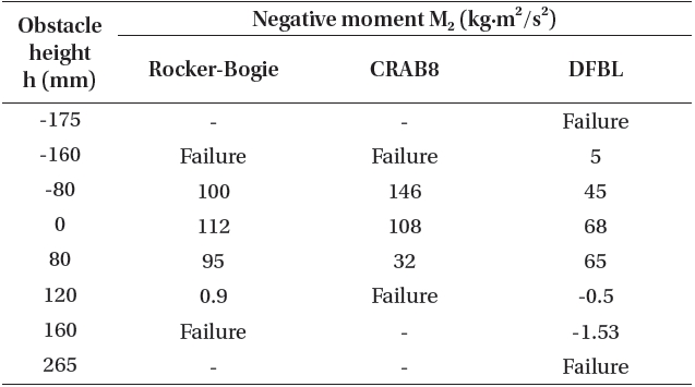
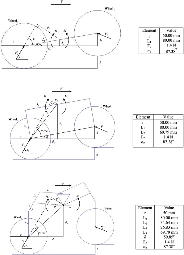
In this section, a simulation was carried out for the effectiveness of the DFBL suspension system to overcome an obstacle. The negative momentum (M2 = ρ2F2) was simulated with the kinematic model of two front wheels at the time of obstacle overcoming for DFBL suspension system, Rocker-Bogie of NASA, and CRAB8 of Thueer et al. (2006) while maintaining the same condition by letting the diameter of the wheels and the length of the links equal, as shown in Fig. 8. The change and size of the negative momentum depending on the size of the obstacle was the smallest for the DFBL as indicated by the results in Table 1 and Fig. 9. This suggests that the DFBL can overcome
[Table 1.] Simulation result of the negative moment.

Simulation result of the negative moment.
the obstacle more easily compared to other structures on general terrain requiring less power consumption.
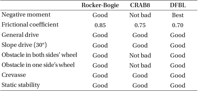
For the performance comparison of DFBL depending on various locomotion environment, the Rocker-Bogie suspension system of NASA and CRAB8 suspension system were modeled to have the same physical properties using a 3D model as shown in Fig. 10, and the simulation was carried out for the requirements presented in Section 3.1 such as basic locomotion, obstacle overcoming (obstacles on both wheels and obstacle on a wheel), locomotion on the slope, static stability, and crack overcoming. The simulation results summarized in Table 2 shows that all of the three suspension systems have outstanding performance for basic locomotion, locomotion on the slope, static stability, and crack overcoming with little difference. However, they showed a difference in the obstacle overcoming performance. First, the simulation was performed for the friction coefficient necessary to overcome the stair
type obstacles on both wheels that are 150% of the wheel diameter for each suspension system. The simulation measured the friction coefficient necessary to overcome the obstacle by applying the same friction coefficient to all the wheels. The friction coefficient of DFBL was 0.70 which is the smallest, that of CRAB8 was 0.75, and that of Rocker-Bogie was 0.85. The smaller friction coefficient indicates that the obstacle can be overcome with the smaller frictional force between the ground and wheels, and that the obstacle overcoming performance is superior.
[Table 2.] Performance simulation results of rover’s mobility system.

Performance simulation results of rover’s mobility system.
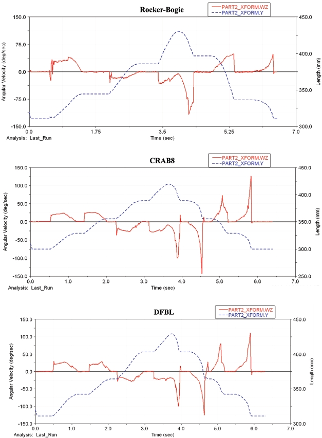
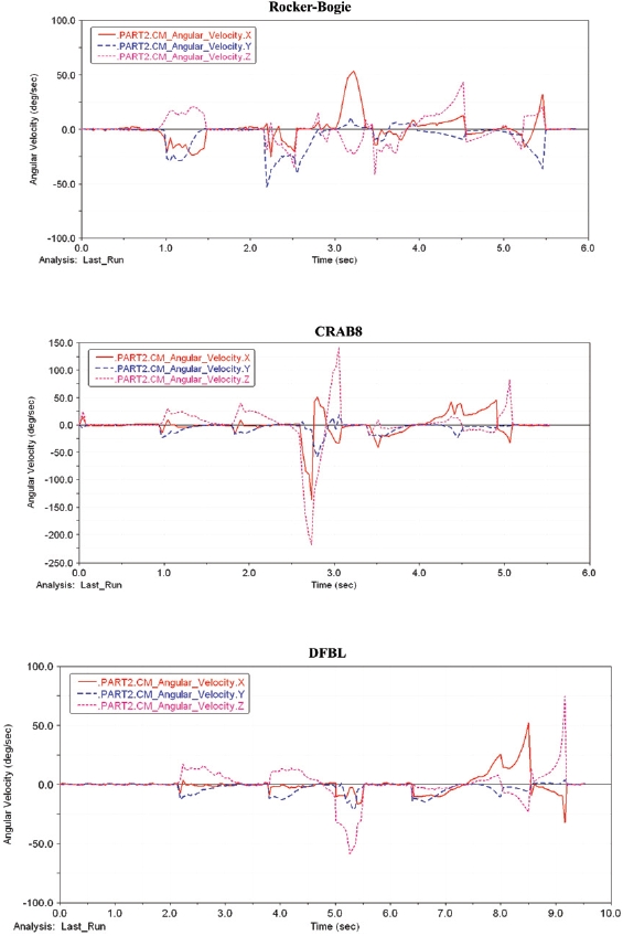
And the simulation was performed for obstacle overcoming with the stair type obstacles on both wheels of the each modeled suspension system that are 120% of the wheel diameter, 100 mm, and Fig. 11 shows the results. The blue dotted line, which corresponds to the right axle, represents the location of the center of gravity for the rover and obstacle overcoming process of the rover. The red line represents the angular velocity of the robot body and the smaller variation indicates more stable obstacle overcoming of the rover. As shown in the graph, the CRAB8 and DFBL have slightly higher angular velocity of the body compared to the Rocker-Bogie at the time the rover descends the obstacle. The angular velocity variation of DFBL was about 125 deg/sec, that of CRAB8 was about 140 deg/sec, and that of Rocker-Bogie was about 115 deg/sec. This suggests that the CRAB8 is the most unstable compared with other robots. And in the case of the Rocker-Bogie, vibration occurs in the section that the front wheels overcome the obstacle at the time the robot meets the obstacle. This indicates that the Rocker-Bogie requires a bit more time for obstacle overcoming compared with other two suspension systems.
Another simulation was performed for the shaking of the body relative to the X, Y, and Z axes with the stair type obstacle on a wheel that is 120% of the wheel diameter, 100 mm, and Fig. 12 shows the results. In other words, based on the center of gravity for the body, it measures the angular
velocity relative to the X, Y, and Z axes as time passes, and a larger variation indicates unstableness. As shown in the graph, the DFBL rover and Rocker-Bogie overcame the obstacle rather stably and the CRAB8 overcame rather unstably. The CRAB8 requires a larger torque for stable obstacle overcoming compared to the DFBL rover and therefore shows the unstable angular velocity when the same torque is applied as in the simulation of Fig. 12.
As demonstrated by the simulation results, the ground model operated by the DFBL mechanism showed a better performance for the obstacles compared to the CRAB8 which has the basic 4-bar link mechanism, and the performance of the DFBL mechanism for overcoming the high obstacles with less frictional force using the large traction power of 8 wheels was superior to the Rocker-Bogie. Table 2 summarizes the simulation results on the mobility performance (e.g., obstacle overcoming) described in this section.
Based on the simulation results of the Section 3, the shape design of the rover was developed for the rover system construction as shown in Fig. 13. The size of the entire body was designed to be 49 × 58 × 24 cm3 excluding the camera pole unit at the top, and the drive unit is composed of total 8 drive wheels with 4 sets of DFBL suspension system according to the mobility system design of Section 3, and the diameter and width of the wheels were designed to be 10 cm to increase the stability of locomotion for the obstacle overcoming. In the drive unit, each wheel is equipped with drive motor and steering motor, and has 2 degrees of freedom.
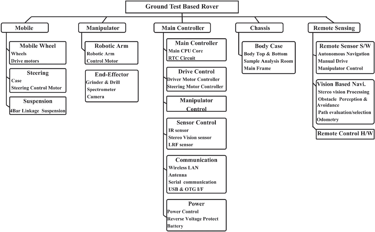
Fig. 14 outlines the system for the rover ground model construction, and the rover ground model is broadly composed of the mobility system, manipulator, main control unit, body unit, and remote sensor unit. The mobility system consists of the suspension system, wheel unit, and steering unit, and the manipulator consists of the robotic arm and terminal scientific instrument. The main control unit is comprised of the sensor, communication, and electric power systems for rover mobility and manipulator control, and the remote control unit is comprised of the software for rover mobility and manipulator control.
In other words, the rover is made up of main controller and motor controller which serve as the interface for the motor information and motor control command. The rover is controlled by the operator through the development of the remote controller which operates the rover and displays the rover condition information for the operator. The motor controller interfaces with the mobility motor and steering motor of the drive unit and the manipulator control motor of the manipulator. The motor controller delivers the control
command of the operator through the remote controller and main controller and informs the operator about the condition of each motor through the main controller and remote controller. The main controller interfaces with the infrared sensor, laser range finder (LRF), and stereo vision sensor. The main controller informs the operator about the distance information for detecting the crack and cliff from the infrared sensor, obstacle distance and location information from the LRF, and image information from the stereo vision sensor through the remote controller via radio communication. The remote controller delivers the control command of the operator to the main controller through the remote monitoring GUI program and displays the overall rover condition information.
The purpose of this study was to enhance the overall understanding of the rover system which is essential for the Korea-led planetary surface exploration in the future. The rover, which is critical for unmanned planetary exploration, should guarantee a stable mobility for performing the locomotion to the exploration target of the planetary surface designated by the operator and sample collection and analysis. Therefore, a new DFBL mechanism was proposed which consists of the passive suspension system with 8 wheeled DFBL and the superiority was demonstrated with respect to the stability of locomotion compared to other suspension systems through the performance evaluation for the mechanism of the mobility system based on the shape design and simulation. In addition, the requirements for the rover were analyzed and the system configuration was developed. Hence, this paper will improve the overall understanding of the planetary exploration rover system through the analysis of the performance requirements for the mobility system and the design of the mobility system, which is applied to the rover ground model.