The Attitude Determination and Control System (ADCS) is to stabilize the spacecraft against attitude disturbing influences resulting from the environment in the Earth’s orbit in order to orient it in the desired fixed pointing. Active control of the attitude of a satellite can be achieved by a number of different actuators: reaction wheels, thrusters, control moment gyroscopes or magnetic torquers. However, the magnetic torquers are widely used actuators for geostationary satellites, small satellites, and microsatellites. These high-tech devices interact with the Earth’s magnetic field and create a control torque, which can be adjusted to the required value. Combined with one or more reaction wheels, they provide all the control you need to maintain your spacecraft’s attitude [8] and [14].
Unlike thrusters, magnetorquers are lightweight, reliable, and energy-efficient. A further advantage over momentum wheels and control moment gyroscopes is the absence of moving parts and therefore significantly higher reliability. However, they require a thoughtful design and careful assembly.
The main disadvantage of magnetorquers is that the strength of the magnets should be chosen to be strong enough to overcome the greatest expected disturbances (as given in table 1). A broader disadvantage is the dependence on Earth's magnetic field strength, making this approach unsuitable for deep space missions, and also more suitable for low Earth orbits as opposed to higher ones like the geosynchronous. The dependence on the highly variable intensity of Earth's magnetic field is also problematic since the attitude control problem becomes highly nonlinear. It is also impossible to control attitude in all three axes even if the full three coils are used, since torque can only be generated perpendicular to the Earth's magnetic field vector [11] and [13].
The main issue of this work is to investigate the feasibility of using a medium power (5kw) to produce a torque on low Earth orbit cubesats in order to overcome some disadvantages of the traditional attitude actuators. The use of a ground based laser to produce a perturbing force goes back to the study of laser orbital perturbations by some scientists. The use of this medium power has the advantage of being inexpensive, and suffering a less amount of atmospheric attenuation. Moreover, it is safe in use where it cannot damage the satellite surface [3], [10] and [6].
[Table 1.] Worst-case expected disturbance torques for a 1-U CubeSat at 700 km [11]

Worst-case expected disturbance torques for a 1-U CubeSat at 700 km [11]
The laser intensity delivered to the satellite surface is determined using an analytical model of long range laser beam propagation through the atmosphere. For standard atmospheric conditions, this model considers only the linear mechanism of laser atmospheric interactions. Moreover, the atmospheric turbulences are countered by using the adaptive optics and technical capabilities of the laser system. Based on that model, the laser intensity is proportional to the laser power and inversely proportional to satellite altitude and laser divergence. The laser intensity is given by [2] and [10]:
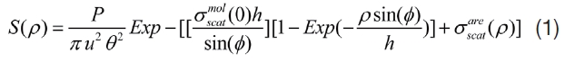
where, u is the satellite altitude,

is the molecule scattering coefficient at sea level,

is the aerosols scattering coefficient and is the sea level altitude.
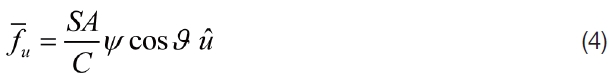
The total radiant force exerted on a flat non-perfectly reflecting surface is given by [9]:
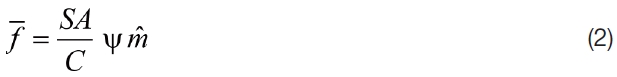
where,
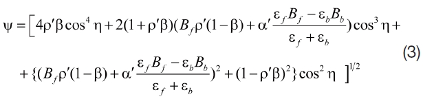
where

is a unit vector directed through the force direction, c is the speed of light and S is the radiation irradiance at the debris surface,
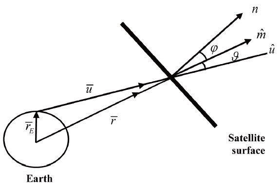
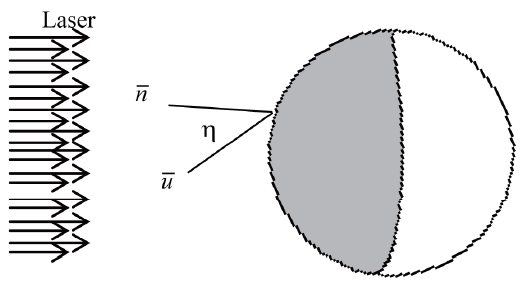
For non-perfectly reflecting surfaces, The force vector,
, is not directed normal to the surface. But, it inclines by an angle

as depicted in figure 1. So, the force components in the incident direction will be:
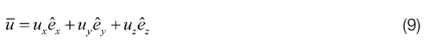
The geocentric equatorial system is used with the unit vectors;

directed parallel to the Earth equatorial plane,

directed in the plane that contains the meridian of the sub-satellite point and

directed normal to the equatorial plane. As shown in Fig. 1, the incident radiation vector,

given by:

where

is the satellite position vector and

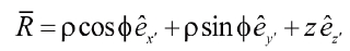
is the Earth radius vector (station coordinates) . For an oblate Earth, the Earth radius vector is given by [4]:
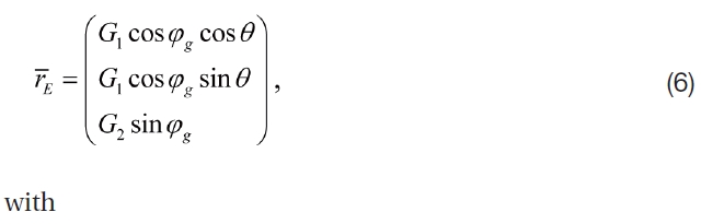
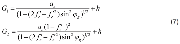
where
The satellite position vector,
in the geocentric coordinate system, is given by [4]:
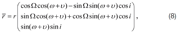
with
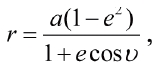
where Ω is the longitude of the ascending node, ω is the argument of perigee,
with


The radiation torque,

acting on a spacecraft is given by
the general expression [1], [14] and [15]:

where

is the vector from the spacecraft'scenter of mass to the element of the satellite projected area
acting on a spacecraft is given by:

For a high laser repetition rate, many laser shots fire toward the satellite over an interval of time each one of intensity S. Consequently, the laser force can be considered as a continuous function. Thus, the total laser torque over an interval of time,
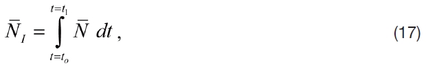
where
In order to evaluate the previous integrals, the vector
must be determined. So, satellite geometry must be considered. In the next sections, three particular cases; circular cylindrical satellite, spherical satellite and satellite of complex shape will be studied.
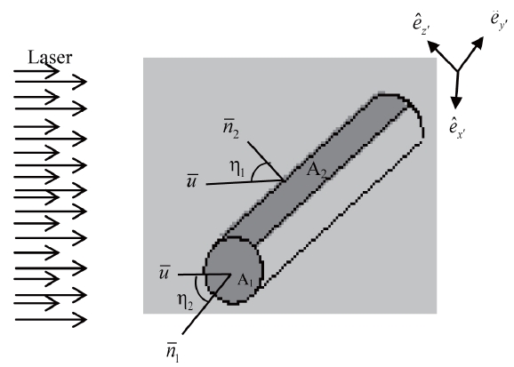
2.5 Laser Torque Applied on Circular Cylindrical Satellite.
The position vector of the surface elements can be expressed in terms of a coordinate system with unit vectors
where its origin
is at the geometric center of the satellite, as follows:
where
can be transformed into the following geocentric coordinate:
with


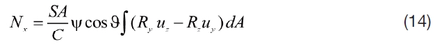
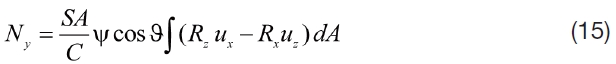
The illuminated surfaces of the cylinder satellite are a circular flat surface of radius ρ and an area
Substituting into eqs. (14-16) and integrating over the areas
2.6 Laser Torque Applied on Spherical Satellite.
The position vector of the surface elements can be expressed in terms of a coordinate system with unit vectors
where its origin
is at the geometric center of the satellite, as follows:
where ρ is the radius of the sphere, ? is the polar angle and ? is the azimuthal angle. The position vector,

can be transformed into the following geocentric coordinate:
with


The illuminated surfaces of the spherical satellite can be considered as a hemisphere with an area
Substituting into eqs. (14-16) and integrating over the area A, the laser torque applied on a spherical satellite is obtained.
2.7 Laser Torque Applied on Satellite of complex shape.
In order to compute the torque applied on spacecraft of complex shape, we can follow the following scheme [5] and [7]:
1-Approximate each surface by means of simple geometric shapes (planes, cylinders, cones, spheres,…, etc.).
2-Determined the torque applied on each surface independently.
3-Then, the total torque applied over the whole spacecraft is obtained by the vector sum of all torques applied on each elementary surface.
Based on the standard atmospheric conditions and taking into consideration that
and
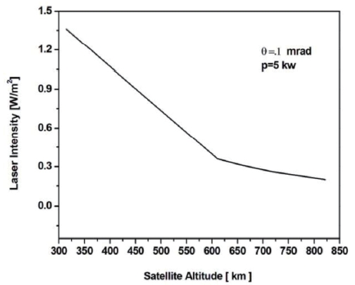
In case of clear weather conditions, the propagation of a medium-powered 5 kW ground-based laser with a divergence of .1 mrad is illustrated in the following figure:
As illustrated in fig 4, the laser intensity has a significant dependency on the altitude. It has a maximum value ~1.4W/ m2 at the altitude of 314.4 km. However, it has a minimum value ~0.2W/m2 at an altitude of 823 km.
In the present work, the laser torque applied is calculated under the following postulates:
1-The laser source is located in the Helwan SLR station in Egypt with latitude of 29.86° N, longitude of 31.34° E and elevation of 145.46 m.
2-The radiation falls normal to the satellite surface (i.e.
3-The satellite surface is made of Aluminium, so it can be considered as a perfectly reflecting surface. Therefore, the laser force will be duplicated, where the satellite surface specularity
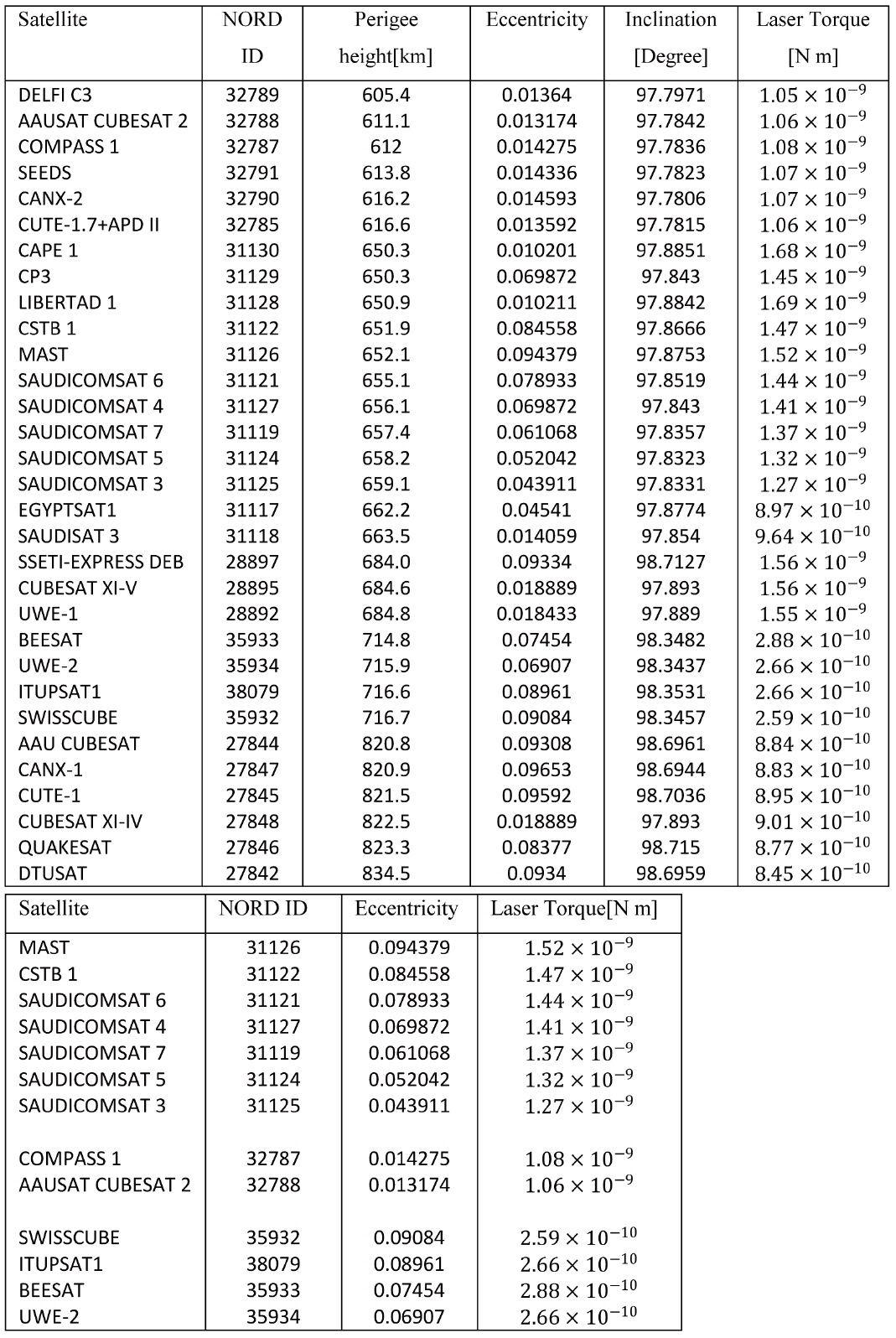
Based on the previous postulates and for a given time, the torque produced by a 5 kw laser beam is calculated for some

laser torque affecting on LEO cubesats at different altitudes using 5 kw laser beam at a given time.
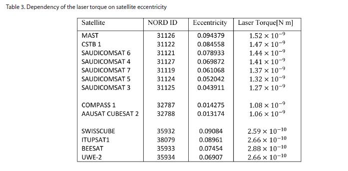
[Table 3.] Dependency of the laser torque on satellite eccentricity
Dependency of the laser torque on satellite eccentricity
low Earth orbit cubesats and the results are illustrated in the following table:
As illustrated in table 2, the satellites are arranged in ascending order according to their perigee height as it is clear in the table that the laser torque depends on the latitude, since the radiation force is inversely depended on the satellite altitude. The laser torque has a maximum value in the order of for a cubesat with a perigee height close to 600 km, however, it has a minimum value in the order for a cubesat perigee height close to 800 km.
In addition to the satellite height, the dependency of the ground based laser torque on the orbital eccentricity is studied and illustrated in table (3).
As illustrated in table 3, the satellites are chosen to be nearly of the same altitude and inclination and they are arranged in descending order according to their eccentricity as it clear in the table that the laser torque directly depends on the orbital eccentricity.
A simple model of radiation torque affecting on satellites of various shapes is formulated using the geocentric equatorial coordinate system. Based on the model, the intensity delivered to the target is proportional to the laser power and inversely proportional to the beam divergence as given by eq. 1. So, we can adjust the laser power and divergence (by choosing the beam wavelength) in order to obtain the required control torque.
The current numerical test confirms that the laser torque has significant contribution on the low Earth orbit cubesats. The results show that the laser torque has a maximum value in the order of 10-9 which is comparable with that of solar radiation. However, it has a minimum value in the order of 10-10 which is comparable with that of the gravity gradient. Moreover, the laser torque depends directly on the orbital eccentricity whereas when the orbit becomes more circular it will experience less torque. Therefore, we can conclude that the laser torque can be used as an active attitude control system for cubesats.

![Worst-case expected disturbance torques for a 1-U CubeSat at 700 km [11]](http://oak.go.kr/repository/journal/11787/HGJHC0_2012_v13n4_484_t001.jpg)