Over the past few years there has been a growing need and demand for medium-altitude, long-endurance aircrafts. Medium-altitude, long-endurance aircrafts, abbreviated in the present paper as MALE aircrafts, are designed for longrange and long-endurance intelligence and surveillance purposes. For instance, MALE aircrafts are suited to execute a broad range of intelligence and surveillance-related tasks, including monitoring environments for nuclear or chemical contamination, target acquisition, reconnaissance missions, aerial refueling, strategic missile defense, cellular telephone relaying, meteorology, weather forecasting, and numerous others. When compared to other aircraft, the use of a MALE aircraft affords great advantages in the execution of these and other related tasks. The many assets of a MALE aircraft are largely the product of its design; for instance, MALE air vehicles are generally smaller than most other manned air vehicles and accordingly cost less to operate, as fuel and hangar costs are much lower. Moreover, the expenditures that are related to the human factor are minimal. As an illustration, the interior of the unmanned aircraft is optimized since it does not require any seat or complex instruments’ panel given that these aircraft do not carry human operators. In summary, the everincreasing use of MALE aircraft for a wide array of purposes throughout the world has elevated the analysis of all aspects of this aircraft to an endeavor of utmost importance.
One of the most distinguishing features of MALE aircraft design is the incorporation of high aspect ratio wings. Similarly to innovations in fixed and rotary wing aeroelasticity, the study and novelties in high aspect ratio wings has increased dramatically in the past few decades. However, whereas the study of fixed and rotary wing aeroelasticity heralded the publication of several review articles and studies in the field [1-2], the literature on MALE aircraft remains minimal. In other words, there is no open literature available on MALE aircraft with high-aspect ratio wings. Hence, Van Schoor, et al., has analyzed the aeroelastic properties of high-altitude, low-endurance (HALE) unmanned air vehicles with high aspect ratio wings [3]. The authors endeavored to study and account for the aeroelastic characteristics and the control of these highly flexible aircraft. Previous investigations in this field employed linearized modes, including rigid body modes, to predict the stability of the aircraft under different flight conditions. Through these studies, it was concluded that unsteady aerodynamics, combined with the flexibility of the aircraft, provided a better correlation. Nevertheless, the importance of the geometrical nonlinearity in HALE aircrafts was highlighted later; see [4,5and6]. The above-mentioned works have concluded that the linear analysis based on the undeformed shape may not be accurate in the case of HALE aircrafts with high aspect ratio wings. Furthermore, in reference [7], investigations were carried out to explore the effects of the large payload-induced deformations and the effects of the parameters of the fuselage and horizontal tails on the flight dynamic characteristics of a highly flexible aircraft. Another key point of this work to undertake here means to account for or to investigate in sensitivity of some aeroelastic characteristics upon altering configuration parameters. This increased sensitivity was identified to be the result of the strong coupling of the highly flexible structure and aerodynamics. Given these points, for highly flexible aircrafts such as MALE aircraft, the coupled effects of large deflection due to structural flexibility and flight dynamics (e.g., roll controllability) as well as other aeroelastic effects (e.g., gust response, flutter instability) must be properly accounted for by applying a nonlinear aeroelastic formulation.
In this paper, an aeroelastic analysis of the high aspect ratio wings of a MALE aircraft will be developed and validated. These aircrafts are able to effectively perform medium-altitude, long-endurance surveillance missions largely because of their structural design. Chiefly, the long and slender wings of these vehicles are able to maximize the lift-to-drag ratio. At first, the cross-sectional inertia and stiffness properties will be extracted using the Variational Asymptotic Beam Sectional Analysis (VABS) [8]. With this in mind, the free vibration analysis will be carried out and natural frequencies will be obtained. Hence, the aeroelastic response analysis will be performed with the first few modes. In the meantime, a MALE aircraft may also undergo large deformations under normal operating loads leading to a geometrically nonlinear behavior. In view of that, the nonlinearities will be considered in the next stage of this research. For instance, a nonlinear model would facilitate the study of other important aspects of a MALE aircraft such as the trim effect. In addition to that, the next phase will also comprise investigations on the effects and inherent consequences of the inevitable interaction between rigidbody flight dynamics and aeroelastic modes.
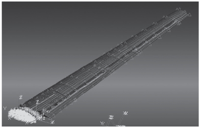
The analysis that has been carried out examines and considers the properties of one-dimensional beams. In order to do so, a structural model of an Euler-Bernoulli beam, which is a displacement-based beam, was created in order to investigate its various structural properties. The linear behaviors of these high aspect ratio wings and the behavior of these flexible wings under unsteady subsonic aerodynamic forces were investigated [9]. First, the degrees of freedom had to be defined. Next, mass and stiffness matrices were obtained from the minimum energy kinetic principle. The structural analysis results of the present beam model were validated with the three-dimensional NASTRAN result. Figure 1 shows the three-dimensional finite element wing construction. It has two control surfaces. Structurally, the stiffness of the Euler-Bernoulli beam is the result of its composite materials.
This section was written exceptionally well. It was clear and concise.
The flutter matrix equation is derived in the Laplace domain in terms of the generalized mass matrix,
(1) and (2).

This can be rewritten as:
The K-Method
The basic equation for flutter analysis by the K-Method is:

It is obtained by replacing by
Where
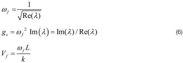
The K-Method equation can be obtained by substituting Eq. (4) into Eq. (3) and dividing the resultant equation by
Where
is the complex eigenvalue of Eq. (5).
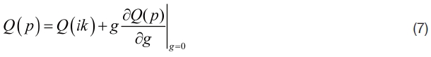
To solve for these eigenvalues, unsteady aerodynamic computations must be conducted at several reduced frequencies. These reduced frequencies are defined here as the “reduced frequency list”.
The flutter frequency
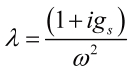
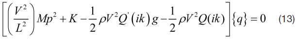
The G-Method
The G-Method is a damping perturbation method It means that this method is based on damping perturbation. (Ed. note: This is unclear. Do you mean, ‘a method based on damping perturbation’? Please confirm). It includes a first order damping term in the flutter equation.
This first order term is rigorously derived from the Laplace domain aerodynamics. In the G-Method, it is assumed that a function of
This premise is based on the fact that the Laplace transform of the time domain unsteady aerodynamics for divergent
The term

in Eq. (7) is not available in the K-Method. However, if
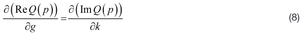
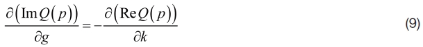
Combining Eqs. (8) and (9) leads to the following general condition:
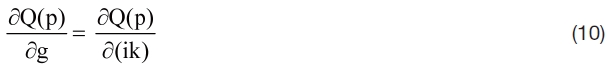
Equation (10) is valid in the complete p-domain except along the negative real axis where discontinuity due to a branch cut in subsonic flow occurs.
Thus, the term
can be replaced by:
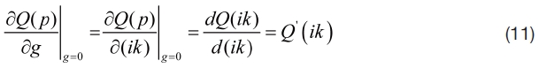
Since
Substituting Eq. (11) in Eq. (7) gives the approximated p-domain solution of in terms of

Substituting Eq. (12) in Eq. (2) yields the G-Method equation:
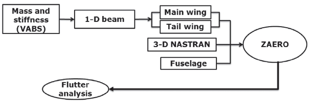
In order to analyze the main wing of the aircraft, mass and stiffness matrices were first obtained from the crosssectional analysis performed by VABS [8]. Afterwards, an evaluation of the structural model of the Euler-Bernoulli beam allowed obtaining the relevant mode shapes and natural frequencies of the beam. These properties, as well as the newly-obtained system matrices, were further analyzed and adapted in order to be properly implemented in ZAERO (See Figure 2). To analyze the aeroelastic stability of the one-dimensional beam, .FRE files were built and used in ZAERO DLM. Similarly, the three-dimensional NASTRAN model supplied the .F06 files that were utilized for the flutter analysis. The latter was considered as a reference to validate the one-dimensional beam model.
2.4 Complete Aivrcraft Analysis
For complete aircraft configuration, the assemblage combination of multiple beams was considered. As for the main wing, both mass and stiffness properties were obtained throughout the dimensional reduction carried out by VABS; which constitutes a tool that enables an efficient high-fidelity cross-sectional analysis. Next, the free vibration analysis results for both main and tail wings were achieved from the one-dimensional beam analysis. Later, this outcome was combined with the properties of the fuselage (See Figure 3). Upon compiling all the data, ZAERO was employed to perform the flutter analysis, the results of which were again compared with those obtained by the three-dimensional finite element model.
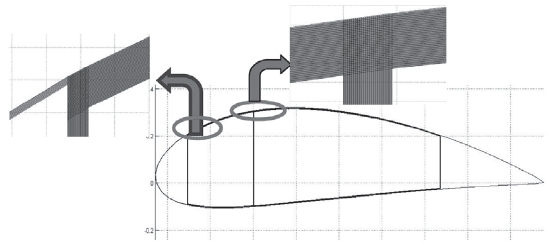
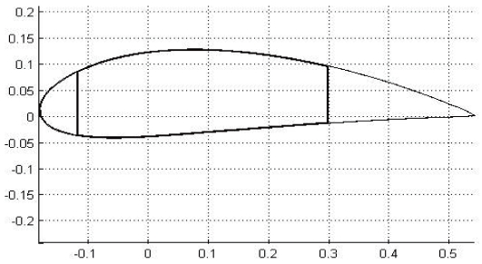
VABS produced a modeling of the cross-section for the high aspect ratio wing. For instance, VABS implements a rigorous dimensional reduction from the three dimensional description to a one-dimensional model [8-9]. The crosssection of a high aspect ratio wing is presented below (See Figure 4). The inertial and stiffness properties will be presented in the numerical results.
Based on the main three-dimensional NASTRAN model, a more detailed representation of the finite elements for each of the aircraft’s components is depicted. Further geometric and structural properties that are determined through the use of the NASTRAN model are placed into corresponding tables and figures. All one-dimensional results have been compared to the corresponding three-dimensional NASTRAN results, the latter of which is considered to be a more accurate representation of the actual geometrical and structural data of the aircraft.
The results of this study will start with the present crosssectional analysis using the active twist rotor (ATR) blade data [11], and the aeroelastic analysis of the MALE UAV wing. In the three-dimensional NASTRAN model, a taper ratio of 0.5 was applied. This is based on the MALE model that has
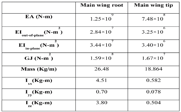
[Table 1.] Cross-sectional analysis results

Cross-sectional analysis results
[Table 2.] Natural frequencies of the single main wing
Natural frequencies of the single main wing
[Table 3.] Natural frequencies of the single tail wing

Natural frequencies of the single tail wing
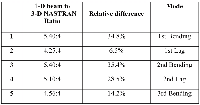
[Table 4.] Comparison upon the natural frequencies of the single main

Comparison upon the natural frequencies of the single main
been used throughout this study, which is comprised of 21 ribs and 3 spars. For the structural analysis, approximately 1,000 grid points are applied.
Using the obtained stiffness and mass properties, the free vibration analysis is carried out and natural frequencies are acquired for both the ATR blade and the MALE UAV wing. The relevant natural frequencies are obtained from a displacement-based formulation (linear) and MSCNASTRAN model (three-dimensional) for the ATR blade [12].
Further analysis is then performed which aims to determine the correlation between the one- dimensional beam model and the three-dimensional finite element model results in terms of mode shapes and natural frequencies. To begin with, the stiffness and mass results obtained from the three-dimensional NASTRAN model are used as inputs within VABS which implements a significant dimensional reduction. The details of the cross-sectional geometry and material properties are then included as inputs, allowing the existing beam models to be considered as well.
This table description is very well written. It is quite evident at this point that the paper is of high written quality as few revisions have been needed.
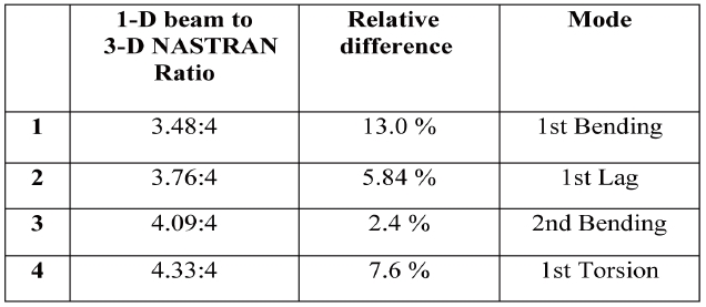
In Table 2, the structural analysis results of the onedimensional beam are presented. In terms of natural frequencies, the one-dimensional beam demonstrates unsatisfactory correlation with the three-dimensional model illustrated by the significant relative difference in terms of the natural frequencies.
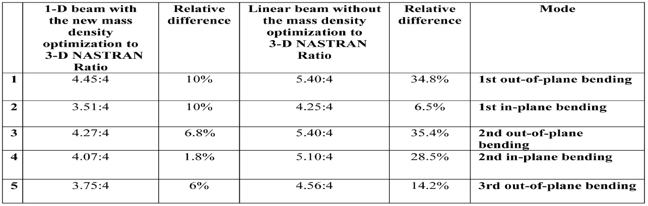
It was then concluded that the differences obtained in both mode shapes and natural frequencies might be due to the assumption made at the very beginning of this structural analysis. To clarify, the same mass distribution as the one used throughout the three-dimensional finite elements model was also used for the one-dimensional beam analysis. In other words, the implementation of these mass properties throughout VABS was attempted before performing the one-dimensional beam analysis. Consequently, this was suspected to be the cause of the differences noted in the previous results. For that purpose, an iterative procedure has been introduced and used for a more relevant mass distribution. For instance, this iterative procedure was applied based on a new optimized mass density distribution. The results obtained through this new approach show increasingly similar solutions between the one-dimensional beam and the three-dimensional model. A comparison between the previous one-dimensional model and the revised one is provided in Table 4. It can be seen that the relative difference between the new one-dimensional model and the three-dimensional finite elements model is diminishing.
The obtained results indicate that the effect regarding the number of ribs on the mode shapes, natural frequency
and the flutter speed are quite marginal. Therefore, it can be concluded that changing the number of ribs does not influence the natural frequencies or the flutter speed in any way. Likewise, changing the spars would influence the bending and torsion frequencies in addition to the flutter speed.
In summary, from a three-dimensional elasticity description to a one-dimensional continuum model, all the details regarding the cross-sectional geometry and material properties are included as inputs to calculate both structural and inertial coefficients. Later, these properties can be directly imported into the one-dimensional beam analysis to predict the global behavior of the wing. In fact, this imported data is necessary for predicting point-wise three-dimensional distributions of the displacement, strain and stress over the cross-section by VABS (See Figure 5). Thereafter, the wing undergoes a mass tuning in each airfoil, leading to the stiffness and mass properties that have been used in the Euler-Bernoulli beam model. Moreover, Table 4 indicated that the results obtained through the previous analysis of the one-dimensional beam model do not closely match those obtained from the NASTRAN finite element model, which is the most accurate. It was concluded that the differences obtained in both mode shapes and natural frequencies might be due to the mass properties used at the very beginning. Therefore, the same mass distribution as the one that has been used to obtain the three dimensional model was adopted. It was then implemented using VABS before analyzing the one-dimensional beam model, which would prove to reduce the disparities among the results of the two models.
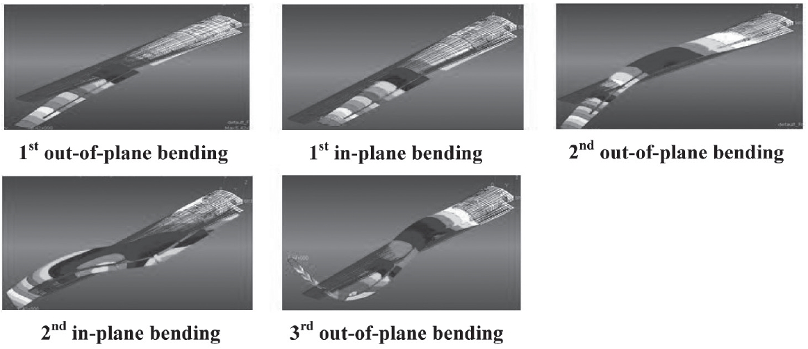
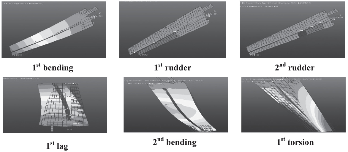
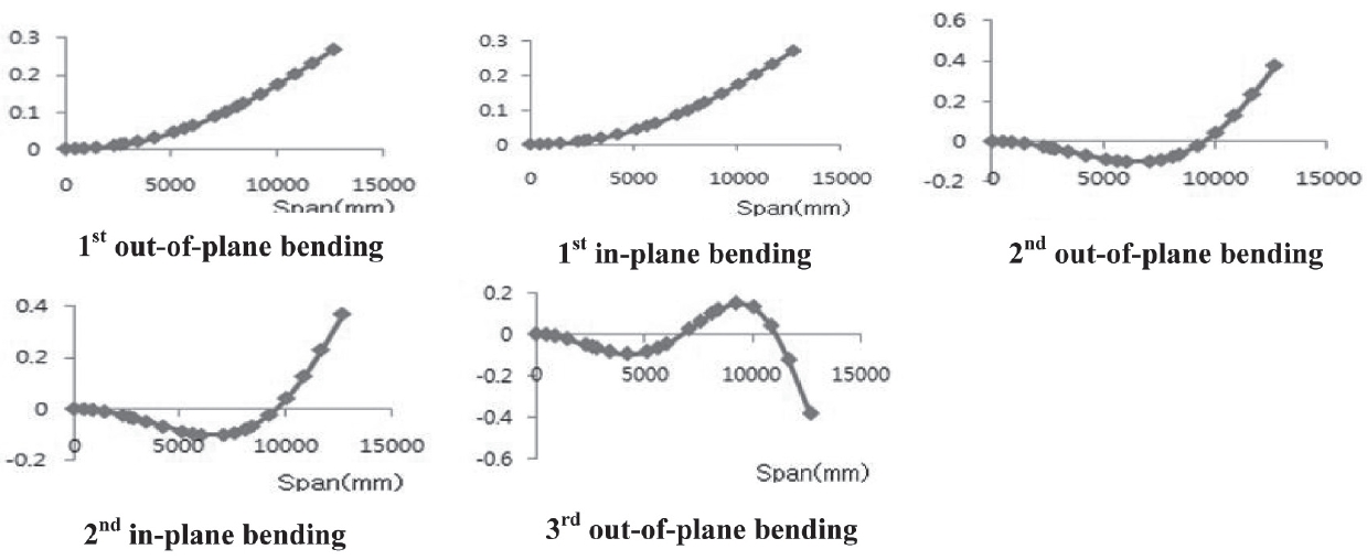
The vibration mode shapes are obtained through a one dimensional analysis of the linear Euler-Bernoulli beam. Moreover, ribs undergo a mass tuning since both their mass and stiffness properties could not be modeled in VABS. The mode shapes are presented below (See Figures 6 and 7). Later, these mode shapes are compared to the three-dimensional finite element data (See Figure 8). Through this comparison, the similarities and correspondence between the results in these two models becomes increasingly apparent.
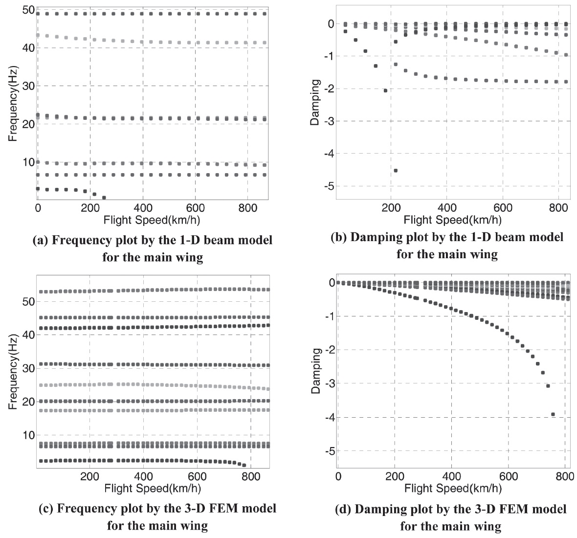
Upon obtaining the previous results, the aeroelastic analysis is performed using the first six modes of the Euler-Bernoulli beam. In order to facilitate the wing flutter analysis, a combination of the one-dimensional beam and ZAERO double lattice method is used. The results are obtained by the K-Method and G-Method, both of which use the generalized mass and stiffness matrices that were acquired using MATLAB for the one-dimensional beam, and then implemented into the .FRE files. The flutter result for the main wing is validated with the three-dimensional finite element model aeroelastic analysis which is based on the NASTRAN .F06 generated files as shown in Table 5. The flutter speed for the main wing was determined to be 670 km/h when combining the linear beam and ZAERO double lattice method. This was later validated with the results produced by the three-dimensional model’s flutter. The difference between the linear beam and the finite element model, in terms of the main wing flutter speed result, was found to be less than 8%. Besides, the dominant structural mode of the main wing flutter was found to be the first in-plane bending mode in the three-dimensional finite elements model. In terms of the frequencies, a difference of 56% was noticed for the main wing. By analyzing the plots corresponding to the main wing (See Figure 9), there was a mode whose imaginary root slightly went across the horizontal axis. It has been identified as being the 8th mode. This mode coincides with the aerodynamic lag mode added throughout ZAERO aeroelastic analysis, which has a zero frequency. Thus, it was anticipated that instability would occur at the corresponding flight speed.
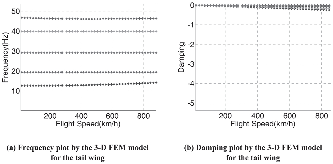
In Table 6, the results pertaining to the tail wing are presented. The flutter speed for the tail wing was determined
[Table 5.] Main Wing Flutter Prediction Results
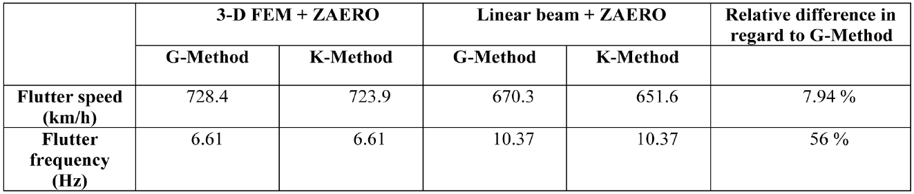
Main Wing Flutter Prediction Results
[Table 6.] Tail Wing Flutter Prediction Results
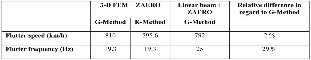
Tail Wing Flutter Prediction Results
to be 792 km/h when the linear beam and ZAERO double lattice method were combined. The difference between the linear beam and the finite element model, in terms of the tail wing flutter speed result, was found to be approximately 2%. The dominant structural mode of tail wing flutter was assimilated as the first out-of-plane bending mode in the three-dimensional finite element prediction. Also, the relative difference between the linear beam and the three-dimensional tail wing flutter speed result in terms of frequencies was lower than 30%. From the plots related to the tail wing (See Figure 10), one of the modes demonstrated abrupt behavior. It was identified as the 5th mode, which is, related to the first aerodynamic lag mode. Moreover, it corresponds to zero frequency and thus, it is possible that the tail wing undergoes a single degree of freedom flutter.
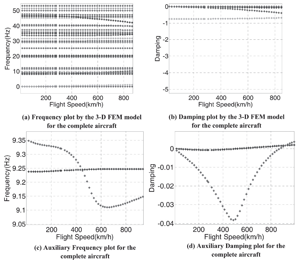
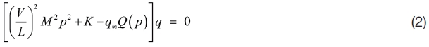
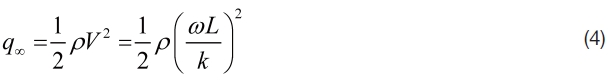
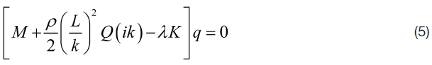
As for the entire aircraft, the flutter result from the threedimensional finite elements model is presented in Table 7. It was observed that the flutter speed in this case is lower than the one predicted in both Tables 5 and 6. Also, significant frequency coalescence was found in this case, unlike the previous main-wing only configuration (See Figure 11). This corresponds to the 14th structural mode. The frequency coalescence that occurred between the 13th andv 14th structural modes can be clearly noticed. The damping of the above mentioned modes goes over the horizontal axis, which corresponds to the flutter speed (See Figure 11 (c) - (d).). The coalescence that occurs throughout the entire aircraft configuration could be the product of the behaviors of the combined aircraft components’ interaction. One important aspect that cannot be determined without this combination is the anti-symmetric coupling that is caused by the pairing of both wings. Furthermore, results indicated that the instability in the main-wing only configuration corresponds to a single degree of freedom flutter, whereas significant frequency coalescence was found throughout the entire aircraft.
In summary, the flutter determined by the present linear beam approach shows similar and correlating flutter speed and frequency results with those determined by the NASTRAN model. However, the accuracy of the frequency versus flight speed, as well as the damping versus speed plots, appeared to remain dubious. It is particularly difficult in this instance to determine the precise reasons for the discrepancies and account for these inaccuracies. As such, the one-dimensional beam that has been used is considered as a crucial step before proceeding further in this analysis. Likewise, aerodynamic predictions were not validated independently. Subsequently, any aerodynamic predictions will need to be extracted and validated before further flutter analysis is conducted. For the aforementioned reasons, the need for an advanced model that would provide an expansion upon the present, and comparatively simple beam model, arises. For this reason, a separate aerodynamic dissection should be provided along with the structural
[Table 7.] Complete Aircraft Flutter Prediction Results
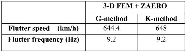
Complete Aircraft Flutter Prediction Results
analysis. Hence, this would enable enhanced accuracy and a more sophisticated analysis of the high aspect ratio wing.
4. Improved Approach to Capture the Geometrical Nonlinearity
One of the chief goals of this paper remains to provide an analysis of the interaction between the full six rigid-body degrees of freedom and aeroelastic modes. This very issue is believed to be a core component in understanding and enhancing the safety of unmanned aircrafts. Several notable incidents in these types of aircraft, such as the HELIOS aircraft crash, only serve to illustrate the gravity and urgency of this issue [13]. After exploring the development of the linear beam, as well as its structural and aeroelastic analysis, all while using the three-dimensional NASTRAN model as a reference; it is clear that the best way to understand this important facet of unmanned air vehicles is to use a nonlinear beam formulation along with the finite-state unsteady aerodynamics. This approach would afford a much more accurate and all-encompassing analysis of the high aspect ratio wings. As it now stands, this method is commonly used for rotorcrafts. However, the first implementation of this method, described in the work developed by Peters and He [14], dealt solely with fixed wings. Above all, using a combination of the nonlinear intrinsic beam and the finitestate unsteady aerodynamics, either for a fixed or rotary wing, would provide an accurate and thorough method for the analysis. On the other hand, another approach could also provide a thorough method to analyze the overall structure of these aircrafts. This method is based on the structural model for a highly flexible wing itself, which has also been largely used for rotorcrafts (especially for the hover case), in terms of the frequency domain. This method is an implementation of the nonlinear beam formulation without any simplifying ordering scheme. Of particular importance within this approach is the combination of finite-state dynamic inflow, unsteady aerodynamics, and the nonlinear intrinsic formulation. Another advantage of this method is that there is no degree of freedom reduction required to determine the nonlinearities, which is an indisputable advantage to this method. Therefore, this analysis could be both conducted in terms of either the frequency or time domain using any of these methods.
In conclusion, the theory presented is only applicable to a rotating blade, either cantilevered or simply supported in its present understanding. Consequently, this approach, one that is based on this structural model, will need to be modified in order to enable the analysis of a fixed wing with an incoming free stream, which will represent a different air flow pattern when compared to rotary wings. Moreover, the finite-state unsteady aerodynamics model, in its current form, also possesses its own inherent limitations, since it is based on an ideal fluid equation and neglects viscosity and compressibility. Therefore, it would be more accurate to consider a possible extension and reinforcement of this approach by gradually including and accounting for these effects. In brief, the use of the non-linear model would provide a much more accurate and precise result. In addition, an important feature and future objective of the current paper will be to perform the analysis and simulation of the flight dynamic response considering the six rigid-body degrees of freedom. By adopting this approach, the flutter analysis would be more accurate and allow for other important factors such as the trim impact as well as the deflection, to be accounted for. Over the last decade, few researches have attempted to develop the following analysis despite its increased accuracy and accountability. Without a doubt, the analysis of the response for MALE aircraft, including those that account for the six degrees, will only help to provide a clearer and more accurate study of MALE aircraft as a whole.
In this study, an aeroelastic analysis of an aircraft with high aspect ratio wings, developed for medium altitude and long endurance capabilities, was performed. In order to accurately and thoroughly analyze this aircraft and these inherent qualities, various structural models were implemented and analyzed. First, the cross-sectional analysis was conducted by using VABS. This was complimented by the high aspect ratio wing model, which was modeled as a one-dimensional beam. Additionally, the structural analysis for the main and tail wing were performed and the natural frequencies and the mode shapes were validated and compared with the three-dimensional NASTRAN model. The results obtained through this comparison demonstrated a strong and accurate correlation between the two models, in terms of both the natural frequency and mode shapes. These figures correlated with striking accuracy; for example, the natural frequencies of the one-dimensional beam demonstrated a maximum difference of 10% from those obtained through the three-dimensional model. In addition to this, flutter results of the main wing were obtained through combining the linear beam and the unsteady aerodynamics model in ZAERO. The flutter result for the main wing was validated with three-dimensional finite element-based aeroelastic analysis. After analyzing the one-dimensional beam, the results obtained were close to those predicted by the NASTRAN model. For the main wing, there was only a difference of 7.94% in terms of the flutter speed, and only a 2% difference was observed in the tail wing. What’s more, a new approach was suggested to provide a more accurate, succinct, and thorough representation of and comparison between the two models. This model, a non-linear beam model, would account for several important factors that remain largely unaccounted for in these two models, which include the trim effect, the steady state, the deflection, and the ability to overcome limitations produced by linearity.