Embedded systems continue to be the dominant market for all computer systems. Over the past few years, a number of new embedded domains have sprung up, including mobile devices and sensor networks. These new areas of applications have power consumption as the top design requirement, due to the use of batteries as the only supply of power. The limitation of a portable power source’s capacity still restricts devices, in terms of portability and durability. During active computation, the system performance varies widely and quickly, as a function of the workload. The higher the performance, the larger the power impact will be on the system.
Most of the sensor networks are built on low-end 8-bit and 16-bit microcontrollers. These low-end microcontrollers provide sufficient computation performance, but a boost in power efficiency can contribute to the widespread adoption of this technology. If current existing commercial products do not have advanced power management as a standard option, then it would be beneficial to seek out an external solution that can be added on, with minimal modification to the hardware.
Power management is not completely lacking in embedded system design. All microcontrollers are designed with low power as a design consideration, and the very large scale integration (VLSI) level has been highly optimized. What is currently lacking in microcontroller design is the ability to manage power at the high abstraction level. Embedded systems have traditionally focused on sleep modes, and have no active power management unit; some additional external schemes are needed in the design to enable dynamic on-the-fly power management.
Many power reduction schemes have been developed, and have been implemented as highly integrated systemon- a-chip (SoC) devices [1]. The research in this paper is to create a power management system that can be added on to existing microcontrollers that have no built-in power management support.
The target applications of microcontrollers differ from applications of general-purpose computers, in terms of computation. Microcontroller computation is concerned with retaining the throughput of the system. There is no need for increasing computation speed, because it yields no change in terms of throughput, which is in contrast to general purpose computing - the goal of which is to finish a computation as quickly as possible, to gain the most performance. As maintaining throughput is only required, the architecture can be redesigned with strategies that affect the logic speed or the internal cycles, but still yield the same functionalities. This paper will focus on maintaining the throughput of a microcontroller, by focusing on the chip frequency. By adjusting the chip frequency, power can be controlled. This approach is referred to as dynamic frequency controlling (DFC).
Dynamic frequency scaling (DFS) is one power reduction scheme that is commonly used in many central processing units (CPU) microprocessors found in products by AMD and Intel. By reducing the clock frequency to the minimal level of computation, it can reduce the frequency factor, linearly affecting the power consumption. DFS is built into the CPU, and is adjusted based on the workload or power supply currently connected to the CPU. In this paper we will discuss a similar concept, called DFC. DFC consists of an external circuit that is connected to a microcontroller. The external circuit will adjust the clock frequency, based on throughput information from physical interfaces/sensor connected to the microcontroller. The DFC will have a monitoring system that maintains the throughput, based on the interfaced sensor.
To fully understand the benefits of DFC, we must also understand the role of power at the software level. The goal of DFC is to change the energy required for each instruction at different clock frequencies. There is no benefit in power savings, unless an instruction consumes energy differently at different clock rates. The power consumption of the software will come down to a number of different components, including: the clock frequency, operands, memory register, and mixture of instructions used. One way to get an estimate of the power consumption is to look at the power consumed in an instruction-toinstruction operation. This paper examines the power consumption of every assembly instruction on the peripheral interface controller (PIC) microcontroller device PIC16F877A. Understanding the power at the instruction level allows us to estimate the power saving using DFC.
The work in this paper shows that DFC is one way to reduce power consumption, and that it can be added to off-the-shelf microcontrollers, with minor overhead. The DFC technique was added to the 8-bit PIC microcontroller in this paper to demonstrate the proof of concept of adding external power management. Results using real equipment show that a finite impulse response (FIR) filter example can save up to 10% with the addition of DFC.
The remainder of the paper is organized as follows: Section II discusses the previous research that has been conducted in the area of power management; Section III gives background information on energy measuring; Section IV discusses how the power was measured on the PIC microcontroller for each individual instruction and how the power measurements can be used to determine the power consumption of an algorithm; Section V lays out how DFC can be added to a commercial microcontroller; Section VI shows some verification testing; and Section VII concludes the paper, with a summary of the work that has been conducted.
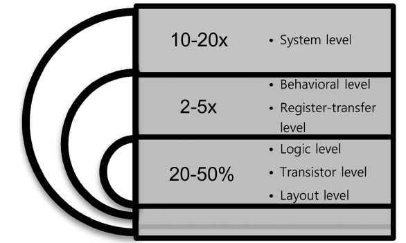
There are a number of options available for power consumption reduction in a microcontroller system. Each approach is suitable for some architectures and design targets. Some of the techniques will come at the expense of increased implementation cost, and can be done only at the manufacturer level, i.e., optimization at the transistor level. The user also can apply many techniques at the system level that are modifiable. According to Fig. 1, the higher the abstraction level to which a methodology is applied, the greater the potential power savings [2].
Power consumption reduction can be accomplished in many ways, ranging from adaptive processing technology, reduced switching activity, active power reduction, to changes in a system design; each scheme is applied at different levels. In embedded system applications, manufactured chips such as PIC microcontrollers are tailored and fixed. Modification at the gates-level is effectively impossible, and so is not considered.
One technique that is easy to implement in a design to save power is clock gating. Clock gating will allow for a
control signal to set when the clock is allowed to enter the system. When the clock gate is off, the system will not clock changes, resulting in no dynamic power dissipation. Clock gating is very useful at the VLSI level, and can be used to turn off part of the microcontroller. It could also be used to control the overall clock controlling the entire microcontroller. However, we do not consider the use of clock gating in this paper. The reason clock gating is not considered, is that by using clock gating we would remove the ability for the microcontroller to respond to interrupts. Microcontrollers are mostly used for realtime devices, and require the use of periodic timer interrupts. Microcontrollers must have a way to measure time, and clock gating will eliminate this feature if it is used.
Two techniques that can be added to a design, that do not require any changes to the gate-level implementation, are dynamic voltage scaling (DVS) and DFS [3].
DVS is a technique that is based on the fact that when the system is slower, the operating voltage can be reduced. According to the power equation P?, the energy consumed by the processor per clock cycle scales quadruples with the operating voltage, thus reducing the supply voltage, which can significantly reduce the overall power dissipation. This scheme needs some special hardware, such as a voltage regulator; and it is usually implemented along with the DFS technique.
The DFS technique conserves power by adjusting the clock frequency to the minimum level that is enough for computation. This scheme is widely used in computer architecture whereby the CPU automatically adjusts its speed by the workloads. This can reduce the switching activity.
DFS and DVS are techniques that must be built into the microcontroller. If a product does not have these features available, then the microcontroller has no power management system.
We performed a literature search of software power consumption in 8-bit low end embedded systems. Some work was done on power for embedded systems [4-6]. There are many papers on improving hardware performance, but not as many on software power optimization. Our search did find some early work on software power consumption using high-end 32-bit processors. While the 32-bit processors used are different from the 8-bit processor used in this paper, the previous work does lend some insight.
The first major study was made by Tiwari et al. [7]. This was a study on the effects software has on power consumption. Tiwari et al. [7] hypothesized that “by measuring the current drawn by the processor as it repeatedly executes certain instructions or short instruction sequences, it is possible to obtain most of the information that is needed to evaluate the power cost of a program.” During experimentation, almost every aspect of the instructions were examined, though of course some of them were found to have a negligible impact on the overall power consumption. The Tiwari et al. [7] model of power estimation ended up using the base cost of the instructions being used, as well as the inter-instruction effects present in the program, while neglecting the registers and immediate values being used. The work done by [7] is more in depth than the work we present in this paper. Tiwari et al. [7] needed to examine CPU techniques such as pipeline stalling and cache misses. With the power estimator developed by [7], a power reduction of up to 40% could be obtained, by reordering and replacing instructions.
An additional study made by Russell and Jacome [8] used a simpler model. They found that many items, including registers and condition codes, were insignificant, and could be ignored during experimentation. They also found that immediate values within instructions had a large effect, and needed to randomize the values to achieve an actual measurement. The final conclusion was that the average energy was roughly the same for each instruction. Their studies lead to the conclusion that there was no need to consider individual instructions when estimating power. By using run time, average power, and frequency, they were able to estimate the power used by a program.
The work by [7, 8] established the basis for all power consumption measurements and power estimators. The same techniques have been incorporated and expanded in SimplePower [9], Wattch [10], and XTREM Power [11]. While [9-11] have expanded the knowledge of power prediction, their techniques are not as applicable to the research we performed. Those newer techniques used a model of the physical architecture, or used performance counters that are not found in typical 8-bit embedded processors.
While there have been many more modern approaches to power estimation, such as the work done in [9-11], we focus on using similar techniques to those that were performed in [7, 8]. The main reason for our simple approach is due to the fact that the PIC microcontroller is only an 8-bit processor, and does not have any of the advanced CPU features. We also did not have the means to develop a cycle accurate model of the microcontroller.
The granularity of our power estimator will be at the instruction level. Determining the power consumed for each instruction will require a physical measurement to be made. The energy consumption is given by Equation 2,
E = P * T (1)
In Equation 1, P is defined as the average power over the time period T. The time period of our measurement will be the clock frequency of the microcontroller. The power is defined by Equation 2.
P = I2*R (2)
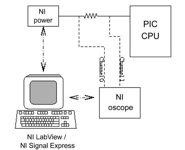
We are able to determine the power the microcontroller is consuming using Equation 2. To perform the measurement, we used a shunt resistor on the power supply of the microcontroller, shown in Fig. 2. We then used Equation 3 to find the energy used by the microcontroller, where n is the number of cycles to execute the instruction, and t is the clock period.
E = (I2*R)*(n*t) (3)
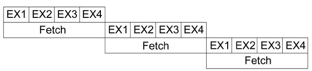
The PIC16F877A is a simple 8-bit processor that simplifies the measurements that need to be taken. The instructions are executed in a two-stage pipeline, as shown in Fig. 3. The two stages are broken into instruction fetch (IF), and instruction execute (EX). The EX stage requires 4 clock cycles to complete. When calculating the energy, we view every 4 clock cycles as a sample. The sample we take covers the 4 cycles for execution and the IF. We consider each sample as one complete instruction, since the fetch is independent of the instruction type, and the power consumption is captured, since it is pipelined.
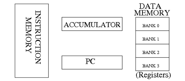
It is also important to know some basic information about the PIC architecture. The PIC is an 8-bit Harvard accumulator-based CPU. The data memory of the PIC serves as the registers for the CPU, and is broken down into 4 memory banks. The PIC is able to access a register or immediate values for each instruction. Fig. 4 gives a basic block diagram for the PIC architecture.
An important aspect of the power measuring experiment is the accuracy of the measurement being taken. We created a measuring procedure that is independent of the microcontroller’s clock speed. The voltage across the shunt resistor was connected to a National Instruments (NI, Austin, TX, USA) PXI-5112 100 MHz 8-bit oscilloscope. The power supply was set to 5.5 V, to compensate for the voltage drop that was dissipated across the shunt resistor.
The calculations for energy are computed using a mixture of NI’s LabView and SignalExpress. The current is found by subtracting the voltages across the shunt resistor, and dividing by the resistance of the shunt resistor. The NI software is used to determine the number of samples that are in a clock cycle, and finds an average current for the clock cycle. This data would allow us to monitor
[Fig. 2.] Power measuring technique. NI: National Instruments, PIC: peripheral interface controller.

the energy at the clock cycle time frame. We chose to work at the instruction level time frame, and find the average current for four clock cycles. To achieve better results, a large number of instructions were captured, and the average current was found. Once the current was found, the energy was determined, and all the data outputted to data file.
IV. ENERGY CONSUMPTION OF ASSEMBLY INSTRUCTIONS
The energy consumed is dependent upon the power supply of the microcontroller, along with the clock frequency. For this study, we kept the power supply on the microcontroller fixed to approximately 5 V, and allowed for a range of clock frequencies.
The PIC16F877A has a total of 35 instructions, and we looked at finding the energy for 32 of these instructions. The instructions that were not looked at were CALL, SLEEP, and RETIFE. The SLEEP function was difficult for us to measure, as we were unable to isolate the SLEEP function in our test plan. The RETIFE instruction was not examined, due to interrupts not being evaluated in this paper, but will be examined in the future. The CALL instruction was run, but we combined the results with Return from subroutine instruction, since it is common to run the two instructions in a pair.
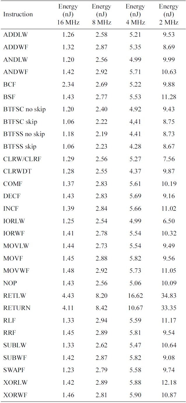
[Table 1.] Energy consumption for each PIC microcontroller instruction

Energy consumption for each PIC microcontroller instruction
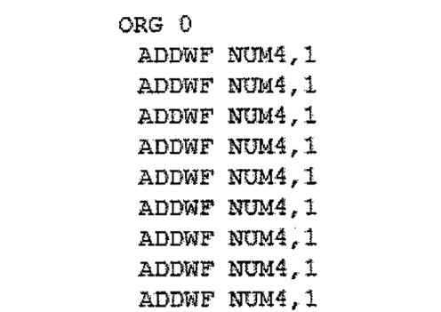
Each instruction was measured independently, and ran 1,000 times each. Fig. 5 shows an example of the code that was run to monitor the energy. The 1,000 times run ensured that different values were executed. Also, each instruction was run on 4 different operand values, and on 5 different registers. This data would tell us if all the instructions consumed the same amount of energy, or if the operands and register affect the energy consumption. The immediate values and operands were chosen at random. When using the register, each of the four banks was tested.
After all the testing was done on each of the 32 instructions, a number of interesting conclusions were developed. Each instruction did have a different energy consumption. The current draw for each instruction fell in the range of 6 mA to 8 mA, which is consistent with the datasheet that states a typical current draw of 7 mA. The operand did contribute to the change in current, but the results, which ranged from 0.5% to 3%, are insignificant. The memory bank that was used as a register also played a roll in the current values. The second memory bank consistently had a lower current compared to the other register banks, by up to 10%. The clock frequency had little change to the current draw from the power supply. The 16 MHz, 8 MHz, and 4 MHz values were fairly equal, and the 2 MHz clock had a 9% difference to the current. Table 1 shows the energy required for each instruction, for frequency between 16 MHz and 2 MHz.
When comparing the results of this paper with [7, 8], the PIC microcontroller showed similar behavior to [7]. The main difference between our work and the work in [7], is that the register values had a significant impact on the power consumption.
Using the results from Table 1, a practical example of running a one iteration of a FIR filter can give an estimate of the energy consumed in the operation. The FIR filter was created in a high-level language C, and then compiled to get the assembly instructions needed. Simple code for a 32-tap FIR filter is expressed as follows:
for(x=0;x<32;x ) output = coeff[x]*data[x];
The C code compiles into a total of 754 assembly instruc-
tions. The code has a main section to implement the for loop, and one subroutine to perform multiplication, since the PIC does not have a hardware multiplier. The filter coefficients and data are randomized, and analysis from the simulator shows that, using a 2 MHz clock, the total energy required would be 26,205 nJ. Understanding the energy requirement of each module in the software code is vital to predicting the battery life of a mobile device.
V. DYNAMIC FREQUENCY CONTROLLING
A microcontroller typically runs on a single frequency within the applicable range of the clock input. This frequency value, besides driving the circuit, is used in the software implementation to manage time-critical operations, such as communication routines, timing, or delays. Consequently, varying the clock input frequency affects the overall system operations.
To enable the DFC technique on a microcontroller without on-chip customization, system-level modification is considered. This yields a system applicable to any possible microcontroller. Instead of the typical scheme where a fixed oscillator feeds the microcontroller, the clock generator module takes control of the frequency input. The clock generator module is tied up to the system to enable the DFC feature, and is designed to be programmable by software. The programmable clock generator can be customized, either by loop-back control from the microcontroller or by external logic, and serves the operation of dynamic frequency control. The target microcontroller will be configured to get an external clock as the clock input, driven by the clock generator module. This scheme enables a microcontroller to run by the generated frequency, without any concerns of such controls. This design is made taking a generic approach that enables users to fully configure their own logic for clock control mechanisms.
The primary design of the system attempts to avoid hardware modification at all costs, to enable this system to be usable in a general application. This means only the software part is altered to deal with a system change, not the hardware.
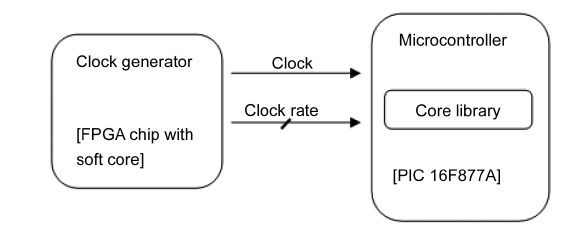
Fig. 6 shows the designed system scheme with the DFC feature. The clock generator module actively feeds the clock, along with the clock’s information, to the microcontroller. The clock generator is designed using a field-programmable gate array (FPGA) device incorporating a soft-core processor, which provides programmability and flexibility to the module. The clock generator is driven by software, and can be programmed using a highlevel language. This enables users to design their own mechanism on the clock generator module, i.e., a clock signal controlled by external logic, or by loopback control from the microcontroller itself. This scheme makes no modification to the microcontroller, beside the additional software library required for adjusting the internal logic towards the clock variations.
An FPGA with a soft core CPU is not required for the DFC. It was however used for its ability to manipulate the frequency by examining many outside factors, such as determining the throughput of the system. A complex programmable logic device (CPLD) can be used that will lower the power consumption of the clock generator, and still provide the functionality of having algorithms to determine the necessary clock frequency needed for the embedded system. It is also possible for the microcontroller to determine the clock speed needed, and set its own clock frequency, using a set of fix oscillators connected to a multiplexer.
A microcontroller is typically designed to work with one single frequency during run time. In many compilers, the feeding frequency is intensely used for generating time-related instructions. All of these operations are created at the compilation time, thus the feeding frequency information has to be provided at compile time. This restriction has limited the microcontroller to work in only one single frequency, because any subsequent modifications will collide with all the compiled instructions, and cause malfunctions to the system.
So as to enable on-the-fly frequency switching support, the software has to be redesigned to lean on the current feeding frequency, not the initial one. Since the frequency may change sometime in between operation, all time-relating components have to be ready to support the new frequency after the change occurs. This can be done through the support library that overrides the typical compiler function. All the time-related routines have to be replaced by on-the-fly adjustable routines that can adapt themselves to run on a new clock source.
When writing software for the microcontroller, most developers will write device drivers, or use device drivers that are part of a complier. Most compliers will include a C library that fully supports all operations for their PIC microcontroller development board. The C library is usable under the normal operating condition with one predefined clock frequency. During compile time, the clock frequency information is asked, in order to generate the corresponding assembly code and machine code. The compiler uses the clock frequency as a constant. Thus, any modifications to the provided library make no change. To enable scaling clock input under this environment, some parts of the library have to be replaced by the customized one. The replaced routines and their justifications are listed in Table 2.
>
B. Microcontroller Development Board Implementation Example
A number of input and output devices were used to
demonstrate the effectiveness in adding DFS to an offthe- shelf microcontroller. Only time-based input and output were used, because they are the only devices that can be affected by adding DFS. The devices used for this paper include: software timers (periodic interrupt based), liquid crystal display (LCD) device driver (for-loop based time delay), 7-segment light-emitting diode (LED; time multiplexing), and universal asynchronous receiver and transmitter (UART) serial communication (baud-rate generator).
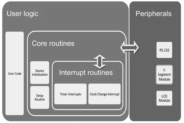
A high-level library was developed, to facilitate users to easily work with the DFS components, and use the DFS without concerns of clock changes affecting the software. The software libraries provided in this research are classified into three categories. A visual guide to the software libraries is shown in Fig. 7.
1. Core library ? Handles the present clock frequency, and manipulates all other components affected by
[Table 2.] Microcontroller library modifications to support dynamic frequency scaling
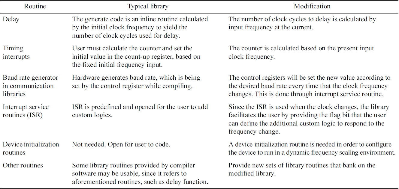
Microcontroller library modifications to support dynamic frequency scaling
frequency input, such as the interrupt service routine (ISR).
2. Communication library ? Controls I/O operations of communication module. In the project, the UART routines are implemented.
3. Peripheral library ? Manipulates the input/output of the time-relying components, such as 7-segment display or LCD display.
1) Communication Library
To support the communication module, UART routines are implemented, in addition to the library provided by the compiler. Since the clock variation affects the input frequency for the baud rate generator; it has to be reset in every dynamic clock change. This library has the capabilities to adjust the baud rate generator to meet the desired
baud rate with a given input clock. Typically, the baud rate generator setting can be obtained from the lookup table in the microcontroller unit (MCU)’s datasheet. In this circumstance, the baud rate setting is overridden by the calculation. This calculation is automatically made in the interrupt routine.
2) Peripheral Library
To make interfacing easier for programmers who want a layer of abstraction away from the DFS manipulation, a set of drivers was created that hides the introduction of the core and communication library. This library is only provided to make programming easier, and gives the programmer access to time varying hardware drivers.
A sample application was created to verify the concept of the external hardware addition of DFS, which is possible for commercial microcontrollers. The DFS clock generator module was designed on an FPGA. An FPGA is not required and lower power devices can be used. The clock generator was designed to operate between 0 Hz to 20 MHz. The DFS was able to generate 64 possible clock frequencies to the microcontroller. The clock generator can be configured in a high speed mode (20 MHz to 1.5 kHz) or low speed mode (5 kHz to 78 Hz) configuration. A listing of the clock frequencies available is shown in Table 3.
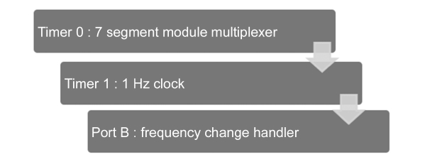
On the microcontroller, an example application was written that used the serial RS-232 protocol, software periodic timers, 7-segment LEDs, and LCD display. The microcontroller was connected to a PC that delivered I/O bound input. The microcontroller would perform calculations on the incoming data, and display the results on the LCD display. The software periodic timer was created to have a real-time clock. The periodic timer kept the current system time and updated the 7-segment LEDs. Fig. 8 shows how the software library was interfaced in this design.
In order to get an understanding of how energy could be saved by using the DFC, a test was conducted on a FIR digital filter. Signal filtering is a common task that many embedded systems required. The experiment was setup to measure a 32-tap FIR filter, with a sampling rate of kHz.
A top clock frequency for the PIC microcontroller was set to 16 MHz. The 16 MHz clock was chosen arbitrarily, and any clock frequency that can maintain a 1 kHz sampling rate could be used; this example is to show the savings one could achieve using the frequency available in our sample DFC. The energy required taking an analogto- digital converter (ADC) sample (running the FIR filter for one iteration) and wait for the next sample, using a static clock of 16 MHz, was approximately 8,880 nJ. By having the DFS system use 16 MHz to run the FIR filter code only, and then scale down the clock to 2 MHz to wait until the next sample needs to be processed, the same set of operations required approximately 8,330 nJ. A savings of approximately 6.2% was achieved, by scaling the clock by a factor of 8.
A larger reduction can be made if the DFC system uses 16 MHz to run the FIR filter, and then scales down the clock to 20 kHz. Using this new setup, the total energy required is 7,925 nJ. The total saving of 10.6% is achieved, instead of always running the clock at 16 MHz.
The DFS scheme for microcontroller was successfully developed to help microcontrollers operate in a DFS environment, without any hardware modifications. The PIC library software is implemented to facilitate users to develop applications, with the DFS hidden in the abstraction layer. Instead of a one fixed clock frequency, the clock generator module can provide any set of frequencies to supply the microcontroller. The libraries are available from the authors.
The results show the range of frequency that can be run in practice, ranging from 100 kHz to 20 MHz. Technically, the PIC16F877a is able to run on fixed frequency ranging from DC to 20 MHz, but less than 500 kHz frequency prevented other components that needed a high clock input, from working properly.
In the communication testing with a PC at a fixed baud rate, the microcontroller shows the ability to handle the data transfers with the various clock inputs. Some stumbles occurred when the source clock and the generating baud rate are too close, for example, when communicating at a high baud rate (e.g., 19,200 kbps) and the feeding clock is below 1 MHz. In the digital clock application, the precision of the clock is the same as the implementation on the PIC with the fixed clock source.
By using the power estimating software, a developer is able to determine the power being consumed at each frequency speed. The developer will be able to set the maximum frequency to determine the power consumption at
[Table 3.] Clock speeds available for the dynamic frequency scaling system
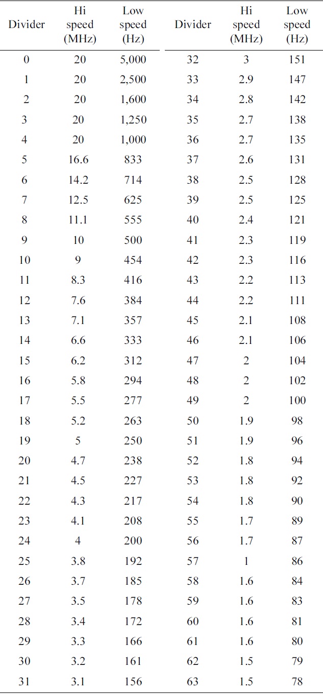
Clock speeds available for the dynamic frequency scaling system
peak performance. Energy savings will be gained as the DFS adjusts to maintain the throughput of the embedded system.
The work in this paper shows a low-cost and effective solution to improving the power consumption in commercial microcontrollers. While this work has shown a modest improvement of 10% in real applications, we believe additional improvements can be gained with software optimization. This work is just a starting point in creating a power management system for embedded microcontrollers. Future work is needed to understand the potential savings to other microcontrollers and understand which applications could benefit the most from the added power management system. The simple hardware and software library will allow for any developer to use our system with minimum development time overhead.