Visible light communication (VLC) is a kind of wireless optical communication technique using light-emitting diode (LED) light [1-4]. It is an area of growing interest with the worldwide growth of the LED illumination market. VLC is emerging as a candidate for future indoor wireless communications because in indoor applications VLC has several advantages over conventional radio frequency (RF) wireless communications: 1) it is harmless to humans because it does not use electromagnetic waves, 2) we can freely use visible light because there are no regulations for the use of visible light in indoor applications, 3) the current RF resources are depleted but the potential communication bandwidth of visible light is incomparably wider than RF, up to 400 THz, 4) visible light is easily blocked by walls, so we can easily maintain communication security between rooms, and 5) we can easily identify the state of VLC operation because we can see visible light.
However, the direct modulation bandwidth of LED devices is currently limited to less than 1 GHz. Thus the data rate of early VLC works has usually been less than 1 GHz and the transmission distance has also usually been less than 10 m [5-7]. If we find a way to increase the data rate and transmission length of VLC, VLC could be a strong candidate for future indoor wireless communications. Therefore, previous studies have proposed several techniques such as equalization [8] or complex modulation [9] for increasing VLC data rates. Recently, simulation research to investigate an optical multiple-input multipleoutput (MIMO) technique based on non-imaging and imaging approaches to achieve high data rates was performed [10].
In this paper, we report an experimental demonstration of 4 × 4 MIMO wireless VLC using a commercial chargecoupled device (CCD) image sensor receiver instead of a photodiode receiver. We believe that an image sensor is a promising commercial candidate for a VLC receiver in the near future. An image sensor is an optical receiver similar to a digital camera, which is composed of many pixels that can detect optical intensity [11]. It is currently installed in most mobile devices such as smart phones or laptop computers and can also be used for VLC. By using image sensor receivers, we can easily implement optical parallel transmission to increase the data rate.
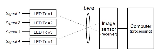
Fig. 1 shows the block diagram of the 4 × 4 MIMO wireless VLC using an image sensor receiver. Four binary signals are generated by a function generator and each binary signal modulates each LED. We controlled the voltage level of the binary signals to optimize the LED output optical power. The four LED lights are focused on different pixels of the image sensor through the focusing lens. The image sensor continuously detects the optical intensity on the pixels. The received optical data stream of each pixel is acquired and transferred to a control computer.
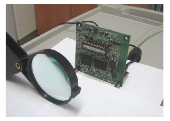
In the experiment, we used four Hamamatsu L10762 (Shizuoka, Japan) LEDs as the VLC transmitters. Only one LED is used for each transmitter. We used a Hamamatsu S11071-1004 image sensor and a related driver circuit as the receiver. The image sensor has 1,044 × 22 pixels and the active sensor area is 14.336 × 0.224 mm. A convex lens in front of the image sensor is used to focus the transmitter lights onto the image sensor. Fig. 2 shows the photograph of the implemented receiver part.
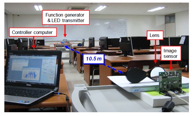
Fig. 3 shows the photograph of the 4 × 4 MIMO VLC experiment with a transmission distance of 10.5 m. By using the experimental setup shown in Fig. 3, we conducted the 4 × 4 MIMO wireless VLC experiment. The LED output optical power in the experiment was 0.024 lm, which is about 0.58 mW in 660 nm light. The spacing among the four LED transmitters was 20 cm. The data rate of the modulating binary signal was 200 bit/s per LED channel, which was not limited by LED transmitters, but by the processing speed of the image sensor receiver.
The image sensor used in the experiment has two receive modes: a line-detection mode and area-detection mode. The line-detection mode means that only one row of the image sensor actively detects the optical intensity. In other words, the image sensor operates like an image sensor of 1,044 × 1 pixels in line-detection mode. Furthermore, the area-detection mode means that all of the pixels actively detect the optical intensity. In the experiment, we used the line-detection mode because the processing speed of the line-detection mode is faster than that of the area-detection mode.
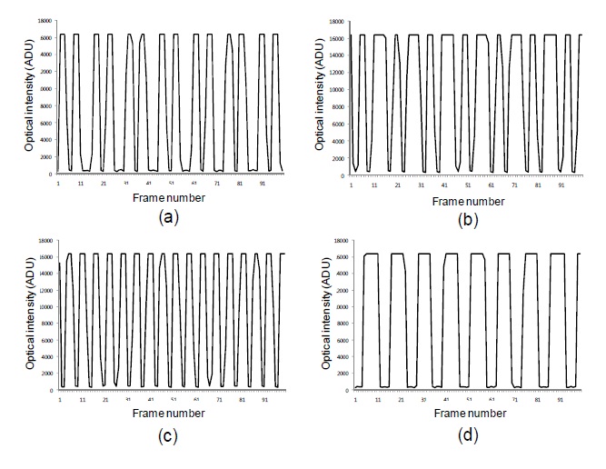
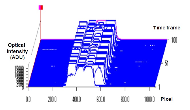
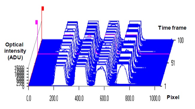
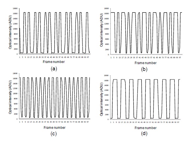
Fig. 4 shows the received optical intensity as a function of column pixel and time. Four different binary bit streams were detected on the four different pixel ranges by aligning the focusing lens. The reception ranges of the four signals are pixel 220?270, 380?430, 550?600, and 720?770, respectively. Fig. 5 shows the received optical intensity as a function of time at pixel 230 (channel #1), 390 (channel #2), 570 (channel #3), and 750 (channel #4). The binary stream of channel #1 is 10,100, channel #2 is 10,110, channel #3 is 1,010, and channel #4 is 1,100. The eye diagram of each signal is clear enough to receive a signal.
In the experiment, the transmission rate was constrained by the processing speed of the image sensor. However, the transmission rate can be increased by using more MIMO channels. The transmission distance is mainly constrained by the spacing of the transmitter images on the image sensor. Therefore, the transmission distance can be improved by using wider transmitter spacing or a better lens alignment system. We expect that a transmission distance of tens of meters can be possible using the same devices used in this experiment.
To investigate the limiting condition of the transmitter spacing, we conducted the same experiment with a transmitter spacing of 9 cm. Fig. 6 shows the received optical intensity as a function of the column pixel and time when the spacing among the four LED transmitters was 9 cm. It can be observed that the four channels overlapped slightly. However, the four channels can be received separately if we choose an appropriate pixel for each channel. Fig. 7 shows the received optical intensity as a function of time at pixel 355 (channel #1), 435 (channel #2), 505 (channel #3), and 605 (channel #4) when the spacing among the four LED transmitters is 9 cm. The binary stream of channel #1 is 10,100, channel #2 is 10,110, channel #3 is 1,010, and channel #4 is 1,100. We can recognize that each channel was clear enough to receive as it was when the spacing among the four LED transmitters was 20 cm.
We report an experimental demonstration of a 4 × 4 MIMO wireless VLC system using a commercial image sensor receiver. Due to the processing speed of the image sensor, the data rate was limited to 200 bit/s per LED channel, a total of 800 bit/s for the 4 × 4 MIMO. However, the data rate can be increased by using more MIMO channels. The transmission distance was over 10 m, enough for most indoor applications, and it seems that a longer transmission distance is possible using the same experimental devices.
Most modern mobile devices such as smart phones or laptop computers have a built-in digital camera, which is a kind of image sensor. Thus, VLC based on an image sensor can be used through these devices. The only drawback of an image sensor is its low processing speed. However, we expect that a high-speed image sensor for VLC will appear in the near future.