The Korean nationwide differential global positioning system (DGPS) consists of ocean-based DGPS for ocean service and land-based DGPS for land service. The oceanbased DGPS of 11 reference stations and the land-based DGPS of 6 reference stations are operating and providing differential GPS service nationwide [1]. The DGPS transmits an enhancement GPS signal that the receiver stations may use to correct their pseudo-ranges. The DGPS reference stations provide the service information using the minimum shift keying (MSK) modulation with a 200 bps data rate in the frequency range of 283.5?325 kHz [2,3].
The ocean-based DGPS covers the service area of 100 NM by the output power of 300 W; on the other hand, the land-based DGPS transmits the output power of 500 W, which covers the service area of 100 km. The DGPS reference stations with high output power can radiate spurious signals, which may act as interference sources affecting the other DGPS reference stations or the wireless ground stations that utilize the medium frequency (MF) band. Also, the power amplifier (PA) of the DGPS system is operated in the switching mode; therefore, spurious signals are generated from the PA and may be radiated from a DGPS reference station. It is necessary to analyze the interference effect on other DGPS reference stations and user terminals from the spurious signals.
In this paper, the radiation spectrum characteristics of the DGPS reference station are measured and analyzed from the perspective of spectrum purity and the interference effect from spurious signals of the DGPS reference station. The output spectrums of the ocean-based DGPS of 11 reference stations and the land-based DGPS of 6 reference stations are measured near the DGPS system.
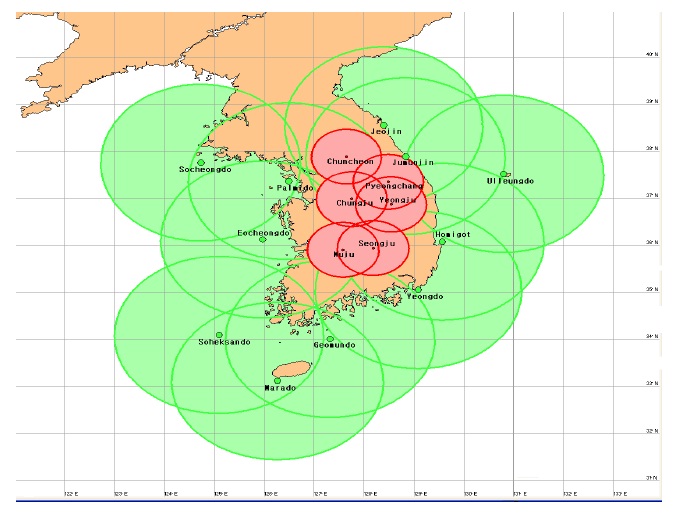
Fig. 1 shows the service areas of the Korean NDGPS that are provided from the ocean-based DGPS of 11 reference stations and land-based DGPS of 6 reference stations [1]. The ocean-based DGPS provides DGPS service for the ocean area, while the land-based DGPS covers the landbased service area that cannot be provided the service from the ocean-based DGPS. The NDGPS reference stations are operated with an output power of 500 W for the land-based DGPS and 300 W for the ocean-based DGPS. Therefore, the DGPS service areas overlap each other, which improve the service availability. On the other hand, the overlapped service area can cause interference with user terminals by spurious signals from another DGPS reference station.
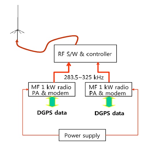
The spurious signals originate from the DGPS reference system, especially the power amplifier of the DGPS reference system. The DGPS reference system consists of an MSK modulator, power amplifier, and other units shown in Fig. 2.
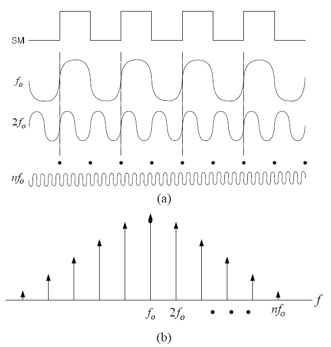
The MF power amplifier in the DGPS reference system is operated in the switching mode. In the switching operation mode, the harmonic signals besides a fundamental frequency signal are generated as shown in Fig. 3.
To reject harmonic signals, which can act as sources of interference, a band-pass filter is used in the output stage of the power amplifier. Furthermore, to eliminate the possibility of interference from another DGPS signal, the transmission frequencies of DGPS are allocated with a sufficient frequency offset. Table 1 shows transmission frequency allocation for the Korean DGPS. The DGPS transmission frequencies are allocated in the frequency range of 283.5 kHz to 325 kHz with a frequency offset of over 1 kHz [1]. However, the antenna of the DGPS reference station is usually the top-loaded antenna type [4,5]. The ground side of the MF antenna is a series of radials. Radials are crucial in the design of a top loaded antenna as the electrical properties of the antenna require the reaction between the top loaded portion and the ground system. The radiation pattern and input impedance of the DGPS has effects due to the ground plane [6]. The spurious signals of the DGPS may be affected by the antenna operating conditions and environment.
III. SPECTRUM MEASUREMENT OF DGPS REFERENCE STATION
To analyze the interference effect on other DGPS user terminals and other wireless ground stations due to the spurious signals, the radiation spectra of DGPS reference stations are measured and analyzed in the interference domain.
The radiation spectra are measured near the DGPS reference system and over two kilometers’ distance from the DGPS reference station.
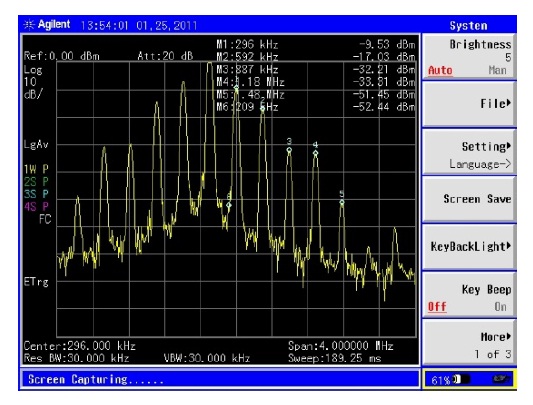
The radiation spectra near the DGPS reference system are typically measured as shown in Fig. 3b. The radiation spectrum near the DGPS reference system is shown in Fig. 4. The fundamental frequency, which is the desired radiation signal, and the harmonic signals are measured around the DGPS reference system. Far away from the DGPS reference station, however, the fundamental signal is only measured at a distance. Fig. 5 shows the fundamental spectrum measured from a distance.
[Table 1.] Transmission frequency of the Korean NDGPS reference station
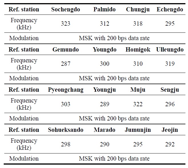
Transmission frequency of the Korean NDGPS reference station
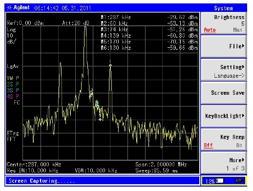
In the case of the ocean-based DGPS, the fundamental signal is measured far away from the DGPS reference station. The typical radiation spectrum for the ocean-based DGPS reference system is shown in Fig. 6.
The measured spectra are categorized into four patterns, a fundamental spectrum, a fundamental spectrum with 2nd harmonic signals, a fundamental spectrum with a spurious signal around the second harmonic frequency range, and a fundamental spectrum with spurious signals near the fundamental signal. Those spectra are shown in Figs. 6?9.
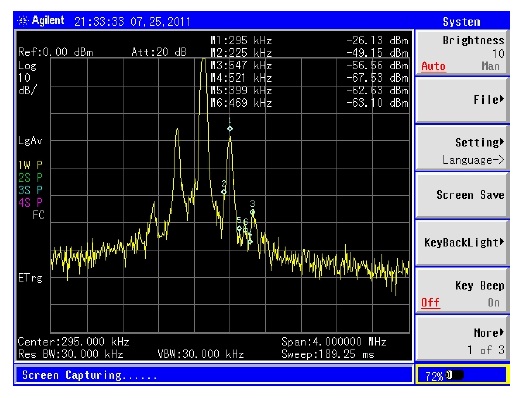
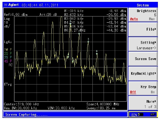
In the operation of the DGPS reference system, a large number of harmonic signals appear in the output signal domain (Fig. 4). The fundamental spectrum is only measured at a faraway distance (Figs. 5 and 6). In this case, the spurious signals besides the fundamental signal, which are evanescent signals do not propagate to a faraway distance. However, the second harmonic signal of DGPS was measured in the Ulleungdo DGPS reference station as shown in Fig. 7.
Fig. 10 shows the measured spectrum near the Ulleungdo DGPS reference system. Like the other DGPS reference systems, a number of harmonic signals including a fundamental signal appear around the DGPS reference system. As the propagation distance is increased, it is known from Fig. 10, and Fig. 7 that the second harmonic signal power decays from -20.56 to -60.41 dBm with about 39.9 dB propagation loss, while the fundamental signal power experiences a propagation loss of about 5.6 dB (from -8.93 to -14.48 dBm). Although the second harmonic signal subsists within close range of the DGPS reference station, it is knownharmonic signals do not radiate to a faraway distance via the DGPS antenna.
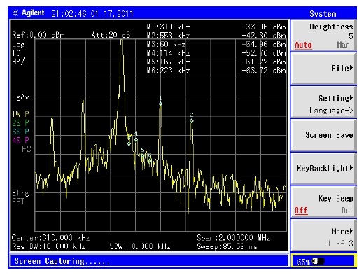
The fundamental spectrum with a spurious signal around the second harmonic frequency range was measured as in Fig. 8. In Fig. 8, the spurious signal is a signal with a frequency of 558 kHz, which bears no relation to the DGPS signal (310 kHz) of the Homigok DGPS reference system. The signal may be a transmission signal of another wireless ground station using an MF frequency range. Spurious signals similar to Fig. 8 were measured for an ocean-based DGPS reference station (Echeongdo station with spurious signal of 547 kHz; Fig. 11). This is because the other MF wireless ground stations for ocean service are operating near a DGPS reference station.
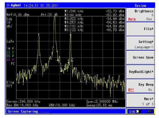
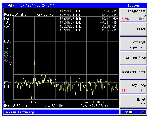
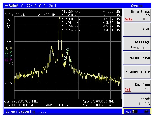
Fig. 9 shows a fundamental spectrum with spurious signals near the fundamental signal. A large number of spurious signals near the fundamental signal were measured in the case of the Marado DGPS reference station. To analyze the effect of in-band transmission noise, the spurious signals close to the fundamental signal were evaluated in the frequency domain as shown in Fig. 12. It is known from Fig.12 that the in-band noise within a channel bandwidth of 500 Hz does not affect the DGPS reception performance. The spurious signals close to the fundamental signal are generated by other wireless ground stations and adjacent DGPS reference stations, which does not affect DGPS user terminals. This is because the DGPS receiver rejects the outof- band signals with a 40 dB rejection ratio.
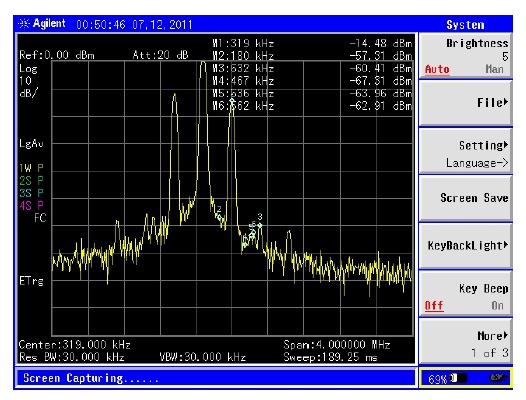
[Fig. 13.] Measured DGPS signals with adjacent DGPS channel (Jeojin, 292 kHz and Jumunjin, 295 kHz).
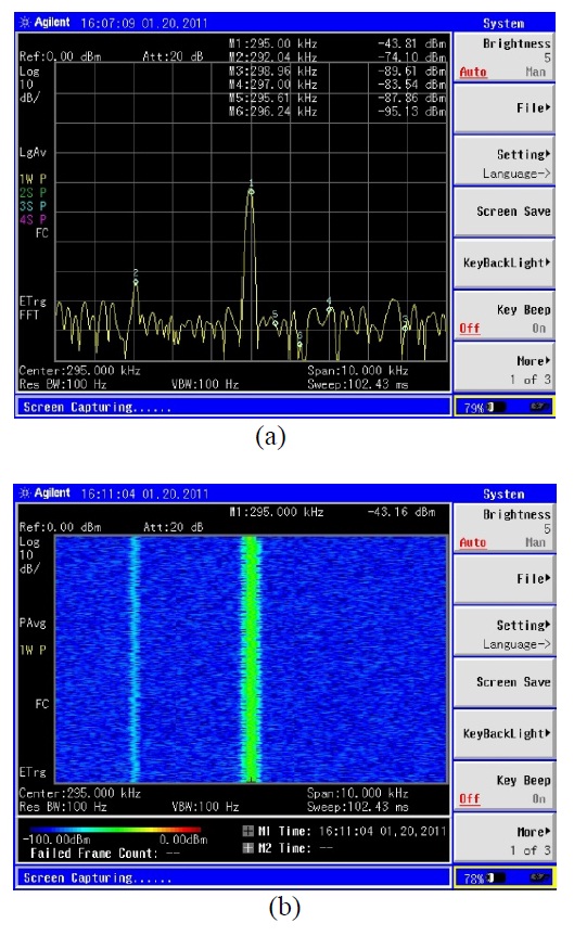
There are adjacent DGPS signals around the radiation spectrum of the Marado reference station as shown in Fig. 12. The radiation signals of Echeongdo DGPS reference station (295 kHz) and Sohueksando DGPS reference station (298 kHz) were measured as adjacent DGPS channels.
The MF DGPS signal that propagates as a surface wave has effects due to the conductivity of the propagation media. In a propagation plane with a good conductivity, the DGPS signal propagates to a faraway distance. The ocean-based DGPS for ocean service, which have better conductivity than that of the ground plane, can service a wider area than can the land-based DGPS. Therefore, a number of DGPS signals can be propagated in a service area. Fig. 13 shows a DGPS spectrum with a propagation signal of an adjacent DGPS reference station, where the channel frequencies of Jeojin (adjacent channel) and Jumunjin reference station are 293 kHz and 295 kHz, respectively.
The radiation spectra of Korean DGPS reference stations using the MF band are measured and analyzed from the perspective of the interference effects due to spurious signals. The spurious signals disappear at a faraway distance, while a number of the spurious signals are measured near the DGPS reference station. The desired fundamental signal of the DGPS reference station is only radiated via the MF transmitting antenna.
The harmonic signals of the DGPS signal originate from the power amplifier of the DGPS system. The signals does not radiate via the MF DGPS antenna. Though the spurious signals close to the fundamental signal are generated by other wireless ground stations and adjacent DGPS reference stations, it is known that the spurious signals do not affect the DGPS user terminals.