In the past decades, fiber Bragg grating (FBG) sensors have been studied extensively for sensing several types of physical parameters such as temperature, strain, bending, and pressure [1-6] with optical methods. FBG sensors have the advantages of immunity to electromagnetic interference, compact structure, simple fabrication, and easy construction of long range monitoring system by using wavelength-multiplexing schemes with cascaded FBGs. However, for temperature sensing itself, the temperature sensitivities of bare FBG sensors are low due to the low thermal expansion coefficient of silica with temperature variation [1]. To increase the temperature sensitivity of the FBG sensor, several types of modified FBG sensors have been proposed. The earlier researchers studied deposition methods using metal or metal complex compounds with high thermal expansion coefficients to enhance the temperature sensitivity [7-10]. However, the metal deposition process on the silica fiber requires complex fabrication steps, for which it is difficult to control the deposition layer precisely due to the radial shape of optical fibers. The residual stress, produced during the metal deposition process, on the interface between the deposited metal and the glass also makes it difficult to design the resonant peaks of the metal-deposited FBG sensors precisely [10]. For the case of using polymers for enhancing the tem-perature sensitivity of FBG sensors, the fabrication process can be comparatively simple because the polymer cladding layer can be made simply by a general coating process, but their temperature sensitivities are not good due to the low thermal expansion coefficient [11, 12]. In addition, the thermal dimensional stability of a polymer should be con-sidered to be used for the temperature-sensitivity-enhancing materials because the thermally expanded volume of most polymers cannot be restored completely to an initial volume after cooling.
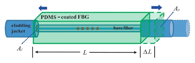
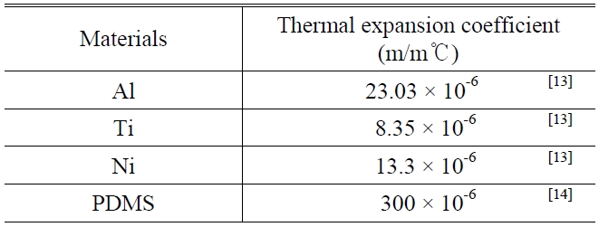
In this study, we propose a poly-dimethylsiloxane (PDMS)- coated FBG temperature sensor, where the PDMS is used for enhancing temperature sensitivity as shown in Fig. 1. The thermal expansion coefficient of the PDMS is much higher than those of metal materials previously used for enhancing temperature sensitivity in metal-coated FBG sensors as shown in Table 1[13, 14]. Thus, the temperature sen-sitivity can be effectively enhanced by the tensile force induced by the thermally expanded PDMS. Because the PDMS is a chemically stable elastomeric polymer, the thermally shifted resonant peak in our structure moves back to an initial wavelength without dimensional stability problems. In addition, we can make the PDMS jacket on the FBG very easily due to its good adhesion on the silica surface by using a simple molding process [15]. However, the enhancement of the temperature sensitivity in the PDMS-coated FBG sensor is not much higher than the large thermal expansion coefficient of the PDMS itself. It is because the Young’s modulus of the silica is much higher than that of the elastomeric PDMS. Here, we give an analytic model to describe the enhanced Bragg wavelength shift of the proposed structure in response to the increased temperature, and we demonstrate the temperature sensitivity according to cross-section areas of the PDMS jackets.

The thermal expansion coefficients of materials used for enhancing temperature sensitivity of optical FBG sensors.
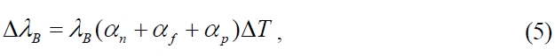
The FBG structure can measure the temperature variation by monitoring the shift (Δ

where
where
where Δ
Here,
Considering the thermally induced refractive index variation in the silica fiber, the Bragg wavelength shift of the PDMS-coated FBG sensor according to temperature change can be written as follows.
where
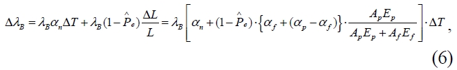
where

is the effective photoelastic coefficient (~0.212) of the fiber [17].
3.1. Fabrication and Measurement of the PDMS-coated FBG Temperature Sensor
For the PDMS-coated FBG sensor, the FBG (SMF-28) with total longitudinal grating length of 10 mm was utilized in our experiments, which presented the central wavelength of 1549.6 nm, the 3 dB bandwidths of about 0.1 nm and 0.2 nm, and the peak reflectivity of about 90%. Before coating the PDMS onto the FBG, the cladding surface of the FBG was pretreated with the oxygen plasma at 30 W for 30 seconds to enhance the interfacial adhesion between the PDMS and the optical bare fiber [18]. The PDMS jacket was fabricated with a molding process by using the PDMS with a 10:1 mixing ratio of precursor of elastic material (Sylgard 184-A) and hardener (Sylgard 184-B), where the length of the PDMS jacket was
on the device dimension condition of the PDMS jacket and to compare the experimental results with the derived analytic model. For the PDMS-coated FBG sensor with the PDMS jacket with
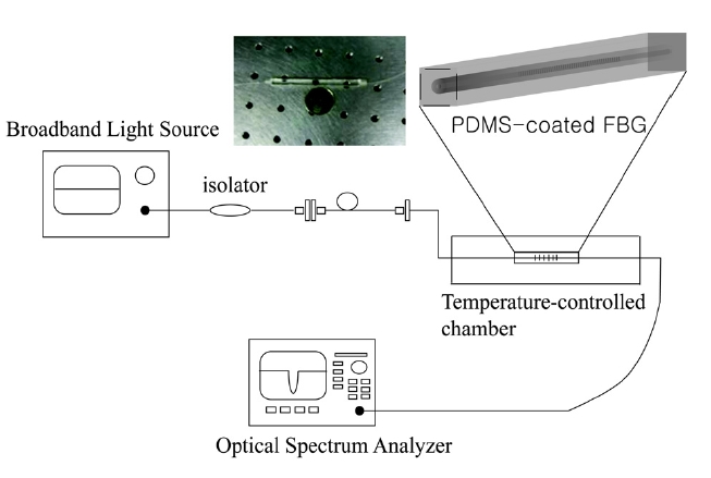
As shown in Fig. 2, a broadband light source (Opto-Link Corporation Ltd. OLS15CLGB-15FA) was connected to the proposed FBG sensor with an optical isolator. The trans-mission spectra of the PDMS-coated FBG sensor were monitored using an optical spectrum analyzer (OSA, Ando AQ-6315A) with a resolution bandwidth of 0.05 nm. During the experiments, temperature was precisely controlled from 30℃ to 120℃ by using a temperature-controlled pyrostat.
3.2. Enhancement of Temperature Sensitivity by the PDMS Jacket
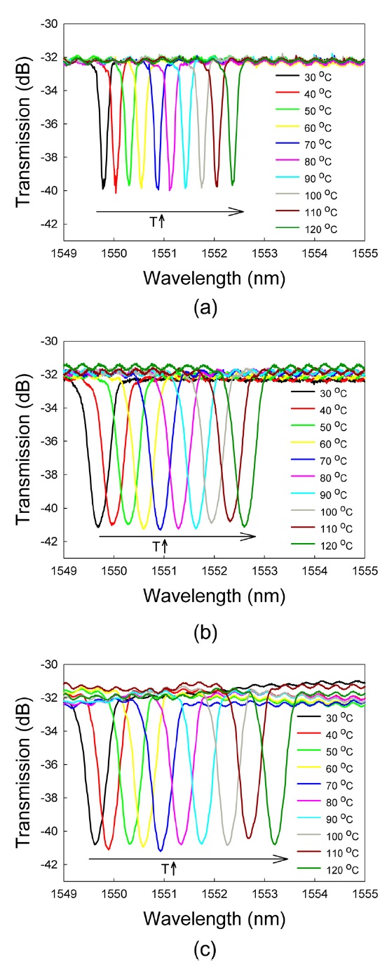
Figure 3 shows the transmission spectra of the PDMS-coated FBG sensors at various temperatures, where the cross-section areas of the PDMS-jackets are
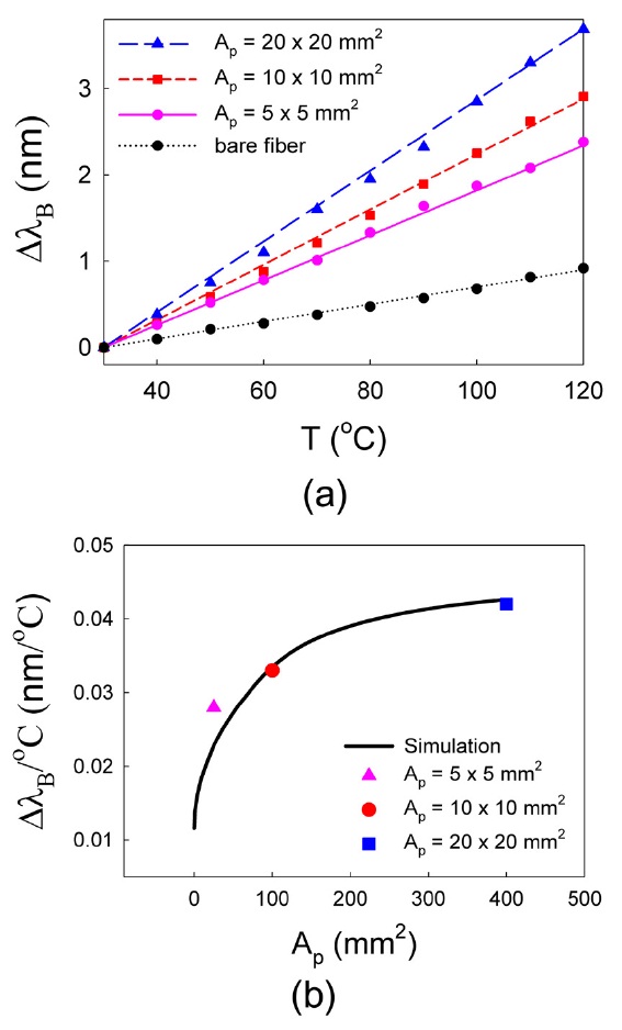
Figure 4(a) shows ΔλB|s of the PDMS-coated FBG sensors for various cross-section areas of the PDMS jacket according to temperature variation, where the dots and the lines
denote the experimental results and the simulation results from Eq. (6). For comparison,
and 0.042 nm/℃ (for
The material parameters used for theoretic values, as depicted in Fig. 4, from Eq. (6) are that the diameter of the bare fiber is 125 ㎛ , and the Young’s moduli of the PDMS and the bare fiber are
Figure 4(b) shows the temperature sensitivity of the PDMS-coated FBG sensor for various values of
We proposed a highly temperature-sensitive FBG structure,where the bare FBG was coated with the elastomeric PDMS jacket layer. The analytic model was also derived, which matched well with the experi-mental results. The experimental results as well as the theoretical model showed that the amount of the tensile force onto the PDMS-coated FBG, induced by temperature variation, was highly dependent on the cross-section area of the PDMS jacket, which means that we can use our structure for enhancing temperature sensitivity effectively or for tailoring temperature-dependent spectral shape change for several other sensing appli-cations with modified PDMS shapes. The proposed PDMS-coated FBG sensor is expected to be widely used for various applications due to its high temperature sensitivity, easy fabri-cation,high durability and stability without interfacial residual stress between the PDMS and the fiber.