The controlled use of fire is an impetus to human civilization, but the runaway forest fire can cause great damage and the loss of life and property. The airborne infrared (IR) detection technique has been applied in the area of wild land fire detection for nearly half a century. It is widely used to detect, monitor, and orientate fire suppression and mop-up operations. Tradition infrared systems are mounted in two styles --nadir or gimbaled. The sensor is pointed directly below the plane belly and provides a relatively narrow field of view with nadir mounts. These systems are capable of imaging a large incident promptly, and help the fire managers to get a snapshot of the conditions. With gimbaled mounts, widely known as forward-looking IR (FLIR) balls, the IR equipment mounted on a stabilized turret pointing nearly any direction is not masked by the plane body, and is very practical for fire-line mapping and mop-up operations. They scan the object from different angles, thus the FLIR can discover fire which may elude nadir-mounted systems. However few of FLIR balls are mounted on fixed winged aircraft as most civilian planes have a low body and the turret is protruding beneath the plane chassis. Stones rising from airfield runway are likely to crush the FLIR window as the plane taxies. Besides, the projecting turret increases air resistance and reduces cruising speed.[1-4]
According to the above analysis it is necessary to investigate an improved airborne IR detection system which is inside the plane body to avoid injury, mounts with a tilted porthole conformal to the prow for decreasing air drag and has an appropriate scanning mechanism able to provide a large field of view.
II. ABERRATION ANALYSIS AND CORRECTION
2.1. Tilted Glass Porthole Aberration Analysis
The nose of a firefighting cruising plane model could be simplified as an ellipsoid. A typical value of the ellipsoid length divided by the height can be taken as 2.
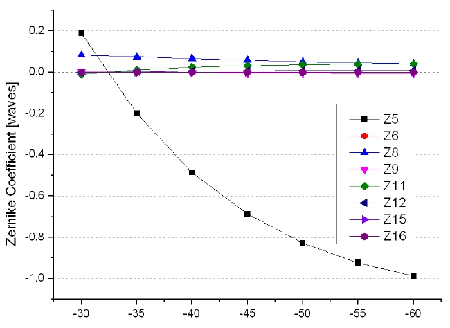
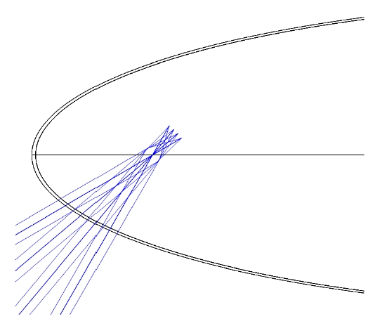
Fig. 1 shows the layout of the ellipsoidal plane nose with a perfect lens at four different scanning positions from -30° to -60° in 10° increments. Fig. 2 shows large amplitude selected Zernike aberrations across the wide FOR (Field of regard -the area covered for the detector of the system when pointing to all possible mechanically positions5). As shown in the chart (wavelength = 4 ㎛) the dominant aberrations caused by an ellipsoidal dome are 3rd order
astigmatism (Z5). So the fundamental challenge is to find an appropriate scheme to correct this large aberration.
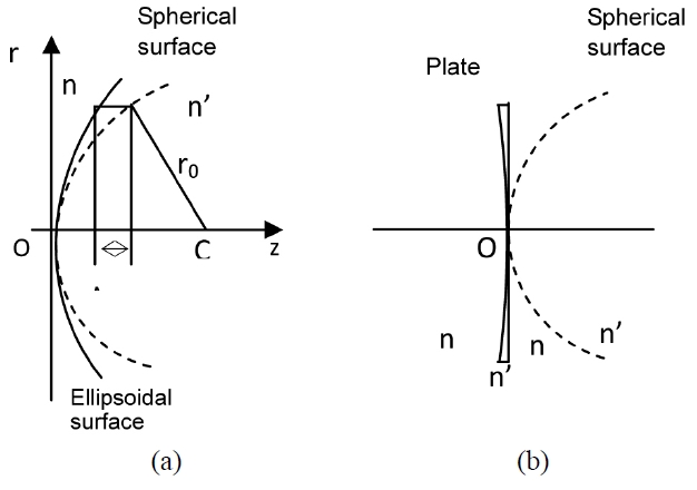
2.2. Theory of Primary Aberration for the Ellipsoidal Surface
Aberration characteristics of the ellipsoidal surface are similar to those of a spherical surface except for the distri-bution among surfaces. To calculate the primary aberration distribution of an ordinary aspheric surface, one ellipsoidal surface can be considered as the overlap of one spherical surface and another zero center thickness plate as shown in Fig. 3, where the z axis is the optic axis, r axis is the meridian plane coordinate axis, O is the origin of coordinates, r0 is the datum surface radius, c is the center of curvature, Δz is thinness increment of the zero center thickness plate, n and n’ are material refractive indices before and after the surface respectively.
Relative to a spherical surface which has the same axial curvature radius r0, the 3rd order astigmatism aberration coefficients increment of the ellipsoidal surface can be
described as
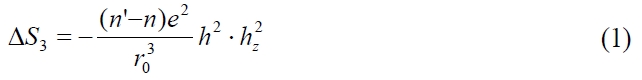
where h is the intersection height of the paraxial ray on the aspheric plate, hz is the intersection height of the chief ray on the aspheric plate, and e is eccentricity.[6-8]
The additional aberrations induced by the ellipsoid surface (0< e2< 1) could be described by the above expression (1). Because the e2 increment is in direct proportion to -e2, an oblate element (e2< 0) can provide balance of additive 3rd order astigmatism induced by the ellipsoidal porthole(0< e2< 1). The opposite signed additive aberrations can be cancelled out for different conic surfaces. We suppose that one conic plate corrector could correct the additional aberrations induced by an ellipsoid optical window with appropriate aperture position.
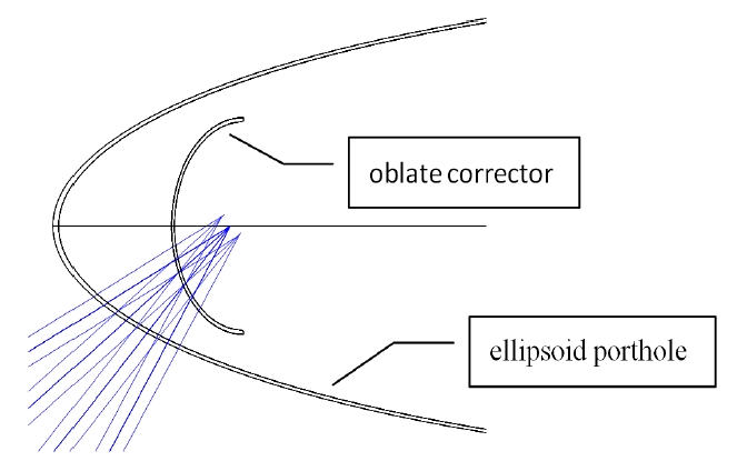
2.3. Oblate Corrector for Ellipsoid Nose Porthole
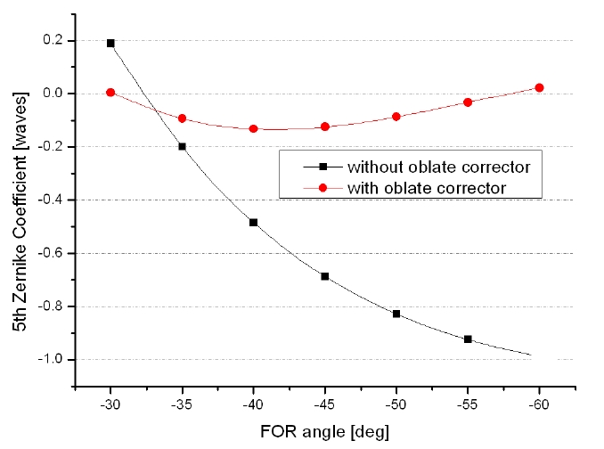
The ellipsoid MgF2 porthole glass is to be compensated in this design. We take advantage of the powerful features of commercially-available optical design software to optimize the oblate correction element. Fig. 4 shows the system layout followed by a perfect F/4 lens at 4200 nm wavelength across the -30° to -60° FOR. Zernike aberrations are analyzed with and without the oblate corrector respecti-vely as shown in Fig. 5 (wavelength = 4 ㎛), which indicates that the corrector has compensated the 3rd order stigmatism to a great extent.
III. SCANNING OPTICAL SYSTEM DESIGN
3.1. System Scheme and Specifications
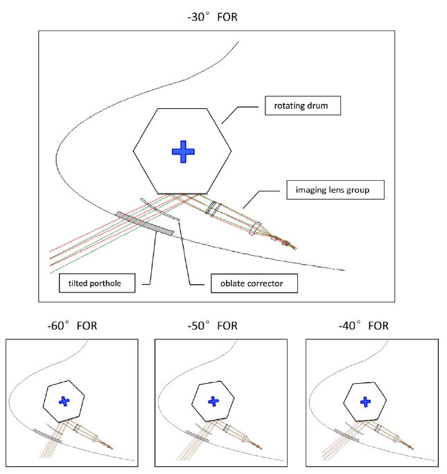
Fig. 6 shows the design of a complete scanning IR optical system with tilted MgF2 porthole, oblate corrector, rotating drum and imaging lens. The porthole glass and
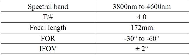
[TABLE 1.] Relevant specifications for the entire IR optical system

Relevant specifications for the entire IR optical system
oblate corrector are similar to those analyzed in section 2.3. Table 1 lists the design specifications. IFOV means the instantaneous field of view.
3.2. Simulations and Optimizations Methodology
The complete system layout shown in Figure 6 is the result of a stepwise design process. A reflective rotating drum is adopted for scanning the target fire. The drum center is located on the optical axes of the MgF2 porthole and the oblate corrector. The subsequent imaging system is a conventional secondary imaging structure. It has 100%
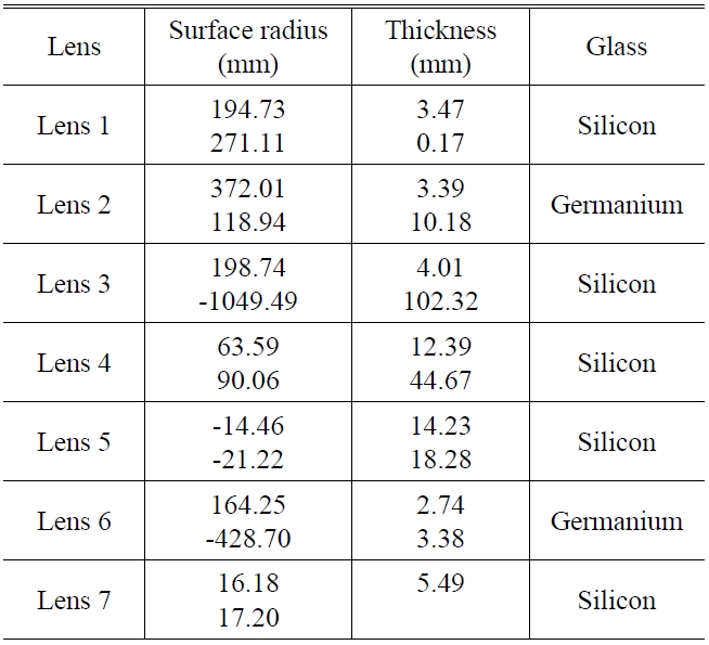
[TABLE 2.] Imaging lens surface parameters

Imaging lens surface parameters
cold shield efficiency and can reduce the radial size of the system.[9] Ultimate optimization of the complete structure for all four different FOR position results in the final design. Table 2 lists detailed imaging lens surface parameters.
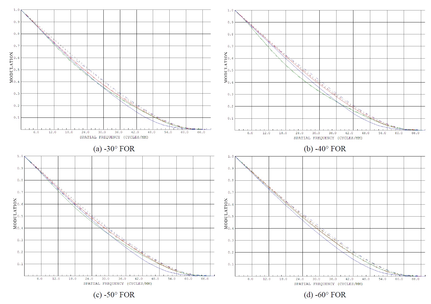
The system’s ultimate modulation transfer function (MTF) of the IR scanning optical system is approximately at the diffraction limit as shown in Fig. 7.
[TABLE 3.] Some tolerance items of the corrector
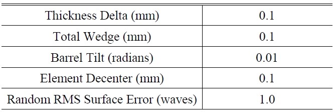
Some tolerance items of the corrector
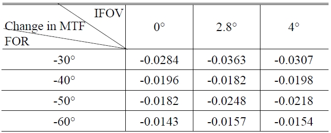
[TABLE 4.] Probable change in MTF for 20 cycles/mm

Probable change in MTF for 20 cycles/mm
Table 3 lists some of tolerance items of the corrector and Table 4 lists the probable change in MTF for 20 cycles/mm at 97.7% cumulative probability.
We have shown the design of an IR scanning optical system for airborne wild land fire detection equipment with a rotating drum. The reflective drum is an effective and practical way to scan large FOR and also the oblate corrector is appropriate in compensating aberrations arising in a tilted porthole. This optical system provides an easy-fabrication and low-cost scheme for land wildfire alarms.