Holography records the phase modulation of light reflected or transmitted from a projected object onto a photosensitive plate in the form of interference. A reference and an object beam are required, and an interference pattern is generated as a result of the combination of the two beams. Previously, interference patterns were recorded on film plates. However, charge-coupled device (CCD) and complementary metal-oxide-semiconductor (CMOS) technology are now widely used to capture images, and the holograms are then reconstructed on computers. Yaroslavskii and other researchers first proposed hologram reconstruction on the basis of numerical values in the 1970s [1-5]. Ounral and Scott used numerical reconstruction to measure the size of a particle after improving the reconstruction algorithm [6]. This method of digital recording and reconstruction of a numerical hologram is known as digital holography [7-10]. Digital holography has many advantages; for example, it does not require any chemical processing because the reconstructed image can be observed easily on a computer monitor, and numerical data can be obtained for three-dimensional (3D) objects [11,12].
However, the phase information becomes ambiguous and causes phase wrapping when the phase change exceeds 2π. Dual-wavelength holography has been suggested as a way of overcoming this ambiguity [13-16]. Dual-wavelength holography is a technique that extends profile measurements deeper than single-wave holography. Digital holography usually uses a laser, a high-coherence source. The coherent beams are very sensitive to any defect in the optical paths and are affected by coherence noise, which severely reduces the optical quality of the resulting reconstructed images. To eliminate the coherence noise problem, partial coherence sources are used in digital holography. The partial coherence sources are obtained from filtered light-emitting diode (LED) sources or from a laser source with deliberately decreased coherence. These partial coherence sources improved the reconstructed image and reduced coherence noise in digital holography [17,18].
In this study, we measured a ball-grid array (BGA) using a dual-wavelength digital holography technique. We chose to use partial coherence sources because the surface of the BGA was rough and its height was larger than the source wavelengths. We also used a reference conjugated hologram (RCH) for a phase-compensated phase map in dual-wavelength digital holography.
1. Hologram Recording and Reconstruction
In the hologram recording process, a plane reference wave (

where

where
In classical optical holography, the object wave can be reconstructed by illuminating the processed hologram with a plane wave similar to that used in the recording process. Looking through the hologram, one observes a virtual image. If a screen is placed at a distance
where λ is the wavelength, and
and
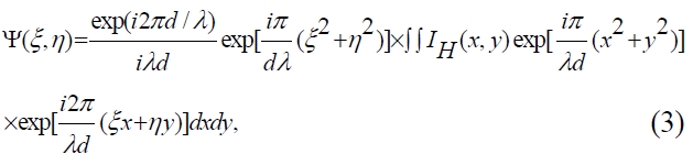
From Eq. (3), the Fresnel-Kirchhoff integral can be considered the Fourier transformation of the function

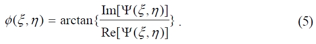
The phase-contrast image is obtained by calculating the argument
The real 3D information is acquired by phase unwrapping with the phase-contrast image. Usually the lasers are used in DHM and are sensitive to any defect in the optical paths, and are affected by coherent noise. These coherent noises degrade the reconstructed image quality. To eliminate the coherent noise, partial coherent sources are suggested in DHM. The partial coherent sources are obtained by laser and RGG [18,22].
2. Dual-wavelength Holography and Phase Aberration Compensation
Consider two single-wavelength phase maps,
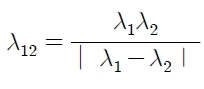
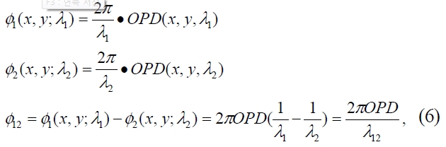
The value of λ12 can be increased by selecting values of λ2 and λ2. that are closer to each other. The phase map for λ12 is obtained by subtracting one single-wavelength phase map from the other. This map is called a “coarse map” [14]. To make a corrected
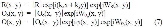
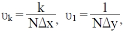
Where kx, ky define the wave propagation direction and WR, Woo are the phase difference between perfect reference wave and object wave. The reconstructed wave front is given by Eq. (8).
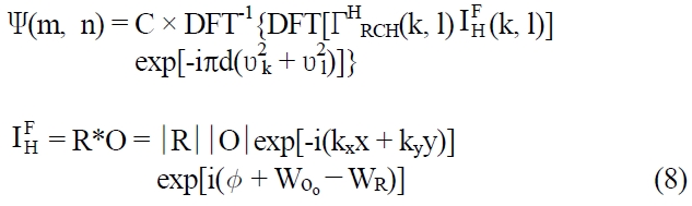
Here
and

is the filtered hologram, and WOo?WR describing the aberration. We could compensate the aberration, WO

as the conjugate phase of Eq. (8),

The multiplication of

with filtered hologram results in a suppression of the aberration terms [21],

Eq. (10) shows that the total aberration can be compensated [19-21].
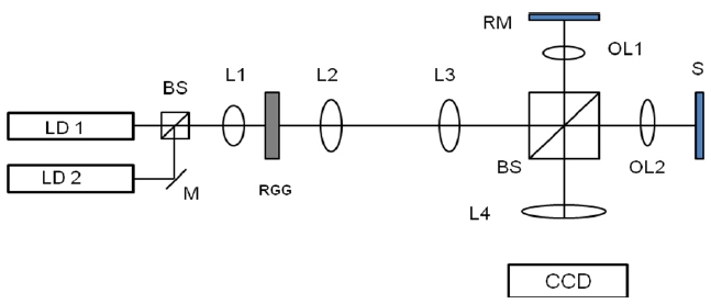
Figure 1 shows a schematic of a dual-wavelength transmission holographic microscope. The basic experimental setup is similar to that of a Michelson-type interferometer. A 668-nm laser diode and 677-nm laser diode were used as the light sources. These coherent beams were focused on the scattering surface of a rotating ground glass (RGG). The RGG was rotated in its plane by a motor. The light
transmitted by the RGG was scattered by its rough surface to create a speckle field that varied with the ground glass rotation. The scattered surface of the RGG was placed in the front focal plane of the lens, L2. Lenses L2 and L3 were used for beam expanding. We used a CCD camera (Sony IPX1M48L) to record the holograms. The pixel size and the number of pixels were 7.4 μm × 7.4 μm and 1024 ×1024, respectively. The CCD was placed in the focal plane of lens 4 (L4). We used a BGA with a height of 15 μm as our sample.
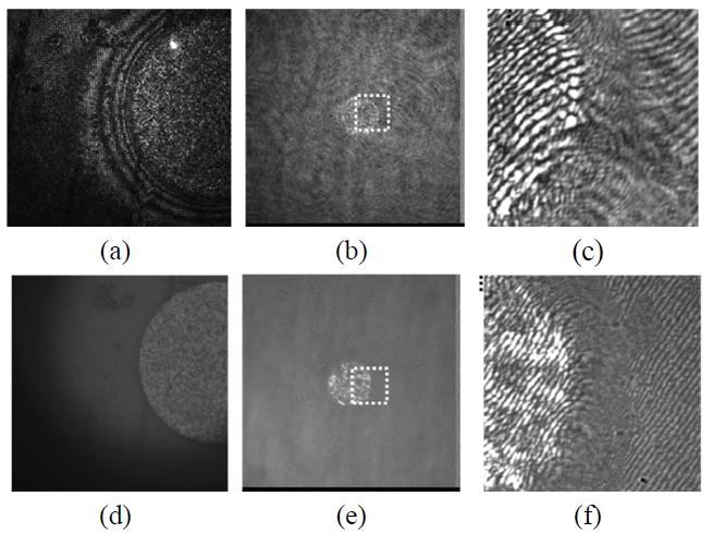
Figure 2 shows the partial coherence effect for the BGA. Figures 2 (a) and (b) present a coherent source image and hologram, (d) and (e) are partial coherence source image and hologram, respectively. Figure 2(c) and (f) are expanded image of dotted square part in Fig. 2(b) and (e). Figures 2 (a) (b) (c) and (d) (e) (f) were obtained without and with the RGG in Fig. 1, respectively. We have used the 50X microscope object lens for the image in Fig. 2 (a) and (d), and Fig. 2(b), (e) are from 20X microscope object lens. The surface of the BGA was rough, which caused coherent noise. We can show that the noise degraded the image and the hologram in Figure 2(a), (c) and the partial coherence source-improved image and hologram in Figure 2(b), (d). The partial-coherence-source method using the RGG resulted in a spatial low-pass filtering in digital holography [18].
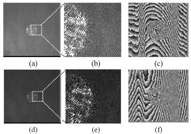
Figure 3 shows the dual-wavelength holography experimental results. Figure 3(a) and (d) are the holograms created by laser diode 1 (668 nm) and laser diode 2 (677 nm), respectively.
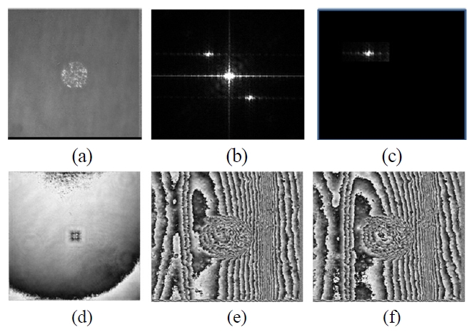
Figure 3(b) and (e) show the expanded hologram image of Fig. 3 (a) and (d). Figure 3(c) and (f) show the reconstructed phase map of each hologram. These are not aberration compensated. Each phase map has aberrations, tilt, and centering. We could not extract the right sample phase information without compensating for the tilt aberration. We took the RCH to compensate for the tilt and centering aberration, and detail process are in Fig. 4. Figure 4 (a) is
the hologram, which is same in Fig. 3(a) and Fig. 4(b) is the FFT image of hologram (a). We can get the filtered hologram

as like Fig. 4(c) and Fig. 4(d) is the hologram without sample

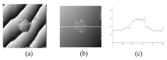
Using Fig. 4(c) and (d) we can get the reconstructed phase map (Fig. 4(e)), which is phase aberration compensated. Figure 4 (f) is another phase aberration compensated phase map using Fig. 3(d). We subtracted phase map Fig. 4(e) from phase map Fig. 4(f) to construct a phase map of the equilibrium wavelength (λ12 = 50248 nm). The result appears in Figure 5(a). Figure 5(b) shows the gray level of the 3-dimensional in Fig. 5(a) and Fig. 5(c) is the height profile from the phase measured along the white line.
We measured the BGA height as 15±1.2 μm. The error is relatively large because the error was amplified in the subtraction process between phase maps. This amplification is well known. From these results, we could eliminate the 2π ambiguity using dual-wavelength holography and reduce the coherent noise by partial coherence sources. Also, we could use the correct phase information by compensating for the aberration using a RCH.
Dual-wavelength holography is useful for obtaining profile measurements without including a 2π ambiguity. Using partial coherence sources reduced coherent noise. The BGA had a rough surface, which caused coherent noise. Its step height was larger than the visible wavelength, which resulted in a 2π ambiguity in the digital holography. We used a dualwavelength holography method with partial coherence sources to measure the BGA’s height and shape. From experimental results, we showed that the dual-wavelength holography method using partial coherence sources is useful in measurement samples that exhibit coherent noise and whose heights are larger than the single wavelength used in holography.