Variable-focus lenses, with focal lengths that can be adjusted by manipulating the lens shape or a with a graded refractive index, have boundless possibilities for applications in a great variety of microscale optical devices such as cell phone cameras, capsule endoscopes, optical pickup heads, and microscopes [1-5]. Diverse driving forces for focal-length control have been introduced by numerous research groups. For instance, an electrowetting-based lens [6-8], dielectrically actuated lens [9, 10], fluidic-pressure-based lens [11-15], liquid-crystal lens [16-18], and polymer-gel lens [19] have been reported. Both electrowetting-based lenses and dielectrically actuated lenses use external voltage to control the shape of a refractive liquid, and they exhibit fast responses without moving mechanical parts for focal-length modulation. However, performance degradation is unavoidable with these lenses, which consist of two immiscible liquids in a lens cell. This degradation results from liquid residues on solid surfaces, condensation at low temperature, and shape hysteresis of liquid interfaces by captured charges [20-22]. Liquid crystal lenses have the complexity of electrically controlled refraction as well as the need for additional optical parts such as polarizers that avoid focusing behaviors due to optically anisotropic liquid-crystal molecules, which greatly reduce the transmitted optical power. Polymer-gel lenses are inadequate for microscale optical systems, because they require an external compressive stress for activation. The driving force of a fluidic-pressure-based tunable lens is the deformation of an elastomeric diaphragm filled with liquid. In general, refraction is controlled by either liquid injection from an external supplier or liquid flow induced with an integrated micropump. Because an external liquid supplier is impractical due to its large volume, integration of the actuator is essential for a miniaturized adaptive lens system [14, 15]. Three miniaturized fluidic-pressure-driven lenses with integrated actuators have been previously reported [11-13]. However, the hydrogel-based fluidic-pressure lens is not convenient to use, because it is activated by chemical manipulation[11]. Moreover, an electromagnetic-actuator-based fluidic-pressure lens needs additional permanent magnets and provides limited focal-length tunability [12].
In this study, we demonstrate a variable-focus liquid lens with an integrated actuator driven by thermopneumatically controlled fluidic pressure that affords great focal-length tunability. Specifically, the laterally integrated actuator to a lens cell converts the expansion of air heated in a sealed chamber into fluidic pressure that results in focal-length modulation without thermal crosstalk. To achieve the necessary focal-length tuning range, the structure of the proposed lens is designed according to Joule’s law and Pascal’s law simultaneously. The elasticity and thickness of the diaphragms at the air chamber and lens cavity, the area ratio of those diaphragms, and the optical properties of the liquid all play key roles in lens performance and so are considered with great care during the design phase. The proposed variable-focus liquid lens provides excellent focal-length tunability from infinity to 4 mm with a lens aperture diameter of 2 mm. Moreover, this utilization of a thermally separated thermopneumatic actuator to drive a variable-focus liquid lens has performance superior to the earlier reported therm-opneumatic liquid lens in power consumption, response time, and thermal crosstalk [13].
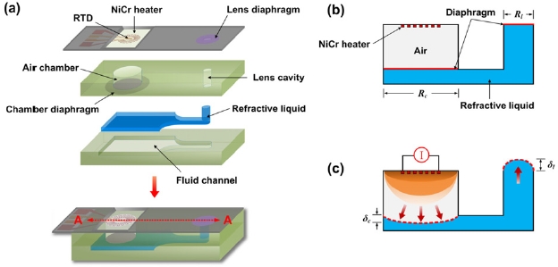
Figure 1 shows the proposed variable-focus liquid lens and its operating principle. As shown in Fig. 1(a), the lens is composed of three parts: a thermopneumatic actuator, a fluid channel, and a liquid-filled lens cavity. The thermo-pneumatic actuator consists of a metallic heater in a sealed air chamber with a thin elastomeric diaphragm, as shown in Fig. 1(b). When power is supplied to the heater, the elasto-meric diaphragm is deflected by air pressure that is thus delivered through the fluid channel to the liquid-filled lens cavity. The corresponding diaphragm that seals the lens cavity is then deformed by the liquid pressure delivered by the incompressible fluid channel. This deformation of the lens diaphragm results in a change of focal length that is determined by the tunable deflection of the lens diaphragm,
as shown in Fig. 1(c). In order to avoid thermal crosstalk shown in the vertically integrated microlens by Zhang et al. [13], this thermopneumatic actuator and lens cell are laterally integrated using polydimethylsiloxane (PDMS) components with low thermal conductivity (0.18 W/m?K) as shown in Fig. 1(a). The vertically integrated microlens showed temperature gradients of 0.2-4℃ in the lens optical aperture. The metallic heater and the lens cavity are fabricated on a silicon wafer using micro-electro-mechanical systems (MEMS) technology, while the other parts are formed with PDMS. The fluid channel is completely filled with refractive liquid. In this study, a silicone oil (refractive index,
Joule heating of the metal induces a volume change in the air chamber and in turn a pressure load on the lens, as shown in Fig. 1(c). The dependence of the pressure load,
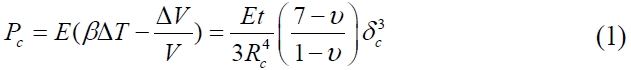
where
where
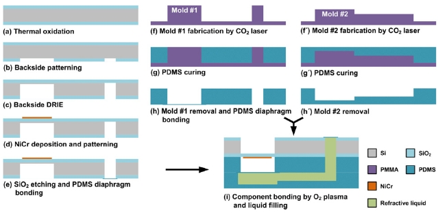
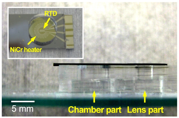
To demonstrate the optical performance of the variable-focus liquid lens, we fabricated the lens as illustrated schematically in Fig. 1(a). The silicon wafer, including the metallic heater and part of the lens cavity, was fabricated using thermal evaporation and deep reactive ion etching(DRIE) to form the heater and etch the cavity, respectively. The metallic heater was designed with a cogwheel shape for enhancing the Joule heating efficiency. NiCr (80 wt% Ni and 20 wt% Cr) was employed for the heater because of its excellent resistance to thermal corrosion. The bulk silicon on the backside of the heater was etched away using DRIE to minimize the heat loss resulting in high heating speed at the air chamber. The PDMS parts (Sylgard 184, Dow Corning, 10:1 ratio of base to curing agent) contained the chamber cavity, fluid channel, and lens cavity. These PDMS components were replicated using a poly-methyl methacrylate (PMMA) mold that was precisely machined using a carbon dioxide (CO2) laser. Two 13-㎛-thick elastic diaphragms for the air chamber and the lens cavity were prepared by spin coating PDMS onto a flexible polyethylene terephthalate (PET) film and subsequently were joined with the patterned PDMS structure by following a lamination process. In advance of the PDMS coating, a fluoropolymer layer (AF1600, Dupont) was formed onto the PET film to form a hydrophobic surface, which enabled the PDMS diaphragm to peel easily from the PET transfer film during the lamination process. The laminated diaphragm was firmly bonded using an oxygen (O2) plasma treatment for 30 s. Once the silicon and PDMS parts were completed, these were aligned and then combined through successive O2 plasma bonding treatments while applying compression. Finally, the fabrication was finished by closing the fluid inlet after filling the fluid channel with silicone oil using a syringe. Figure 2 summarizes the fabrication process. Figure 3 shows images of the fabricated variable-focus liquid lens. The heater surrounds a metal rectangle that functions as a resistance temperature detector (RTD) to monitor the air chamber during lens operation.
3.1. Performance of the Thermopneumatic Actuator
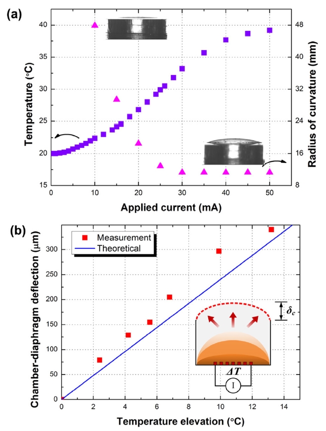
The thermopneumatic actuation of the air chamber was investigated first, because its performance is highly affected by the heat loss through the air chamber as well as by the Joule heating of the metallic heater. Measurements of the curvature were conducted using a drop-shape analyzer (DSA100, KRUSS). The fabricated lens was positioned in a pyrostat chamber maintained at 20℃ to exclude the influence of external temperature changes during the measurement. Figure 4(a) shows the temperature inside the air chamber and the
curvature of the chamber diaphragm as functions of the applied current. The temperature increases parabolically, obeying Joule’s law, until the current reaches 35 mA. At this saturation point, the temperature has increased by approximately 15℃ and the radius of curvature has reached 11.5 mm. However, once the input current exceeds 35 mA the rate of temperature elevation decreases gradually due to the restriction of Joule heating by the geometry of the heater and the strong dependence of electrical conductivity on temperature in metal. The temperature saturation of the air chamber results in almost no additional deformation of the diaphragm for an input current of greater than 35 mA. However, the maximum strain value of the PDMS diaphragm was reached at 30 mA, before the temperature saturation of the air chamber.
Figure 4(b) shows the deformation of the chamber diaphragm as a function of the temperature elevation that was measured to check the thermal insulation of the air chamber. The diaphragm deflection induced by the temperature elevation agrees with the theoretical prediction expressed by Eq. (1) in the region where the Joule’s law applies. This reveals that heat loss is minimized by the membrane structure between the silicon wafer and the metallic heater, as well as the low thermal conductivity of PDMS. Furthermore, the deflection of the air chamber diaphragm is reproducible even if accompanied by large curvature change. This reversible actuation in turn induces a consistent pressure load for deformation of the lens diaphragm. The minor discrepancy between the theoretical plot and the measured results is attributed to the differences between the actual parameters of PDMS and those assumed for numerical calculations.
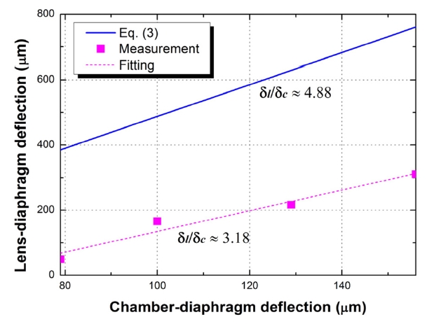
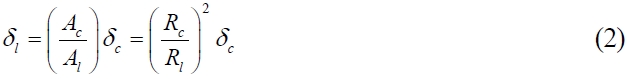
Figure 5 depicts the interrelationship between the deflection of the chamber diaphragm,
from the theoretical predictions are supposed to originate with two factors: the restoring force,
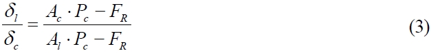
where
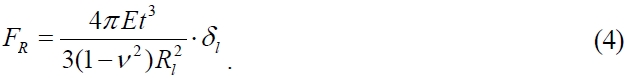
When the calculated
The measured rise time of the fabricated actuator was 30 s when the application current was 20 mA whereas fall time was 42 s. Due to passive cooling of the air chamber, fall time was longer than rise time.
3.2. Focusing Properties of the Fabricated Liquid Lens
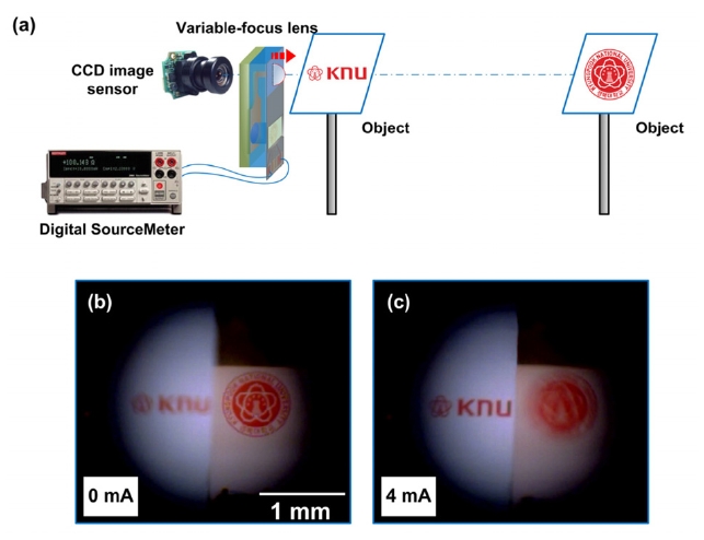
Figure 6(a) shows the experimental setup devised to observe the focusing performance of the fabricated thermopneumatic liquid lens. The aperture of the lens was 2 mm in diameter.Two objects were positioned at long and short distances, respectively, from the fabricated liquid lens mounted upon an image sensor system. Figure 6(b) shows the image observed with the unbiased condition that focused on the object positioned at the greater distance (long focal length). As shown in Fig. 6(c), with 4 mA of input current the lens diaphragm swelled up and then focused on the object positioned at the lesser distance (short focal length).
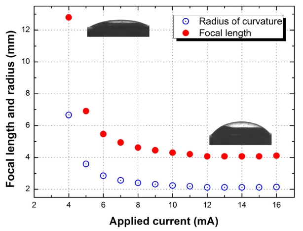
Figure 7 shows the radius of curvature of the lens diaphragm and the focal length determined from the curvature as functions of the applied current. As the input current increases, the focal length is reduced parabolically until it reaches 4 mm, where the radius of curvature is minimal (about 2 mm).
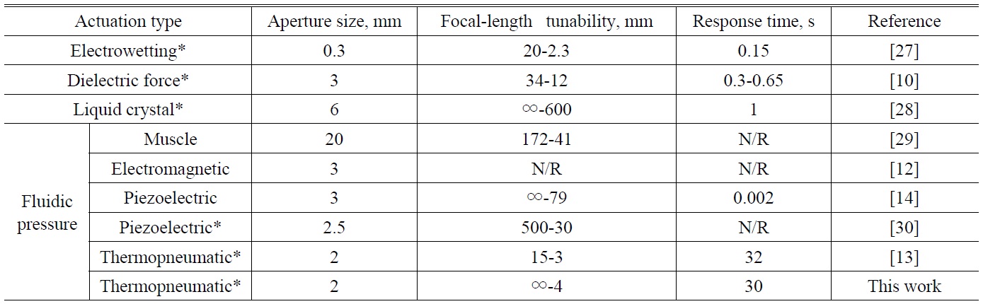
[TABLE 1.] Performance comparison of variable-focus lenses

Performance comparison of variable-focus lenses
Once the input current exceeds 12 mA, the focal length remains almost constant. This focal-length ceiling is due to the aforementioned pressure loss through the fluid channel. The thermal influence on the focal length tunability and temperature gradient at the lens aperture were not observed in this lens. The fluid channel linking between the thermopneu-matic actuator and lens cell, using low thermal conductive PDMS may separate the lens cell from a heat flux generated by the actuator. The power consumption to achieve a focal length of 4 mm was 144 mW, whereas the vertically integrated thermopneumatic lens was roughly 212 mW [13]. The time required to obtain a focal length of 4.6 mm when starting from infinity with 20 mA of input current was 30 s. Because the response time for shortening focal length of a thermopneumatic liquid lens is dominated by the heating time of the air in the chamber, different times can be realized by optimizing the volumetric design of the air chamber or the modulation of the current density. For applications that require a quicker response, the height of the air chamber can be reduced while maintaining a large area ratio between the chamber and lens diaphragms, as expressed by Eq. (2). In addition to any change in volumetric design, the input current density can also be properly modulated with time to achieve the desired focal length. This laterally integrated thermopneumatic lens showed approximately 6% faster heating speed than that of the vertically integrated lens at the same heating power of 300 mW [13]. Moreover, due to heat sink through the silicon at the air chamber, the lens had much faster response than the vertically integrated lens using the glass substrate [13]. Table 1 compares the performance of variable-focus lenses according to actuation type. Most previously reported liquid lenses driven by electrical signals, such as electrowetting, dielectric forces, and piezoelectricity, have quick responses. However, these do not possess a wide range of focal-length tunability. Although fluidic-pressure-based lenses possess sufficient lens aperture size to receive much optical information, they are difficult to miniaturize because of external actuators. The prototype of the proposed liquid lens combines novel focal-length tunability with sufficient aperture size (2 mm) and represents a significant advance towards a miniaturized high-performance liquid lens with an integrated actuator based on fluidic pressure. Furthermore, the thermopneumatic liquid lens is useful for an optical system that requires great focal-length tunability. A hybrid lens that incorporated the rapid and refined tunability of adaptive lenses and micro-solid lenses with the wide tunability of a thermopneumatic liquid lens might simultaneously achieve quick response, great focal-length tunability, and low chromatic aberration.
We designed and fabricated a novel variable-focus liquid lens with a vertically integrated thermopneumatic actuator. The focal-length tunability of the proposed lens was determined by the area ratio of the diaphragms positioned at the actuator and lens aperture. The integrated actuator induced a deflection of the lens diaphragm that was times greater than that of the air chamber diaphragm. The novel perfor-mance of the lens was obtained by careful thermal isolation of the integrated actuator. In practice the prototype lens achieved excellent focal-length tunability from infinity to 4 mm with a lens diameter of 2 mm. The proposed thermopneu-matic liquid lens combined with an adaptive lens might achieve both a wide focal range and quick response.