Integral imaging (II) is one of the attractive options among the various three-dimensional (3D) display techniques. II has advantages that it can provide continuous viewpoints and full-parallax compared to other commercial 3D display types such as parallax barrier, lenticular, and glass-types [1-4]. Similar to other 3D display systems, II also has difficulty in capturing 3D information from the real world [5, 6]. Therefore, computer generated II (CGII) has been used in many research fields [7-9].
II was first introduced by Lippmann in 1908 under the name of integral photography [10], but it did not receive wide attention at that time due to the lack of devices which can handle the 3D information sufficiently. With the great improvement of camera and display technology, digital image devices can capture, handle and display adequate 3D information for an II system [3, 4]. As the liquid crystal (LC) display, which is most widely used display type in recent years, has become able to offer a bright and high resolution two-dimensional (2D) image, II can also provide improved 3D images to the viewers with this device.
II is generally implemented by adding a lens array to 2D LC display (LCD). Therefore 3D image quality in II is decided by LCD specification. There is a tradeoff relation among resolution, viewing angle, and depth resolution, which are the basic 3D image quality factors in II, but their total physical quantity which directly indicates 3D image quality is limited by LCD resolution [11]. Therefore it is evidently reasonable to research how LCD characteristics influence 3D image quality in II. Kim et al. studied the Moire pattern of 3D images in II caused by subpixel structures of LCD [12], and Kim
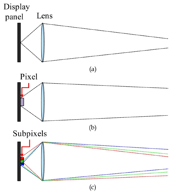
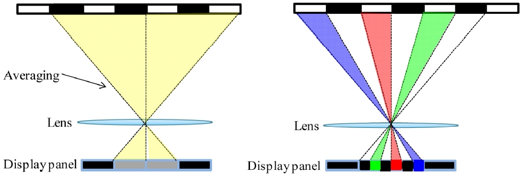
As shown in previous research, the microstructure of LCD usually causes some errors in II display. Figure 1 shows differences between the ideal case and practical case in II display. In the ideal case, the pixels in the display panel are infinitely small so that the rays diverge from a point as shown in Fig. 1(a). The rays that have passed through the lens converge at a point. The real world II display can be approximated to this ideal case when the lens is much bigger than a pixel [13].
But when the lens is small so that this approximation is invalid, the size of the pixel should be considered as in Fig. 1(b). The light rays are from the finite area of a pixel and the rays do not converge at a point anymore. Furthermore, when the subpixels of LCD are considered, the problem gets more complicated. The red, green, and blue rays are started at different positions, and they propagate separately as shown in Fig. 1(c). In general II display, when the lens gets smaller, the pixel gets bigger relatively, and the effect
from finite pixel size becomes severe. Therefore when the lens pitch is only several times bigger than a pixel, the errors caused by finite display pixel size become the major problem in II display [13].
Among the errors caused by finite display pixel size, we focused on two major errors. One is pickup and display mismatch error in CGII. In conventional CGII, the elemental image is generated without considering finite display pixel size. However in II display a pixel consists of three finite size subpixels and this mismatch causes 3D image quality decline and color separation problems. This error can be corrected by a subpixel pickup method. The other error on which we focus is mismatch error between pixel pitch and lens pitch. Because the lens pitch is usually not a multiple of the pixel pitch, lens border and pixel border are dislocated. This mismatch error causes image discontinuity and color separation problems. We can overcome this error with the modified elemental image generation method with consider-ation of positions of lenses and subpixels.
In this paper, we analyze two major errors caused by finite display pixel size in II and we propose the correction methods. In Section 2, we describe the major errors: pickup-and-display mismatch error in CGII and mismatch error between pixel pitch and lens pitch. Then we introduce the correction methods for each. In Section 3, we show how a subpixel pickup method corrects the first error. For the second error, a modified elemental image generation method is applied and we represent the details of this method in Section 4. Experimental results are presented in Section 5. Finally in Section 6, the conclusion and future applications are briefly discussed.
II. MAJOR ERRORS CAUSED BY FINITE DISPLAY PIXEL SIZE
2.1. Pickup & Display Mismatch Error in CGII
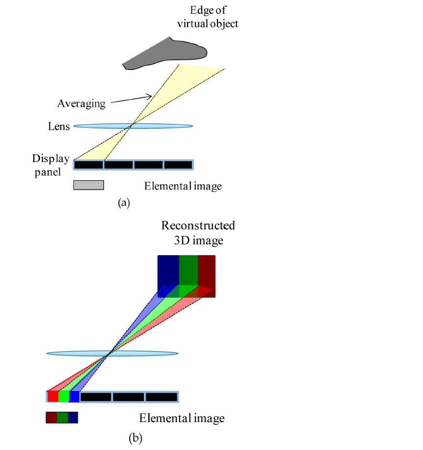
Pickup and display mismatch error is caused by wrong information extracted in the virtual pickup process in CGII. Figure 2(a) shows the capture of high resolution 3D information of a virtual object by conventional elemental image generation process in CGII. In conventional CGII, pickup process is performed in pixel scale, so the color infor-mation of the virtual object is averaged as shown in Fig. 2(a). However in the real world display process, the finite size three subpixels exist in a pixel and they display the averaged color information separately as shown in Fig. 2(b). With the elemental image obtained by the conventional method, the reconstructed 3D image cannot express the clear edge of the 3D image. This pickup-and-display mismatch causes 3D image quality decline.
2.2. Mismatch Error Between Pixel Pitch and Lens Pitch
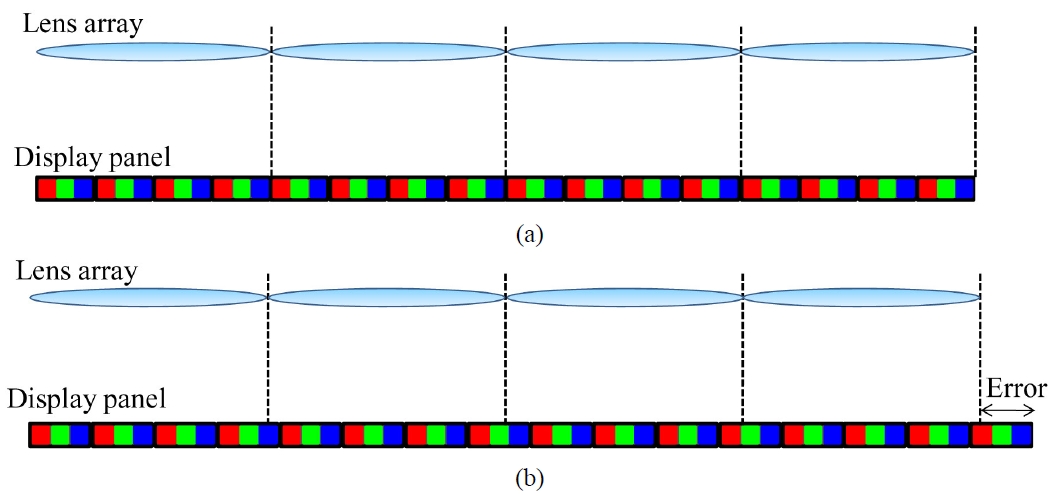
In conventional II, The lens pitch is assumed to be multiples of pixel pitch as shown in Fig. 3(a). However, when the lens pitch is not the multiples of pixel pitch,
lens border and pixel border are dislocated. And since a pixel has full-color information of a ray, the border pixel cannot provide correct information to the audience. If the lens is only a few times bigger than the pixel so that a lens covers only three or four pixels, then this mismatching error becomes severe as shown in Fig. 3(b). In this case if the elemental image is generated without consideration of this effect, then its information becomes totally meaningless after three or four lenses are passed. Unfortunately, the pixel pitch does not match with the lens pitch in many cases. Therefore, this pixel pitch and lens pitch mismatch error is also the major factor of image discontinuity and of color separation problems.
We propose a subpixel pickup method to correct the pickup and display mismatch error in CGII. Figure 4 briefly shows the conventional pickup process and the proposed subpixel pickup process in CGII. In conventional pickup method, a virtual camera captures red, green, and blue all at once in pixel scale. Hence the elemental image has averaged 3D information as shown in Fig. 4(a). As mentioned in Section 2.1, the reconstructed 3D image cannot express high lateral resolution with this method.
Therefore, we suggest a subpixel pickup method to solve this problem. In the subpixel pickup method, the virtual camera captures 3D information in subpixel scale. This method extracts red, green, and blue color information separately just as in the display process. Because it considers display subpixels, this proposed method can provide three times higher lateral resolution as shown in Fig. 4(b). Therefore, the elemental image generated by our proposed method contains more detailed 3D information than the elemental image generated by the conventional method, so that it can express the clear edge of the 3D image.
IV. MODIFIED SUBPIXEL PICKUP METHOD
To correct not only pickup and display mismatch error but the mismatch error between pixel pitch and lens pitch, we suggested a modified subpixel pickup method. Our proposed
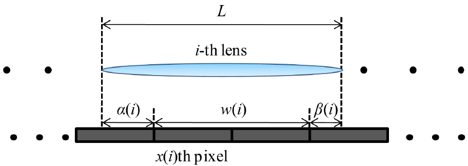
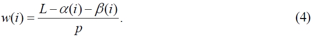
method is to generate the elemental image with the consider-ation of relative position of lenses and pixels. The proposed method is based on a subpixel pickup method. It extracts color information in subpixel scale. Furthermore, this method performs calculations for all of the subpixels and lenses to solve the dislocation problem. Figure 5 shows all position parameters used for the correction. We can calculate position parameters such as
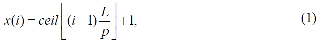


1) Assume that the 1st lens and the 1st pixel are calibrated and we calculate the position of the i-th lens.
2) Find the x(i): the first complete pixel inside i-th lens.
3) Find the remaining position parameters: α(i), β(i), and w(i).
4) Generate the elemental image only with the pixels completely inside the lens. 5) Generate the elemental image of border pixels with a weighted sum method.
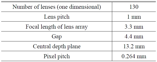
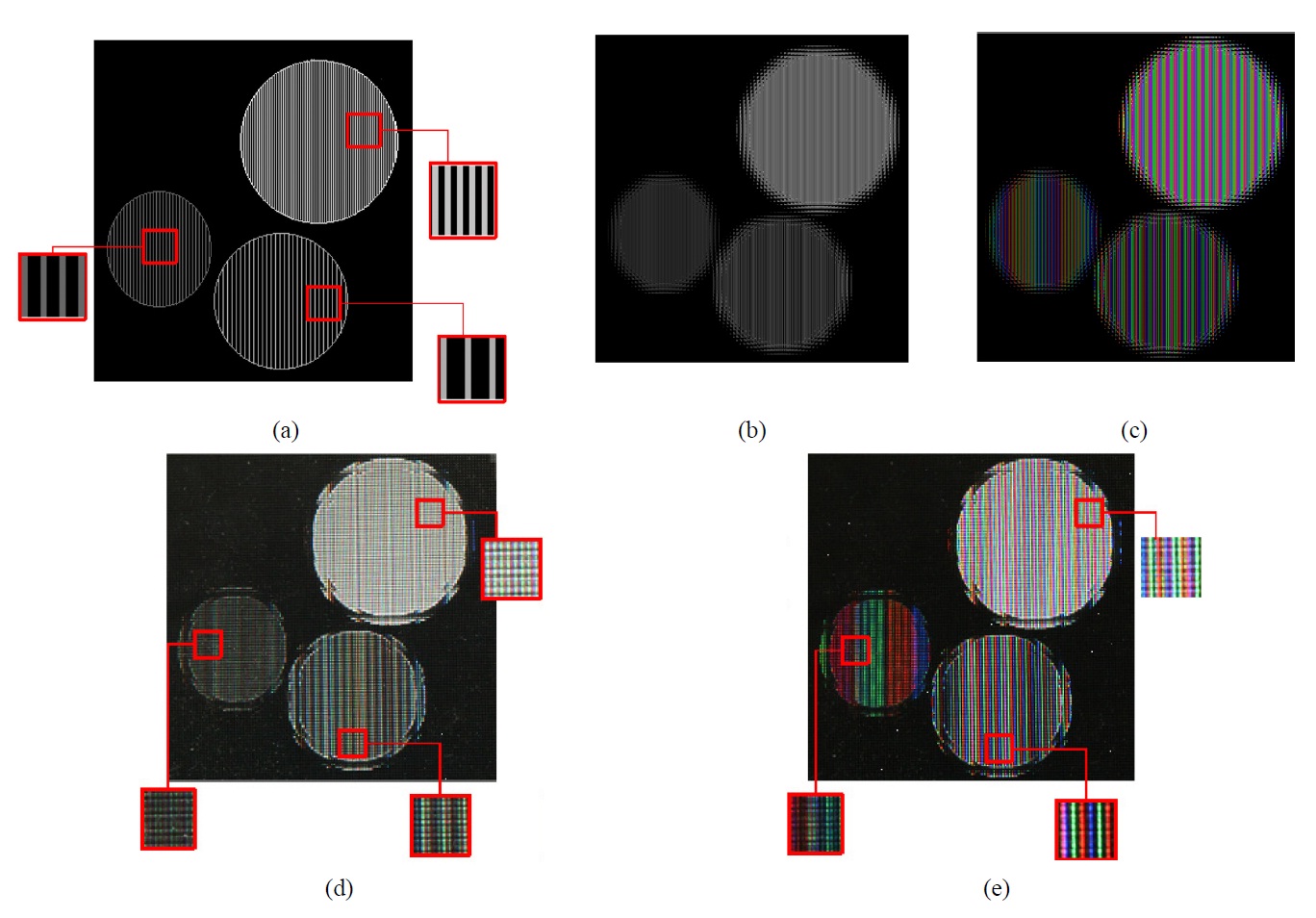
To show the validity of the subpixel pickup method, we performed experiments. Firstly, horizontally high resolution objects are used in experiments to test lateral resolution improvement. Table 1 shows the experimental conditions.We used an LCD panel with 0.264 mm pixel pitch and 1mm-size lens array whose focal length is 3.3 mm. The gap between panel and lens is 4.4 mm so that real mode II is performed. The lens pitch is approximately only 3.79 times bigger than the pixel pitch, so there is a proper condition to check the errors mentioned above. Figure 6(a) shows high resolution objects. As shown in Fig. 6(a), these objects have 1/2, 1/3, and 1/4 pixel-1 lateral frequency.With this experimental condition, lateral cutoff frequency of the conventional method is 1/3 pixel-1 and that of the proposed method is 1 pixel-1. Therefore we expect that some of the objects lose high frequency components with the conventional method, while the proposed method can provide high frequency information well.
Figures 6(b) and (c) show elemental images obtained by conventional and proposed methods. The conventional method cannot provide high frequency line patterns, while the proposed method can, as we expect. Figures 6(d) and (e) show experimental results. All of reconstructed objects with our proposed method express clear line patterns while only one of the objects provides line patterns with the conventional method. These results show clearly that the proposed method improves the ability to provide high lateral frequency. Although the proposed method expresses the wrong color information, it is not a significant problem with natural color objects because usually high frequency components exist only at edges and the proposed method can express sharp edges. Therefore this ability to express high frequency information has a
positive influence on reconstructed 3D image quality.
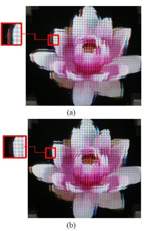
We also used a natural image for experiments as shown in Fig. 7. As shown in Figs. 8(a) and (b), the resulting image with the proposed method shows lateral resolution improvement and a clearer edge. However, both of them still show image discontinuity and color separation problems due to another error caused by finite display pixel size. Without the consideration of a subpixel’s exact position, the subpixel pickup method is not that meaningful as the results show.
[TABLE 1.] Experimental conditions

Experimental conditions
This result shows that another correction algorithm should be added to the subpixel pickup method.
5.2. Modified Subpixel Pickup Method
Further experiments are performed to test our proposed
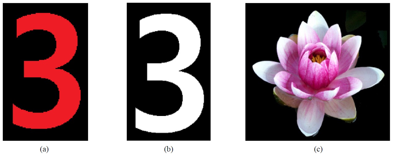
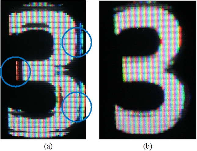
modified subpixel pickup method. We expect that resultant images with the proposed method would be quality improved compared with the subpixel pickup method. Figure 9 shows object images. Firstly, a monochromatic image is used to reveal the image discontinuity problem, and then a white color image is used to test the color separation problem. Finally we test a natural image. Experiments are performed under the same conditions listed in Table 1.
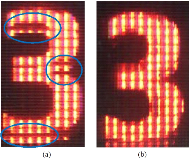
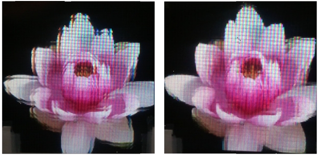
Figure 10 shows the resultant image with a monochromatic object. In Fig. 10(a), with the conventional method, image the discontinuity problem is shown. But with the proposed method, this error decreased remarkably as shown in Fig 10(b). With the white color object shown in Fig. 11, the color separation problem was also solved by using the proposed method. These results show that major problems with the subpixel pickup method are solved with the proposed modified subpixel pickup method as we expected. Figure 12 shows clear improvement on image quality with the
natural image. The modified subpixel pickup method corrects the errors caused by finite display pixel size.
We proposed a subpixel scale elemental image generation method to correct the errors created by finite pixel size in II. In this paper, two errors are mainly discussed: pickup and display mismatch error and mismatch error between pixel pitch and lens pitch. Our proposed pickup method considers the relative positions between lenses and pixels in subpixel scale. This method calculates the position para-meters,generates elemental image with pixels completely inside the lens, and generates elemental image with border pixels using weighted sum method. Appropriate experiments are presented to verify the validity of the proposed method, and the experimental results show that the proposed method solves the errors caused by finite pixel size. Further study is expected to apply this methodology to other similar 3D display systems such as lenticular and parallax barrier using LCD.