Next-generation LED lighting is more advantageous than existing fluorescent and incandescent lighting in terms of long life expectancy, high tolerance to humidity, low power consumption, and minimal heat generation [1]. In addition, LEDs are used not only for illumination but also for many products such as monitors, cell phones, cars, and others. Recently, there have been many attempts to converge LED with IT technology [2,3]. Among them, Visible Light Communication (VLC), which is the convergence of illumination and communication, has emerged [4-6]. A corresponding VLC standardization was recently published by the IEEE Standards Association [7,8]. Generally, VLC uses the Intensity Modulation with a Direct Detection (IM/DD) scheme, which uses the amplitude (or intensity) of light to transmit data. Human eyes perceive only the average intensity when light changes faster than the Maximum Flickering Time Period (MFTP), which is defined as 5 ms [8]. Therefore, both lighting and communication can be simultaneously implemented. By considering both terms together, many modulation methods have been proposed, such as inverted pulse position modulation (I-PPM), subcarrier inverted pulse position modulation (SC-I-PPM) [9], pulse width modulation (PWM) [10], and variable PPM (VPPM) [8]. Among them, VPPM is the modulation scheme proposed by the IEEE 802.15 standard group. To support illumination with dimming control and communication simultaneously, it uses binary PPM for communication and PWM for dimming control. However, the main drawback of the VPPM scheme is that the data rate is limited to the bandwidth of an LED since it uses only binary PPM modulation.
In this paper, we propose a new VLC modulation scheme called multi-coded variable pulse position modulation (MCVPPM). Two groups of signals (PWM and PPM group) are multi-coded by orthogonal codes for transmitting data simultaneously. Then, each multi-level value of the multicoded signal is converted to pulse width and position, which results in not only an improved data rate, but improved processing gain in reception as well. In addition, we introduce average duty ratio and cyclic shift concepts in PWM. To this effect, it is possible to support dimming control for light illumination without any degradation in communication performance. Through simulations, we compare BER and the achievable data rate of MC-VPPM and conventional VPPM schemes in a visible light optical channel environment. When comparing BER to VPPM, much greater achievable data rate is shown in BER. The rest of the paper is organized as follows. Section II describes the proposed MC-VPPM scheme. Simulation results and conclusions are given in Sections III and IV, respectively.
II. MULTI-CODED VARIABLE PPM SCHEME
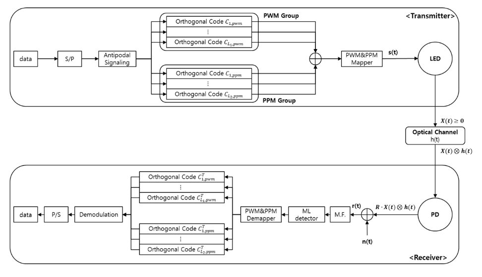
Fig. 1 shows the block diagram of the proposed multi-coded VPPM scheme for VLC. As shown in the Figure, the transmitting data block is divided into two separate parts. b
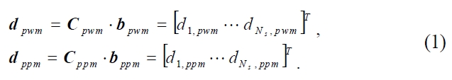
where
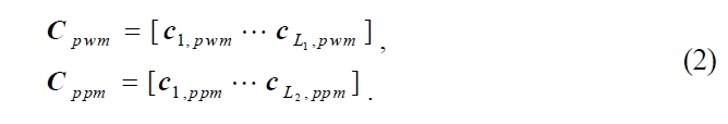
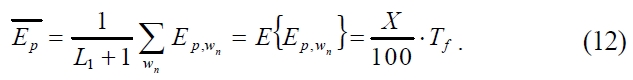
code matrices.
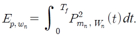
In this paper, we propose a new concept called average duty ratio of pulse


To transmit the signal, each element of a multi-coded signal vector for PWM is converted to a pulse width vector as shown below:

where
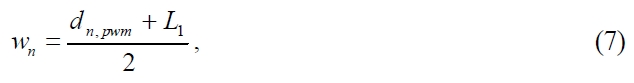
and the corresponding pulse width
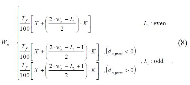
Here,
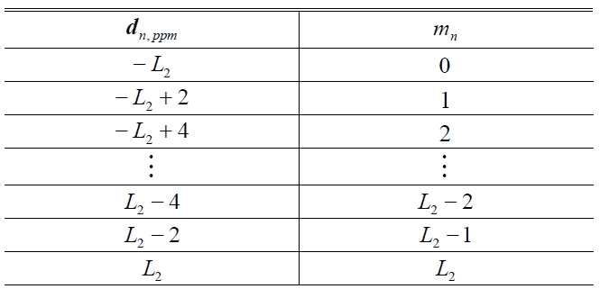
In the case of PPM, each element of a multi-coded signal vector for PPM is converted to a pulse position vector as follows:

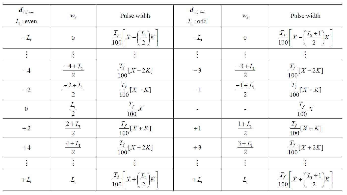
PWM mapping rule
PPM mapping rule
where
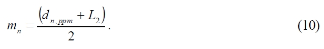
Table 2 shows the PPM mapping rule according to eq. (10).
Based on the pulse width and pulse position vector, the transmitted multi-coded VPPM signal has the form
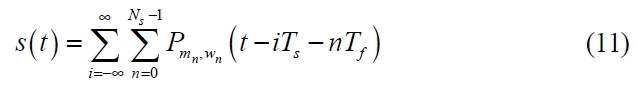
where
The transmitted signal that contains

satisfies the following constraint:
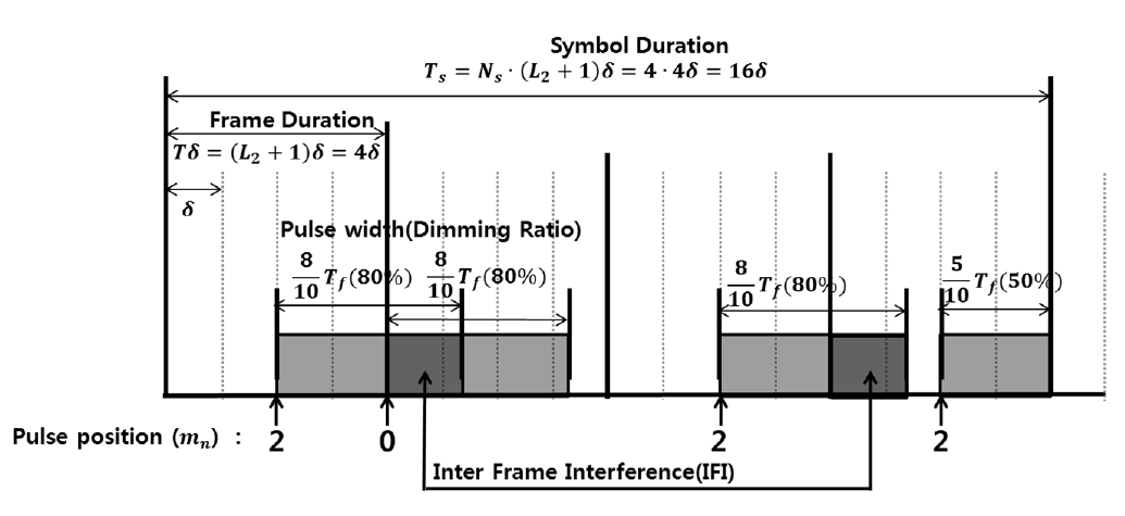
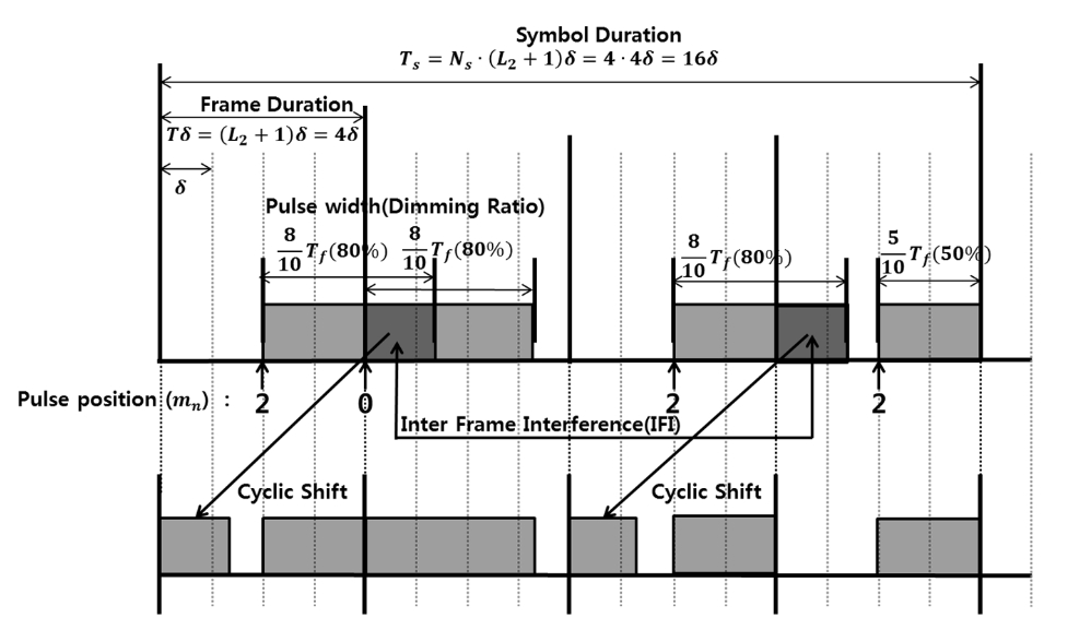
The signaling example of the proposed multi-coded VPPM is shown in Fig. 2.
In order to produce the corresponding signals b
From the Figure, we can see that there are pulses that exceed their own frame durations (
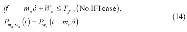
where
The graphical representation of the Cyclic Shift scheme by using the example given in Fig. 2 is shown as below:
Finally, an LED is driven by the current signal controlled by the MC-VPPM signal
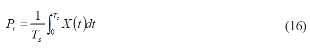
After passing through the VLC optical channel
Here,
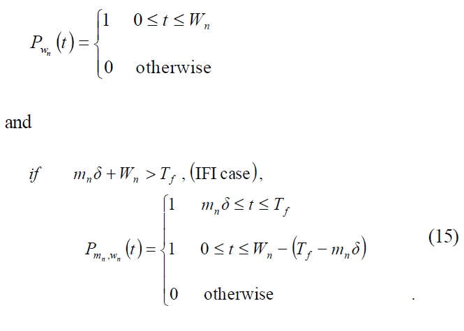
The average received optical power becomes
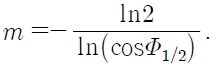
represents the channel DC gain. If we consider a LOS case with no reflections, the channel DC gain is:
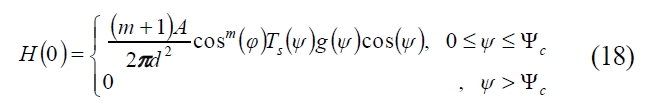
where
For example,
We assume that the Gaussian noise
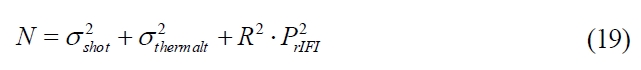
If the duration of the signal is long enough, the ISI is negligible. Therefore, the main noise sources become shot and thermal noises. A shot noise variance is given by [4]
where
where the first two terms represent feedback-resistor noise and RET channel noise, respectively.
Here, we assume that the detector responsibility is ideal (
where
Here,
Based on the maximum-likelihood (ML) decision rule, we detect the position and pulse width
of the transmitted pulses and regenerate the multi-coded signal vector as shown below:

where

Then, the two multi-coded signal vectors received,


are given as follows:
where
Finally,

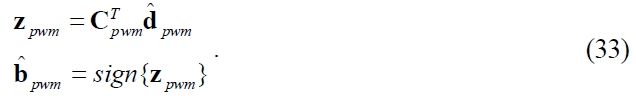
are decoded by orthogonal codes used at the transmitter with hard decision as follows:
Until now, we have discussed the overall description of the proposed MC-VPPM scheme. Now, we present the simulated result to validate the proposed scheme. The initial system parameters of MC-VPPM for simulation are shown in Table 3.
We used the VLC channel environment [12] and parameters for determining noise variances in [4] and [12]. For performance comparison, we include the conventional VPPM scheme [8], which is coded with an orthogonal code of length 4 to obtain the same processing gain as the proposed MC-VPPM scheme. Note that we are focusing on evaluating the BER performance of the proposed MC-VPPM modulation scheme. Therefore, we consider an uncoded system.
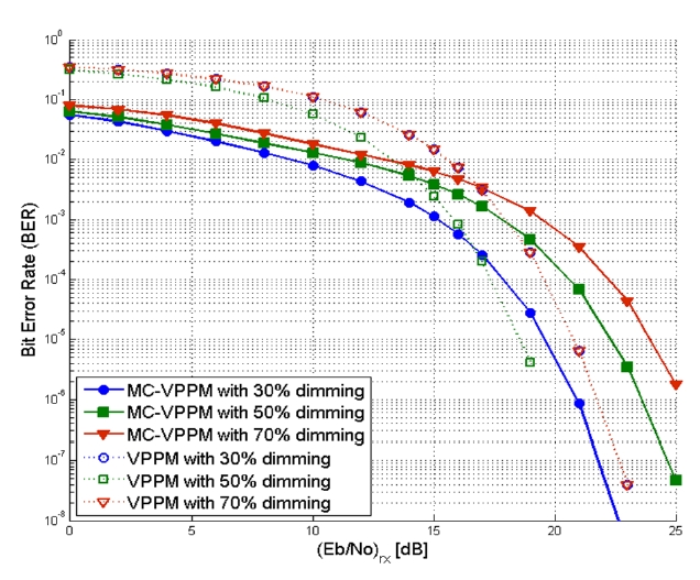
Fig. 4 shows the comparison of BERs for the proposed MC-VPPM and VPPM scheme according to the received
[TABLE 3.] The initial system parameters of MC-VPPM
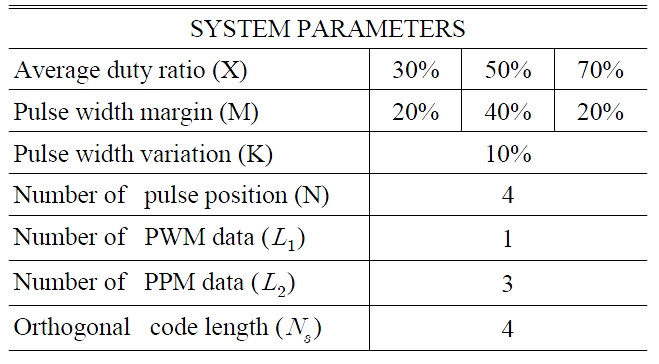
The initial system parameters of MC-VPPM
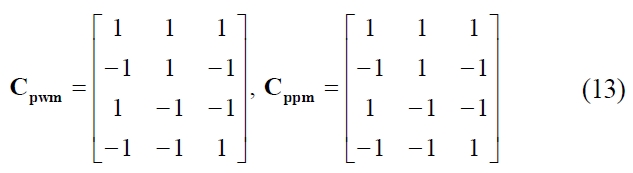
cation performance based on distance and dimming ratio under the given VLC scenario.
From the above result, it is observed that MC-VPPM shows better BER performance as the dimming level decreases. This is because the interference caused by increased dimming levels in determining correlation metrics results in performance degradation, even though more energy is allocated to the transmitted signal thanks to higher dimming level increases in (
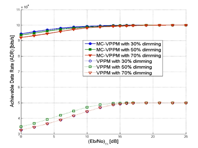
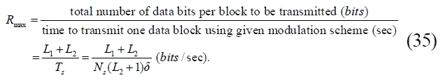
As mentioned before, we compared the achievable data rate (ADR) between the proposed MC-VPPM and VPPM schemes. ADR represents how much data can be transmitted without error per unit time. Therefore, ADR can be expressed as a function of the maximum data rate and the bit error rate (BER):

where
Finally, we can obtain the achievable data rate (ADR) of the proposed MC-VPPM given as
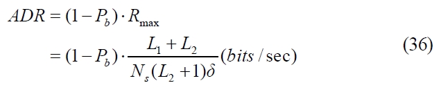
Fig. 6 shows the comparison of achievable data rate between two schemes when the optical rate of the LED is 400kHz. As expected, the achievable data rate of MCVPPM is much greater than that of the VPPM scheme.
We have proposed a new VLC scheme based on multi-coded variable PPM (MC-VPPM) for VLC. By converting multi-level values of the multi-coded signals to pulse positions and pulse width, the proposed MC-VPPM gives both improved data rate and robust BER. For light illumination, dimming can be also supported without any degradation in communication performance by introducing average duty ratio and cyclic shift concepts in to the PWM. Through simulations based on VLC scenarios, we confirmed the robust BER curves and much-greater achievable data rates of the proposed MC-VPPM in comparison with conventional VPPM schemes.


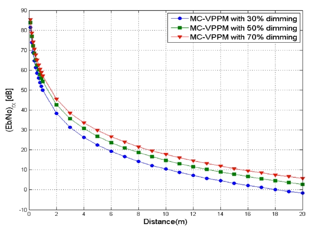
![The (Eb/N0)rx performance of MC-VPPM according to the dimming ratio under the VLC scenario in [12] and the distance between the LED and PD. ( LED power is 2 uW, optical rate : 400 kHz )](http://oak.go.kr/repository/journal/11477/E1OSAB_2012_v16n2_107_f005.jpg)